EP0965568B1 - Machine pour le moulage d'objets en verre - Google Patents
Machine pour le moulage d'objets en verre Download PDFInfo
- Publication number
- EP0965568B1 EP0965568B1 EP19990111408 EP99111408A EP0965568B1 EP 0965568 B1 EP0965568 B1 EP 0965568B1 EP 19990111408 EP19990111408 EP 19990111408 EP 99111408 A EP99111408 A EP 99111408A EP 0965568 B1 EP0965568 B1 EP 0965568B1
- Authority
- EP
- European Patent Office
- Prior art keywords
- push
- button
- printed circuit
- machine
- cover plate
- Prior art date
- Legal status (The legal status is an assumption and is not a legal conclusion. Google has not performed a legal analysis and makes no representation as to the accuracy of the status listed.)
- Expired - Lifetime
Links
- 238000000465 moulding Methods 0.000 title claims description 14
- 239000011521 glass Substances 0.000 claims description 9
- 125000006850 spacer group Chemical group 0.000 claims description 5
- 229920000459 Nitrile rubber Polymers 0.000 claims description 3
- 150000002825 nitriles Chemical class 0.000 claims description 3
- 229920002379 silicone rubber Polymers 0.000 claims description 3
- 239000004945 silicone rubber Substances 0.000 claims description 3
- 238000007789 sealing Methods 0.000 claims 14
- 230000001681 protective effect Effects 0.000 description 6
- 238000004140 cleaning Methods 0.000 description 5
- 238000005520 cutting process Methods 0.000 description 4
- 239000003599 detergent Substances 0.000 description 4
- 239000007788 liquid Substances 0.000 description 3
- 239000000463 material Substances 0.000 description 3
- 238000000137 annealing Methods 0.000 description 2
- 230000000712 assembly Effects 0.000 description 2
- 238000000429 assembly Methods 0.000 description 2
- 239000011324 bead Substances 0.000 description 2
- 239000000356 contaminant Substances 0.000 description 2
- 238000001125 extrusion Methods 0.000 description 2
- 238000004519 manufacturing process Methods 0.000 description 2
- 239000011159 matrix material Substances 0.000 description 2
- 229920002799 BoPET Polymers 0.000 description 1
- OKTJSMMVPCPJKN-UHFFFAOYSA-N Carbon Chemical compound [C] OKTJSMMVPCPJKN-UHFFFAOYSA-N 0.000 description 1
- 239000005041 Mylar™ Substances 0.000 description 1
- 229910052799 carbon Inorganic materials 0.000 description 1
- 239000003795 chemical substances by application Substances 0.000 description 1
- 238000010276 construction Methods 0.000 description 1
- 238000005238 degreasing Methods 0.000 description 1
- 238000010586 diagram Methods 0.000 description 1
- 239000000428 dust Substances 0.000 description 1
- 230000003670 easy-to-clean Effects 0.000 description 1
- 239000011810 insulating material Substances 0.000 description 1
- 239000002184 metal Substances 0.000 description 1
- 239000006060 molten glass Substances 0.000 description 1
- 238000005192 partition Methods 0.000 description 1
- 229920003023 plastic Polymers 0.000 description 1
- 230000000284 resting effect Effects 0.000 description 1
- 230000001360 synchronised effect Effects 0.000 description 1
Images

Classifications
-
- H—ELECTRICITY
- H01—ELECTRIC ELEMENTS
- H01H—ELECTRIC SWITCHES; RELAYS; SELECTORS; EMERGENCY PROTECTIVE DEVICES
- H01H13/00—Switches having rectilinearly-movable operating part or parts adapted for pushing or pulling in one direction only, e.g. push-button switch
- H01H13/70—Switches having rectilinearly-movable operating part or parts adapted for pushing or pulling in one direction only, e.g. push-button switch having a plurality of operating members associated with different sets of contacts, e.g. keyboard
- H01H13/7006—Switches having rectilinearly-movable operating part or parts adapted for pushing or pulling in one direction only, e.g. push-button switch having a plurality of operating members associated with different sets of contacts, e.g. keyboard comprising a separate movable contact element for each switch site, all other elements being integrated in layers
-
- C—CHEMISTRY; METALLURGY
- C03—GLASS; MINERAL OR SLAG WOOL
- C03B—MANUFACTURE, SHAPING, OR SUPPLEMENTARY PROCESSES
- C03B9/00—Blowing glass; Production of hollow glass articles
- C03B9/30—Details of blowing glass; Use of materials for the moulds
- C03B9/40—Gearing or controlling mechanisms specially adapted for glass-blowing machines
- C03B9/41—Electric or electronic systems
-
- H—ELECTRICITY
- H01—ELECTRIC ELEMENTS
- H01H—ELECTRIC SWITCHES; RELAYS; SELECTORS; EMERGENCY PROTECTIVE DEVICES
- H01H2219/00—Legends
- H01H2219/002—Legends replaceable; adaptable
-
- H—ELECTRICITY
- H01—ELECTRIC ELEMENTS
- H01H—ELECTRIC SWITCHES; RELAYS; SELECTORS; EMERGENCY PROTECTIVE DEVICES
- H01H2223/00—Casings
- H01H2223/002—Casings sealed
-
- H—ELECTRICITY
- H01—ELECTRIC ELEMENTS
- H01H—ELECTRIC SWITCHES; RELAYS; SELECTORS; EMERGENCY PROTECTIVE DEVICES
- H01H2229/00—Manufacturing
- H01H2229/062—Maintenance or repair facilities
-
- H—ELECTRICITY
- H01—ELECTRIC ELEMENTS
- H01H—ELECTRIC SWITCHES; RELAYS; SELECTORS; EMERGENCY PROTECTIVE DEVICES
- H01H2239/00—Miscellaneous
- H01H2239/01—Miscellaneous combined with other elements on the same substrate
- H01H2239/014—Miscellaneous combined with other elements on the same substrate on both sides
Definitions
- the present invention relates to a machine for molding glassware.
- Glassware is known to be molded on so-called I.S. molding machines, which comprise a supply assembly for supplying a succession of glass gobs; and a number of molding sections, each comprising a respective group of molds, and each for receiving respective glass gobs from the supply assembly and successively forming respective glass articles.
- the supply assembly comprises an extrusion assembly for forming a bead of molten glass; a scissor cutting assembly for cutting the bead transversely into successive glass gobs; a gob distributor for receiving the gobs from the cutting assembly; and, for each group of molds, a respective gob delivery assembly for receiving the glass gobs from the distributor and feeding the gobs to the respective molds.
- the articles are extracted from the molds by respective actuator assemblies, which transfer the articles from the respective molds to a common conveyor by which the articles are fed to an annealing furnace.
- the extrusion assembly, cutting assembly, gob distributor and actuating assemblies are controlled and synchronized by an electronic control unit comprising a central control unit and, for each section, a respective machine-operator push-button panel located close to the respective group of molds.
- Each push-button panel normally comprises a respective frame, and a number of separate push-buttons with respective casings connected to the frame and partially housing respective movable-contact actuating elements projecting from the respective casings.
- the push-buttons are protected by a common shield normally made of deformable, transparent plastic material and connected in fluidtight manner to the frame.
- Push-button panel of the kind disclosed above is disclosed in US 5.340.955
- the protective shields are poorly tolerated by machine operators, who are normally forced to work wearing special gloves, which in themselves hinder operation of the push-buttons, and who see the protective shields as yet a further hindrance.
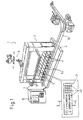
- Number 1 in Figure 1 indicates as a whole a machine for producing glassware and comprising a base 2, a gantry-type frame 3 extending from base 2, and a number of molding sections 4 (shown schematically) for molding respective glass articles (not shown). More specifically, each section 4 comprises a respective known group of molds 5 (not described in detail) for forming, in succession, a number of glass articles from respective glass gobs (not shown) supplied by a supply assembly 6; and a respective manipulating device 5a for removing the articles from the respective group of molds and feeding the articles onto a conveyor 5b by which the articles are fed to an annealing furnace (not shown).
- machine 1 is controlled by a respective electronic control unit 7 comprising a known electronic central control unit 8 and, for each section 4, a respective sealed push-button panel 9 which, in the particular example described, is supported by frame 3 over and adjacent to base 2, and by which machine 1 is operator-controlled manually to disable and/or make changes to the production cycles performed by the machine under the control of electronic central control unit 8.
- a respective electronic control unit 7 comprising a known electronic central control unit 8 and, for each section 4, a respective sealed push-button panel 9 which, in the particular example described, is supported by frame 3 over and adjacent to base 2, and by which machine 1 is operator-controlled manually to disable and/or make changes to the production cycles performed by the machine under the control of electronic central control unit 8.
- each push-button panel 9 comprises a printed-circuit board 10; a front cover plate 11 and a rear closing plate 12 parallel to each other and to board 10 and located on opposite sides of board 10; and an intermediate plate 13 extending between board 10 and cover plate 11.
- Board 10 and rear plate 12 are separated by a spacer element 15 which, together with board 10 and rear plate 12, defines a cavity 16 (shown partly in Figure 2) housing a number of known components 17, such as diodes, resistors, etc., soldered directly onto the surface 18 of board 10 and facing plate 12.
- a spacer element 15 which, together with board 10 and rear plate 12, defines a cavity 16 (shown partly in Figure 2) housing a number of known components 17, such as diodes, resistors, etc., soldered directly onto the surface 18 of board 10 and facing plate 12.
- cover plate 11 is defined externally by a flat surface 19, and comprises a number of through openings 20, each of which extends at a respective through opening 21 in intermediate plate 13 and defines, together with respective opening 21, a seat for housing a respective known push-button 22.
- each push-button 22 comprises a fixed annular guide body 26 engaging opening 21; and two movable bodies 23 and 24 connected, preferably glued, integrally with each other.
- Body 24 is connected in sliding manner to annular guide body 26 and acts, in use, on a known dome-shaped switch 25 of the printed circuit; and body 23 engages opening 20 and is fitted with an outer plate 27 identifying the respective push-button 22, and the outer surface 28 of which is substantially coplanar with surface 19 of plate 11.
- each push-button panel 9 also comprises a sheet 29 of insulating material, preferably a material known as "Mylar", interposed between intermediate plate 13 and board 10; and two seals 30 and 31 preferably made of nitrile or silicone rubber.
- Seal 30 extends between plates 11 and 13 and is gripped between bodies 23 and 24; and seal 31 extends between closing plate 12 and spacer element 15. Plates 11, 12, 13, seals 30, 31 and spacer element 15 are gripped together by a number of screws 33 - only one of which is shown in Figure 2 - to define a sealed chamber 34 for housing board 10, relative components 17 and a number of metal actuators 25.
- Chamber 34 also houses a number of light sources 35 resting on the opposite surface of board 10 to surface 18 and each soldered directly onto board 10 at the inlet of a conduit 36 extending through plates 11 and 13 and crossed by a transparent partition 37 preferably defined by an intermediate portion of seal 30.
- each push-button 22 is replaced by a push-button 38, which differs from push-buttons 22 by comprising a movable body 39, which is formed in one piece, extends through openings 20 and 21, and is connected to annular guide body 26 in an angularly fixed position and so as to slide to and from board 10.
- Body 39 comprises an outer circumferential groove 41 housing a respective annular portion 42 of seal 30, and comprises an end portion 43 extending through opening 20 and fitted releasably - preferably by means of a bayonet joint 44 - with a disk-shaped body 45 loosely engaging opening 20 and fitted integrally with respective identification plate 27 which, together with respective body 45, forms part of push-button 38.
- dome-shaped switches 25 of the printed circuit are each replaced by a known miniaturized sealed switch 46 (not described in detail) also soldered to board 10.
- the push-buttons defining push-button panels 9 are connected to central control unit 8 in such a way as to define a controllable switching matrix 47. That is, by programming matrix 47, each function enabled/disabled by the push-button panel may be associated with any one of push-buttons 22 of push-button panels 9 so that the position of push-button 22 on the push-button panel is not related to the function enabled/disabled by operating the push-button.
- push-button panels 9 as described are therefore highly resistant not only to dust and contaminants in the vicinity of machine 1, but also to any type of liquid detergent used to clean the machine.
- Printed-circuit board 10, components 17 on board 10, switches 25 and light sources 35 are housed inside a fully sealed chamber and therefore permanently isolated from the outside, so that machine 1 can be cleaned by hydrocleaners using any type of liquid detergent, and push-button panels 9 treated, i.e. subjected to thorough cleaning, in the same way as groups of molds 5 or frame 3.
- cleaning is further simplified by push-buttons 22, unlike known push-buttons, no longer projecting but forming part of a perfectly flat, and therefore easy-to-clean, outer surface.
- push-button panels 9 no longer require additional protective shields, which not only makes cleaning easier but also simplifies operation of the push-buttons, even by machine operators wearing protective gloves.
- push-button panels 9 described, and in particular the presence of plates 11, 12 and 27, make the push-button panels practically shockproof and unaffected by any means used to operate them. Tests have shown push-button panels 9 as described to be highly heat-resistant and therefore locatable, with substantially no problems, in environments formerly avoided by being particularly hostile, also in terms of temperature.
- any push-button to any panel-controlled function provides for "customizing" the push-button panels, i.e. enabling different users to perform each function using push-buttons located in positions selectable according to specific requirements. Customizing the push-button panels is also further simplified by identification plates 27 being interchangeable easily and relatively quickly, especially by virtue of bayonet joints 44.
- push-buttons 22 may be formed differently from those described by way of example; different solutions may be adopted for sealed chamber 34 housing board 10, components 17, switches 25, 46 and light sources 35; light sources 35 may even be dispensed with or located differently from those shown by way of example; and insulating sheet 29 may be made of material other than that indicated and/or may be replaced by or associated with a further seal to define, together with seal 31, a further sealed chamber inside sealed chamber 34.
Landscapes
- Engineering & Computer Science (AREA)
- Chemical & Material Sciences (AREA)
- Mechanical Engineering (AREA)
- Manufacturing & Machinery (AREA)
- Materials Engineering (AREA)
- Organic Chemistry (AREA)
- Push-Button Switches (AREA)
- Glass Compositions (AREA)
Claims (14)
- Machine (1) pour mouler de la verrerie, la machine comprenant plusieurs sections de moulage (4), pour mouler chacune successivement plusieurs articles en verre; et des moyens de commande (7) pour commander lesdites sections (4) et comprenant pour chaque section (4), au moins un panneau à boutons-poussoirs (9) comprenant plusieurs boutons-poussoirs (22; 38), une plaque de couverture extérieure (11) entourant lesdits boutons-poussoirs (22, 38); un circuit imprimé (10) supportant plusieurs composants (17); des moyens de commutation (25; 46) associés audit circuit imprimé (10) pour chaque bouton-poussoir (22; 38); une plaque de fermeture extérieure (12) disposée sur le côté opposé dudit circuit imprimé (10) par rapport à ladite plaque de couverture extérieure (11), et des premiers moyens d'obturation (30) disposés entre la plaque de couverture (11) et le circuit imprimé (10) et éloignés du circuit imprimé (10) ; caractérisée en ce qu'elle comprend en outre des seconds moyens d'obturation (31) disposés sur le côté opposé dudit circuit imprimé (10), desdits composants (17) et desdits moyens de commutation (25; 46) par rapport aux premiers moyens d'obturation (30) et faisant face à ladite plaque de fermeture extérieure (12) pour former ensemble avec lesdits premiers moyens d'obturation (30) une chambre fermée (34) pour loger ledit circuit imprimé (10), les composants (17) relatifs à ce circuit et lesdits moyens de commutation (25 ; 46); lesdits seconds moyens d'obturation comprenant une couche (31) de nitrile ou de caoutchouc de silicone et étant éloignés dudit circuit imprimé par un élément d'espacement (15) pour définir ladite chambre fermée.
- Machine telle que revendiquée dans la revendication 1, caractérisée en ce que chaque bouton-poussoir (22) comprend une partie d'extrémité extérieure (23) au moins partiellement entourée par ladite plaque de couverture extérieure (11) et définie par une surface extérieure (28) sensiblement coplanaire avec une surface extérieure (19) de ladite plaque de couverture (11).
- Machine telle que revendiquée dans la revendication 2, caractérisée en ce qu'elle comprend également des moyens d'espacement (15) interposés entre ledit circuit imprimé (10) et ladite plaque de fermeture extérieure (12) ; lesdits seconds moyens d'obturation (31) étant interposés entre lesdits moyens d'espacement (15) et ladite plaque de fermeture extérieure (12).
- Machine telle que revendiquée dans la revendication 3, caractérisée en ce que ledit panneau à boutons-poussoirs (9) comprend en outre des moyens de serrage libérables pour serrer ensemble ladite plaque de couverture extérieure (11), ladite plaque de fermeture extérieure (12), lesdits moyens d'espacement (15) et lesdits premiers et seconds moyens d'obturation (30 (31).
- Machine telle que revendiquée dans l'une quelconque des revendications précédentes, caractérisée en ce que chaque bouton-poussoir (38) comprend un corps d'activation unique (39) agissant sur lesdits moyens de commutation (25; 46) relatifs; une plaque extérieure (27) identifiant le bouton-poussoir (38); et des moyens de connexion (44, 45) libérables interposés entre ledit corps d'activation (39) et ladite plaque extérieure (27).
- Machine telle que revendiquée dans la revendication 5, caractérisée en ce que lesdits moyens de connexion (44, 45) comprennent un joint en baïonnette (44).
- Machine telle que revendiquée dans l'une quelconque des revendications précédentes, caractérisée en ce que lesdits moyens de commande (7) comprennent également une unité de commande électronique (8); et des moyens de commutation contrôlables (47) interposés entre lesdits panneaux à boutons-poussoirs (9) et ladite unité de commande électronique (8) pour assigner à chaque bouton-poussoir (22; 38) une quelconque des fonctions activé/désactivé par lesdits panneaux à boutons-poussoirs (9).
- Panneau à boutons-poussoirs (9), particulièrement pour une machine (1) pour mouler de la verrerie, comprenant plusieurs boutons-poussoirs (22; 38), une plaque de couverture extérieure (11) entourant lesdits boutons-poussoirs (22, 38); un circuit imprimé (10) supportant plusieurs composants (17); des moyens de commutation (25; 46) associé audit circuit imprimé (10) pour chaque bouton-poussoir (22; 38); une plaque de fermeture extérieure (12) disposée sur le côté opposé dudit circuit imprimé (10) par rapport à ladite plaque de couverture extérieure (11), et des premiers moyens d'obturation (30) disposés entre la plaque de couverture (11) et le circuit imprimé (10) et éloignés du circuit imprimé (10); caractérisé en ce qu'il comprend en outre des seconds moyens d'obturation (31) disposés sur le côté opposé dudit circuit imprimé (10), desdits composants (17) et desdits moyens de commutation (25; 46) par rapport aux premiers moyens d'obturation (30) et faisant face à ladite plaque de fermeture extérieure (12) pour former ensemble avec lesdits premiers moyens d'obturation (30) une chambre fermée (34) pour loger ledit circuit imprimé (10), les composants (17) relatifs à ce circuit et lesdits moyens de commutation (25; 46); lesdits seconds moyens d'obturation comprenant une couche (31) de nitrile ou de caoutchouc de silicone et étant éloignés dudit circuit imprimé par un élément d'espacement (15) pour définir ladite chambre fermée.
- Panneau à boutons-poussoirs tel que revendiqué dans la revendication 8, caractérisé en ce que chaque bouton-poussoir (22) comprend une partie d'extrémité extérieure (23) au moins partiellement entourée par ladite plaque de couverture extérieure (11) et définie par une surface extérieure (28) sensiblement coplanaire avec une surface extérieure (19) de ladite plaque de couverture (11).
- Panneau à boutons-poussoirs tel que revendiqué dans la revendication 8 ou 9, caractérisé en ce qu'il comporte également des moyens d'espacement (15) interposés entre ledit circuit imprimé (10) et ladite plaque de fermeture extérieure (12) ; lesdits seconds moyens d'obturation (31) étant interposés entre lesdits moyens d'espacement (15) et ladite plaque de fermeture extérieure (12).
- Panneau à boutons-poussoirs tel que revendiqué dans la revendication 10, caractérisé en ce qu'il comporte en outre des moyens de serrage libérables (33) pour serrer ensemble ladite plaque de couverture extérieure (11), ladite plaque de fermeture extérieure (12), lesdits moyens d'espacement (15) et lesdits premiers et seconds moyens d'obturation (30 (31).
- Panneau à boutons-poussoirs tel que revendiqué dans la revendication 11, caractérisé en ce que lesdits moyens de serrage libérables comprennent au moins un ensemble vis boulon-vis.
- Panneau à boutons-poussoirs tel que revendiqué dans l'une quelconque des revendications 8 à 12, caractérisé en ce que chaque bouton-poussoir (38) comprend un corps d'activation unique (39) agissant sur lesdits moyens de commutation (25; 46) relatifs; une plaque extérieure (27) identifiant le bouton-poussoir (38); et des moyens de connexion libérables (44, 45) interposés entre ledit corps d'activation (39) et ladite plaque extérieure (27).
- Panneau à boutons-poussoirs tel que revendiqué dans la revendication 13, caractérisé en ce que lesdits moyens de connexion (44, 45) comprennent un joint en baïonnette.
Applications Claiming Priority (2)
| Application Number | Priority Date | Filing Date | Title |
|---|---|---|---|
| ITTO980533 | 1998-06-19 | ||
| IT98TO000533A ITTO980533A1 (it) | 1998-06-19 | 1998-06-19 | Macchina per la formatura di articoli di vetro. |
Publications (3)
| Publication Number | Publication Date |
|---|---|
| EP0965568A2 EP0965568A2 (fr) | 1999-12-22 |
| EP0965568A3 EP0965568A3 (fr) | 2000-05-10 |
| EP0965568B1 true EP0965568B1 (fr) | 2004-10-06 |
Family
ID=11416860
Family Applications (1)
| Application Number | Title | Priority Date | Filing Date |
|---|---|---|---|
| EP19990111408 Expired - Lifetime EP0965568B1 (fr) | 1998-06-19 | 1999-06-11 | Machine pour le moulage d'objets en verre |
Country Status (4)
| Country | Link |
|---|---|
| EP (1) | EP0965568B1 (fr) |
| DE (1) | DE69920806T2 (fr) |
| ES (1) | ES2229583T3 (fr) |
| IT (1) | ITTO980533A1 (fr) |
Families Citing this family (2)
| Publication number | Priority date | Publication date | Assignee | Title |
|---|---|---|---|---|
| DE10145769A1 (de) * | 2001-09-17 | 2003-04-24 | Siemens Ag | Tastatur für Kommunikationsendgeräte |
| EP2441393B1 (fr) * | 2010-10-14 | 2013-03-06 | Eberle GmbH & Co. KG | Instrument chirurgical |
Family Cites Families (10)
| Publication number | Priority date | Publication date | Assignee | Title |
|---|---|---|---|---|
| US3762907A (en) * | 1971-02-22 | 1973-10-02 | Ball Corp | Glass forming machine having an automatic control system |
| US3905793A (en) * | 1974-10-21 | 1975-09-16 | Emhart Corp | Computer control for glassware forming machine |
| US3969600A (en) * | 1975-06-11 | 1976-07-13 | Burroughs Corporation | Tactile feedback keyboard switch assembly and actuator |
| US4529429A (en) * | 1983-05-06 | 1985-07-16 | Ball Corporation | Digital glass forming machine |
| US4771139A (en) * | 1986-06-27 | 1988-09-13 | Desmet Gregory L | Keyboard with metal cover and improved switches |
| US5345389A (en) * | 1992-04-21 | 1994-09-06 | Vhc, Ltd. | Electronic controller for a glassware forming machine |
| US5340955A (en) * | 1992-07-20 | 1994-08-23 | Digitran Company, A Division Of Xcel Corp. | Illuminated and moisture-sealed switch panel assembly |
| US5475192A (en) * | 1993-03-15 | 1995-12-12 | Teikoku Tsushin Kogyo Co., Ltd. | Keytop sheet for push-button switches |
| US5399821A (en) * | 1993-10-20 | 1995-03-21 | Teikoku Tsushin Kogyo Co., Ltd. | Keytop for push-button switches, and method of manufacturing same |
| US5721666A (en) * | 1995-02-28 | 1998-02-24 | Master Molded Products Corporation | Device panel with in-molded applique |
-
1998
- 1998-06-19 IT IT98TO000533A patent/ITTO980533A1/it unknown
-
1999
- 1999-06-11 EP EP19990111408 patent/EP0965568B1/fr not_active Expired - Lifetime
- 1999-06-11 DE DE69920806T patent/DE69920806T2/de not_active Expired - Lifetime
- 1999-06-11 ES ES99111408T patent/ES2229583T3/es not_active Expired - Lifetime
Also Published As
| Publication number | Publication date |
|---|---|
| EP0965568A3 (fr) | 2000-05-10 |
| DE69920806D1 (de) | 2004-11-11 |
| DE69920806T2 (de) | 2006-02-23 |
| ITTO980533A1 (it) | 1999-12-19 |
| ES2229583T3 (es) | 2005-04-16 |
| EP0965568A2 (fr) | 1999-12-22 |
Similar Documents
| Publication | Publication Date | Title |
|---|---|---|
| US4225766A (en) | Touch contact | |
| KR100745879B1 (ko) | 유도 가열 조리기 | |
| GB2211928A (en) | Control system for an electric cooker | |
| EP1030536A3 (fr) | Commutateur de proximité destiné à un appareil électro-ménager | |
| EP0965568B1 (fr) | Machine pour le moulage d'objets en verre | |
| WO2019112123A1 (fr) | Purificateur d'eau | |
| ES2276497T5 (es) | Campo de cocción con control de tiempo integrado | |
| ATE484066T1 (de) | Elektronik-bedieneinheit | |
| US20030160669A1 (en) | Magnetic and mechanical switches | |
| WO2019235750A1 (fr) | Appareil de cuisson | |
| EP0847067A3 (fr) | Bouton pourssoir en forme de feuille | |
| ES2357040T3 (es) | Encimera de cocción con dispositivo de mando. | |
| KR920007746B1 (ko) | 푸시 버튼 스위치 어셈블리 | |
| WO2021029608A1 (fr) | Mélangeur | |
| EP1233653A3 (fr) | Panneau de commande tactile destiné à sélectionner des zones de cuisson | |
| JPS57151414A (en) | Controlling device for airconditioner of vehicle | |
| JP2004079530A (ja) | 多機能押しボタンスイッチ | |
| JPH03133016A (ja) | 押しボタンスイッチを備えた操作器 | |
| WO2020075974A1 (fr) | Ensemble panneau et appareil ménager le comprenant | |
| KR19990029086A (ko) | 조작장치와, 이것을 사용한 가열조리기구 및 그 조작방법 | |
| US8025742B2 (en) | Dishwasher with controller device | |
| JP5405256B2 (ja) | 加熱調理器 | |
| GB2089575A (en) | Clocks | |
| JPH04230919A (ja) | 押しボタンスイッチ | |
| KR930005348B1 (ko) | 누름버튼이 일체로 성형된 리모콘 조작기의 케이싱 |
Legal Events
| Date | Code | Title | Description |
|---|---|---|---|
| PUAI | Public reference made under article 153(3) epc to a published international application that has entered the european phase |
Free format text: ORIGINAL CODE: 0009012 |
|
| AK | Designated contracting states |
Kind code of ref document: A2 Designated state(s): DE ES FR GB SE |
|
| AX | Request for extension of the european patent |
Free format text: AL;LT;LV;MK;RO;SI |
|
| PUAL | Search report despatched |
Free format text: ORIGINAL CODE: 0009013 |
|
| AK | Designated contracting states |
Kind code of ref document: A3 Designated state(s): AT BE CH CY DE DK ES FI FR GB GR IE IT LI LU MC NL PT SE |
|
| AX | Request for extension of the european patent |
Free format text: AL;LT;LV;MK;RO;SI |
|
| RIC1 | Information provided on ipc code assigned before grant |
Free format text: 7C 03B 9/16 A, 7C 03B 9/41 B, 7G 06F 3/00 B, 7H 01H 13/70 B, 7H 01H 13/06 B, 7B 29C 33/00 B, 7B 29C 45/14 B |
|
| 17P | Request for examination filed |
Effective date: 20000803 |
|
| AKX | Designation fees paid |
Free format text: DE ES FR GB SE |
|
| 17Q | First examination report despatched |
Effective date: 20020829 |
|
| GRAP | Despatch of communication of intention to grant a patent |
Free format text: ORIGINAL CODE: EPIDOSNIGR1 |
|
| GRAS | Grant fee paid |
Free format text: ORIGINAL CODE: EPIDOSNIGR3 |
|
| GRAA | (expected) grant |
Free format text: ORIGINAL CODE: 0009210 |
|
| AK | Designated contracting states |
Kind code of ref document: B1 Designated state(s): DE ES FR GB SE |
|
| REG | Reference to a national code |
Ref country code: GB Ref legal event code: FG4D |
|
| REF | Corresponds to: |
Ref document number: 69920806 Country of ref document: DE Date of ref document: 20041111 Kind code of ref document: P |
|
| REG | Reference to a national code |
Ref country code: SE Ref legal event code: TRGR |
|
| REG | Reference to a national code |
Ref country code: ES Ref legal event code: FG2A Ref document number: 2229583 Country of ref document: ES Kind code of ref document: T3 |
|
| ET | Fr: translation filed | ||
| PLBE | No opposition filed within time limit |
Free format text: ORIGINAL CODE: 0009261 |
|
| STAA | Information on the status of an ep patent application or granted ep patent |
Free format text: STATUS: NO OPPOSITION FILED WITHIN TIME LIMIT |
|
| 26N | No opposition filed |
Effective date: 20050707 |
|
| PGFP | Annual fee paid to national office [announced via postgrant information from national office to epo] |
Ref country code: GB Payment date: 20120525 Year of fee payment: 14 Ref country code: FR Payment date: 20120705 Year of fee payment: 14 |
|
| PGFP | Annual fee paid to national office [announced via postgrant information from national office to epo] |
Ref country code: ES Payment date: 20120614 Year of fee payment: 14 |
|
| GBPC | Gb: european patent ceased through non-payment of renewal fee |
Effective date: 20130611 |
|
| REG | Reference to a national code |
Ref country code: FR Ref legal event code: ST Effective date: 20140228 |
|
| PG25 | Lapsed in a contracting state [announced via postgrant information from national office to epo] |
Ref country code: GB Free format text: LAPSE BECAUSE OF NON-PAYMENT OF DUE FEES Effective date: 20130611 |
|
| PG25 | Lapsed in a contracting state [announced via postgrant information from national office to epo] |
Ref country code: FR Free format text: LAPSE BECAUSE OF NON-PAYMENT OF DUE FEES Effective date: 20130701 |
|
| REG | Reference to a national code |
Ref country code: ES Ref legal event code: FD2A Effective date: 20150710 |
|
| PG25 | Lapsed in a contracting state [announced via postgrant information from national office to epo] |
Ref country code: ES Free format text: LAPSE BECAUSE OF NON-PAYMENT OF DUE FEES Effective date: 20130612 |
|
| PGFP | Annual fee paid to national office [announced via postgrant information from national office to epo] |
Ref country code: DE Payment date: 20150521 Year of fee payment: 17 Ref country code: SE Payment date: 20150526 Year of fee payment: 17 |
|
| REG | Reference to a national code |
Ref country code: DE Ref legal event code: R119 Ref document number: 69920806 Country of ref document: DE |
|
| REG | Reference to a national code |
Ref country code: SE Ref legal event code: EUG |
|
| PG25 | Lapsed in a contracting state [announced via postgrant information from national office to epo] |
Ref country code: SE Free format text: LAPSE BECAUSE OF NON-PAYMENT OF DUE FEES Effective date: 20160612 |
|
| PG25 | Lapsed in a contracting state [announced via postgrant information from national office to epo] |
Ref country code: DE Free format text: LAPSE BECAUSE OF NON-PAYMENT OF DUE FEES Effective date: 20170103 |