EP0965746A1 - Verfahren zur Fehlererkennung einer Einlassluftheizvorrichtung einer Fahrzeugbrennkraftmaschine, und Einlassluftheizvorrichtung und Überwachungsvorrichtung zur Verwendung in einer Fahrzeugbrennkraftmaschine - Google Patents
Verfahren zur Fehlererkennung einer Einlassluftheizvorrichtung einer Fahrzeugbrennkraftmaschine, und Einlassluftheizvorrichtung und Überwachungsvorrichtung zur Verwendung in einer Fahrzeugbrennkraftmaschine Download PDFInfo
- Publication number
- EP0965746A1 EP0965746A1 EP99117406A EP99117406A EP0965746A1 EP 0965746 A1 EP0965746 A1 EP 0965746A1 EP 99117406 A EP99117406 A EP 99117406A EP 99117406 A EP99117406 A EP 99117406A EP 0965746 A1 EP0965746 A1 EP 0965746A1
- Authority
- EP
- European Patent Office
- Prior art keywords
- temperature
- engine
- predetermined
- controller
- flag
- Prior art date
- Legal status (The legal status is an assumption and is not a legal conclusion. Google has not performed a legal analysis and makes no representation as to the accuracy of the status listed.)
- Granted
Links
- 238000010438 heat treatment Methods 0.000 title claims abstract description 83
- 238000002485 combustion reaction Methods 0.000 title claims abstract description 18
- 238000000034 method Methods 0.000 title claims description 23
- 230000003213 activating effect Effects 0.000 claims abstract description 20
- 238000010009 beating Methods 0.000 claims 1
- 239000003570 air Substances 0.000 description 143
- 238000002405 diagnostic procedure Methods 0.000 description 9
- 230000004044 response Effects 0.000 description 9
- 238000012360 testing method Methods 0.000 description 7
- 230000001276 controlling effect Effects 0.000 description 6
- 239000000779 smoke Substances 0.000 description 6
- 230000006870 function Effects 0.000 description 4
- 238000004519 manufacturing process Methods 0.000 description 3
- 238000001514 detection method Methods 0.000 description 2
- 238000012774 diagnostic algorithm Methods 0.000 description 2
- 230000000694 effects Effects 0.000 description 2
- 238000005286 illumination Methods 0.000 description 2
- 238000012986 modification Methods 0.000 description 2
- 230000004048 modification Effects 0.000 description 2
- 230000003287 optical effect Effects 0.000 description 2
- 230000000717 retained effect Effects 0.000 description 2
- 239000007858 starting material Substances 0.000 description 2
- 230000000153 supplemental effect Effects 0.000 description 2
- 244000304337 Cuminum cyminum Species 0.000 description 1
- 230000002411 adverse Effects 0.000 description 1
- 230000004075 alteration Effects 0.000 description 1
- 239000012080 ambient air Substances 0.000 description 1
- 230000003750 conditioning effect Effects 0.000 description 1
- 230000001351 cycling effect Effects 0.000 description 1
- 229930195733 hydrocarbon Natural products 0.000 description 1
- 150000002430 hydrocarbons Chemical class 0.000 description 1
- 239000002085 irritant Substances 0.000 description 1
- 231100000021 irritant Toxicity 0.000 description 1
- 238000012544 monitoring process Methods 0.000 description 1
- 238000012545 processing Methods 0.000 description 1
- 230000001737 promoting effect Effects 0.000 description 1
- 230000009467 reduction Effects 0.000 description 1
- 230000001105 regulatory effect Effects 0.000 description 1
- 230000000241 respiratory effect Effects 0.000 description 1
- 230000011664 signaling Effects 0.000 description 1
- 230000036413 temperature sense Effects 0.000 description 1
- 238000012546 transfer Methods 0.000 description 1
- 238000012795 verification Methods 0.000 description 1
- 238000010792 warming Methods 0.000 description 1
Images


Classifications
-
- F—MECHANICAL ENGINEERING; LIGHTING; HEATING; WEAPONS; BLASTING
- F02—COMBUSTION ENGINES; HOT-GAS OR COMBUSTION-PRODUCT ENGINE PLANTS
- F02N—STARTING OF COMBUSTION ENGINES; STARTING AIDS FOR SUCH ENGINES, NOT OTHERWISE PROVIDED FOR
- F02N19/00—Starting aids for combustion engines, not otherwise provided for
- F02N19/02—Aiding engine start by thermal means, e.g. using lighted wicks
- F02N19/04—Aiding engine start by thermal means, e.g. using lighted wicks by heating of fluids used in engines
- F02N19/06—Aiding engine start by thermal means, e.g. using lighted wicks by heating of fluids used in engines by heating of combustion-air by flame generating means, e.g. flame glow-plugs
-
- F—MECHANICAL ENGINEERING; LIGHTING; HEATING; WEAPONS; BLASTING
- F02—COMBUSTION ENGINES; HOT-GAS OR COMBUSTION-PRODUCT ENGINE PLANTS
- F02M—SUPPLYING COMBUSTION ENGINES IN GENERAL WITH COMBUSTIBLE MIXTURES OR CONSTITUENTS THEREOF
- F02M31/00—Apparatus for thermally treating combustion-air, fuel, or fuel-air mixture
- F02M31/02—Apparatus for thermally treating combustion-air, fuel, or fuel-air mixture for heating
- F02M31/04—Apparatus for thermally treating combustion-air, fuel, or fuel-air mixture for heating combustion-air or fuel-air mixture
- F02M31/042—Combustion air
-
- F—MECHANICAL ENGINEERING; LIGHTING; HEATING; WEAPONS; BLASTING
- F02—COMBUSTION ENGINES; HOT-GAS OR COMBUSTION-PRODUCT ENGINE PLANTS
- F02M—SUPPLYING COMBUSTION ENGINES IN GENERAL WITH COMBUSTIBLE MIXTURES OR CONSTITUENTS THEREOF
- F02M31/00—Apparatus for thermally treating combustion-air, fuel, or fuel-air mixture
- F02M31/02—Apparatus for thermally treating combustion-air, fuel, or fuel-air mixture for heating
- F02M31/12—Apparatus for thermally treating combustion-air, fuel, or fuel-air mixture for heating electrically
- F02M31/13—Combustion air
-
- F—MECHANICAL ENGINEERING; LIGHTING; HEATING; WEAPONS; BLASTING
- F02—COMBUSTION ENGINES; HOT-GAS OR COMBUSTION-PRODUCT ENGINE PLANTS
- F02N—STARTING OF COMBUSTION ENGINES; STARTING AIDS FOR SUCH ENGINES, NOT OTHERWISE PROVIDED FOR
- F02N19/00—Starting aids for combustion engines, not otherwise provided for
- F02N19/02—Aiding engine start by thermal means, e.g. using lighted wicks
- F02N19/04—Aiding engine start by thermal means, e.g. using lighted wicks by heating of fluids used in engines
-
- Y—GENERAL TAGGING OF NEW TECHNOLOGICAL DEVELOPMENTS; GENERAL TAGGING OF CROSS-SECTIONAL TECHNOLOGIES SPANNING OVER SEVERAL SECTIONS OF THE IPC; TECHNICAL SUBJECTS COVERED BY FORMER USPC CROSS-REFERENCE ART COLLECTIONS [XRACs] AND DIGESTS
- Y02—TECHNOLOGIES OR APPLICATIONS FOR MITIGATION OR ADAPTATION AGAINST CLIMATE CHANGE
- Y02T—CLIMATE CHANGE MITIGATION TECHNOLOGIES RELATED TO TRANSPORTATION
- Y02T10/00—Road transport of goods or passengers
- Y02T10/10—Internal combustion engine [ICE] based vehicles
- Y02T10/12—Improving ICE efficiencies
Definitions
- This invention relates in general to internal combustion engines and more specifically to air intake heating and diagnostic systems for diesel engines which aid in cold weather starting and control white smoke exhaust emissions upon starting the engine and as required thereafter during operation of the engine.
- white smoke An undesirable phenomenon known as "white smoke” is a frequent side effect of no load or light load diesel engine operation at low temperatures. This phenomenon is essentially the result of unburned hydrocarbons in the engine exhaust and is attributable to misfiring or incomplete combustion in some or all cylinders. White smoke is both a respiratory and optical irritant as well as adversely affecting visibility. While white smoke is not a regulated exhaust emission, sociability of the engine or vehicle suffers as a result of the production of white smoke.
- Trotta et al. discloses a method and apparatus for preheating intake manifold air prior to starting the engine, and for postheating the intake air while the engine is running. In so doing, a pair of intake manifold air heaters are each activated for predetermined durations, and at predetermined duty cycles, according to specific ranges of intake air temperature.
- CARB California Air Resources Board
- OBD II On Board Diagnostics
- the present invention provides a system and method for heating intake manifold air to reduce white smoke while providing continuous diagnostic testing of the various system componentry.
- a system complies with OBD II by continuously warning a driver, under certain conditions more fully described hereinafter, of an existing fault or failure condition within the intake manifold air heating system.
- a diagnostic system for warning a vehicle operator of a fault in an air intake heating system for supplying heated air to an internal combustion engine of the vehicle.
- the air intake heating system has means for sensing intake manifold air temperature and producing a temperature signal corresponding thereto, the engine has switch means for starting and stopping the engine, the switch means being switchable between "off", “on” and “crank” states, and the system further has means for prompting the operator to wait for a predetermined time period prior to starting the engine after switching the switch means from its "off” state to its "on” state.
- the diagnostic system comprises means for storing first and second predetermined reference temperature signals, first and second predetermined time periods, and means for warning the vehicle operator of an air intake heating system fault, and controller means for detecting air intake heating system faults and activating the warning means and the prompting means in response thereto.
- the controller means receives the temperature signal and (a) continuously activates and deactivates the prompting means at a predetermined frequency in response to the temperature signal falling below the first reference temperature signal for at least the first predetermined time period, and (b) activates the warning means in response to the temperature signal exceeding the second reference temperature signal for at least the second predetermined time period, when the switch means is switched from its "off" state to its "on” state prior to starting the engine, until the switch means is returned to its "off” state.
- a method of warning a vehicle operator of a fault in an air intake heating system for supplying heated air to an internal combustion engine of the vehicle is provided.
- the air intake heating system has means for sensing intake manifold air temperature
- the engine has switch means for starting and stopping the engine, and the switch means is switchable between "off", "on” and “crank” states.
- the method comprises the steps of: (1) switching the switch means from its "off” state to its "on” state, (2) sensing intake manifold air temperature, (3) comparing the sensed intake manifold air temperature to a first and second predetermined reference temperature, (4) warning the vehicle operator of one of (a) a first fault condition if the sensed intake manifold air temperature falls below the first predetermined reference temperature for at least a first predetermined time period, and (b) a second fault condition if the sensed intake air temperature exceeds the second predetermined reference temperature for at least a second predetermined time period, and (5) continuously performing steps (2)-(4) from prior to starting the engine until the switch means is switched to its "off” state to thereby stop the engine.
- a diagnostic system for detecting faults in an air intake heating system for supplying heated air to an internal combustion engine of a vehicle has means for sensing intake manifold air temperature and producing a temperature signal corresponding thereto, means for sensing engine speed level and producing an engine speed signal corresponding thereto and means for heating the intake manifold air, the engine has switch means for starting and stopping the engine, the switch means being switchable between “off", “on” and “crank” states, where the means for sensing intake manifold air temperature senses an initial air temperature when the switch means is switched from its "off” state to its “on” state prior to starting the engine.
- the diagnostic system comprises means for storing a number of predetermined temperature threshold levels, a predetermined time period arid a number of flags, and controller means for detecting air intake heating system faults.
- the controller means receives the temperature and engine speed signals and continuously computes the difference between the intake manifold air temperature and the initial temperature for a predetermined postheat time period, and stores a first flag within the storing means if the difference exceeds a particular one of the number of predetermined temperature threshold levels within the predetermined time period, and stores a second flag within the storing means if the difference has not exceeded the particular one of the number of predetermined temperature threshold levels within the predetermined time period, if the initial temperature is below a first predetermined temperature level and the engine speed is above a first predetermined RPM level, and otherwise storing the first flag within the storing means.
- a method of detecting faults in an air intake heating system for supplying heated air to an internal combustion engine of a vehicle has means for sensing intake manifold air temperature, means for sensing engine speed, means for heating the intake manifold air and a memory, the engine has switch means for starting and stopping the engine, and the switch means is switchable between "off", "on” and "crank” states.
- the method comprises the steps of: (1) switching the switch means from its “off” state to its “on” prior to starting the engine, (2) sensing an initial intake manifold air temperature when the switch means is switched from its “off” state to its “on” state, (3) sensing engine speed after starting the engine, (4) performing steps (5)-(7) if the initial intake manifold air temperature is below a predetermined temperature level and the engine speed is above a predetermined RPM level, and otherwise storing a first flag within the memory, (5) determining the difference between the intake manifold air temperature and the initial intake manifold air temperature, (6) storing the first flag within the memory if the difference exceeds a predetermined temperature threshold level within a first predetermined time period, (7) storing a second flag within the memory if the difference does not exceed the predetermined temperature threshold level within the first predetermined time period, and (8) performing steps (5)-(7) for a second predetermined time period unless one of the first and second flags is stored within the memory.
- an air intake heating and diagnostic system for use with a vehicle having an internal combustion engine.
- the system comprises means for sensing intake manifold air temperature and producing a temperature signal corresponding thereto, means for starting and stopping the engine, the starting and stopping means being switchable between "off", “on” and “crank” states and producing an ignition signal corresponding to each of the states, the manifold air intake temperature sensing means sensing an initial intake manifold air temperature when the ignition signal is switched from its "off” state to its “on” state, means for warning the operator of the vehicle of a fault condition detected in the system, means for heating intake manifold air, and means for controlling the air intake heating means for a variable preheat time period prior to starting the engine.
- the controller means has a first input for receiving the temperature signal and a second input for receiving the ignition signal.
- the controller means receives the temperature and ignition signals, and responds to a first fault condition by replacing the variable preheat time period with a predetermined preheat time period and activating the warning means and the intake manifold air heating means, if the temperature signal falls below a first predetermined temperature level for at least a first predetermined time period, and responds to a second fault condition by activating the warning means, deactivating the intake manifold air heating means and expiring the variable preheat time period, if the temperature signal exceeds a second predetermined temperature level for at least a second predetermined time period.
- the controller means activates the intake manifold air heating means for the variable preheat time period in accordance with predetermined ranges of the initial temperature if neither of the first and second fault conditions are detected within the variable preheat time period and the initial temperature is below a first predetermined temperature level.
- a method of controlling an air intake heating system for an internal combustion engine of a vehicle for a variable preheat time period prior to starting the engine has means for sensing intake manifold air temperature, means for heating intake manifold air, means for warning an operator of the vehicle of a fault detected in the system and means for prompting the operator to wait for the variable preheat time period prior to starting the engine, the engine has switch means for starting and stopping the engine, and the switch means is switchable between "off", "on” and "crank” states.
- the method comprises the steps of (1) switching the switch means from its “off” state to its “on” state prior to starting the engine and sensing an initial intake manifold air temperature when the switch means is switched from its "off” state to its “on” state, (2) performing steps (3)-(13) for the variable preheat time period in accordance with the initial intake manifold air temperature, if the initial intake manifold air temperature is below a first predetermined temperature level, (3) activating the prompting means, (4) sensing the intake manifold air temperature and comparing the intake manifold air temperature to first and second reference temperatures,(5) performing steps (6)-(8) if the intake manifold air temperature falls below the first predetermined reference temperature for a first predetermined time period, (6) setting the variable preheat time period to a predetermined preheat time period, (7) activating the intake manifold air heating means, (8) continuously activating and deactivating the prompting means at a predetermined frequency; (9) performing steps (10)-(12) if the intake manifold air temperature exceeds the second pre
- an air intake heating and diagnostic system for use with a vehicle having an internal combustion engine.
- the system comprises means for sensing intake manifold air temperature and producing a temperature signal corresponding thereto, means for sensing engine speed and producing an engine speed signal corresponding thereto, means for starting and stopping the engine, the starting and stopping means being switchable between "off", “on” and “crank” states and producing an ignition signal corresponding to each of the states, the means for sensing manifold air temperature sensing an initial temperature when the starting and stopping means is switched from its "off" state to its "on” state prior to starting the engine, means for heating intake manifold air, and means for controlling the air intake heating means for a predetermined postheat time period after starting the engine.
- the controller means has memory, a first input for receiving the temperature signal, a second input for receiving the engine speed signal and a third input for receiving the ignition signal.
- the controller means receives the temperature, engine speed and ignition signals and activates the intake manifold air heating means for the predetermined postheat time period in accordance with predetermined ranges of the initial temperature and predetermined ranges of the engine speed if the initial temperature is below a first predetermined temperature and the engine speed is above a predetermined RPM level.
- the controller means further continuously computes the difference between the intake manifold air temperature and the initial temperature for the duration of the predetermined postheat time period, and stores a first flag within the memory if the difference exceeds a predetermined threshold temperature level.
- the controller further stores a second flag within the memory if the difference has not exceeded the predetermined threshold level within a first predetermined time period.
- a method of controlling an air intake heating system for an internal combustion engine of a vehicle after starting the engine has means for sensing intake manifold air temperature, means for sensing engine speed, means for heating intake manifold air and electronic memory, the engine has switch means for starting and stopping the engine, where the switch means is switchable between "off", "on” and “crank” states.
- the method comprises the steps of (1) switching the switch means from its "off” state to its "on” state prior to starting the engine and sensing an initial intake manifold air temperature when the switch means is switched from its "off” state to its “on” state, (2) performing steps (3)-(7) if the engine speed exceeds a first predetermined RPM level and the initial intake manifold air temperature is below a first predetermined temperature level, and otherwise storing a first flag within the memory, (3) sensing the engine speed and activating the intake manifold air heater means in accordance with predetermined ranges of the initial intake manifold air temperature and predetermined ranges of the engine speed, (4) continuously sensing the intake manifold air temperature, (5) determining the difference between the intake manifold air temperature and the initial intake manifold air temperature, (6) storing a first flag within the memory if the difference exceeds a predetermined threshold temperature, (7) storing a second flag within the memory if the difference does not exceed the first predetermined temperature threshold within a first predetermined time period, and (8) performing steps (3)
- an air intake heating and diagnostic system for use with a vehicle having an internal combustion engine.
- the system comprises at least one temperature sensor for sensing intake manifold air temperature and producing a temperature signal corresponding thereto, at least one engine speed sensor for sensing engine speed and producing an engine speed signal corresponding thereto, a switch for starting and stopping the engine, the switch being switchable between "off", "on” and “crank” states and producing an ignition signal corresponding to each of the states, the temperature sensor sensing an initial air temperature when the switch is switched from its "off” state to its "on” state prior to starting the engine, means for prompting an operator of the vehicle to wait a variable preheat time period after switching the switch from its "off” state to its "on” state before switching the switch from its "on” state to its “crank” state to thereby start the engine, means for warning the operator of the vehicle of a fault condition detected in the system, a number of intake manifold air heaters, and a controller for controlling the intake manif
- the controller has memory, a first input for receiving the temperature signal, a second input for receiving the ignition signal and a third input for receiving the engine speed signal.
- the controller receives the temperature, ignition and engine speed signals, and activates the warning means until the switch is switched to its "off" state if the temperature sensor is detected as being short circuited.
- the controller further activates the intake manifold air heaters and continuously activates and deactivates the prompting means at a predetermined frequency for a predetermined preheat time period if the temperature sensor is detected as being open-circuited, activates the intake manifold air heaters for the variable preheat time period in accordance with predetermined ranges of the initial temperature if the temperature sensor is detected as being neither of open-circuited and short-circuited within the variable preheat time period, activates the intake manifold heaters for a predetermined postheat time period after starting the engine in accordance with predetermined ranges of the initial temperature and predetermined ranges of the engine speed, if the temperature sensor is not detected as being short-circuited, stores a "pass” flag within the memory if the intake manifold air heaters are detected as operating during the variable postheat time period, and stores a "fail” flag within the memory if the intake manifold air heaters are detected as being inoperable during the variable postheat time period.
- a method of controlling an air intake heating system for an internal combustion engine of a vehicle has means for sensing intake manifold air temperature, means for sensing engine speed, means for heating intake manifold air, means for warning an operator of the vehicle of a fault within the system and electronic memory, the engine has switch means for starting and stopping the engine, where the switch means is switchable between "off", "on” and “crank” states, and the system further has means for prompting the operator to wait before switching the switch means from its "on” state to its "crank” state, after switching the switch means from its "off” state to its “on” state, prior to starting the engine.
- the method comprises the steps of (1) switching the switch means from its “off” state to its “on” state prior to starting the engine, (2) sensing an initial intake manifold air temperature when the switch means is switched from its “off” state to its “on” state, (3) continuously monitoring the temperature sensor means for one of an open-circuit fault and a short-circuit fault, (4) performing steps (5)-(7) if the initial intake manifold air temperature is below a first predetermined temperature, (5) activating the intake manifold air temperature heating means and continuously activating and deactivating the prompting means at a predetermined frequency for a first predetermined preheat time period and storing a first temporary flag within the memory, if the open-circuit fault is detected, (6) activating the warning means until the switch means is returned to its "off” state, storing a second permanent flag within the memory and deactivating the intake manifold air heating means, if the short-circuit fault is detected, (7) activating the intake manifold air heating means for a variable preheat time period in accordance
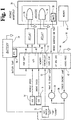
- FIG. 1 a diagrammatic illustration of a microprocessor controlled air intake heating and diagnostic system 10 embodying the present invention is shown.
- the battery 24 provides battery voltage to relays 32 and 34, key switch 22, "wait to start” lamp 36 and “check engine” lamp 38, as well as many other electrical vehicle components, (not shown).
- battery voltage is approximately 12-14 volts, but the system 10 of the present invention must be operable with battery voltages as low as 7 volts and as high as 24 volts.
- Key switch 22 is a three-position switch having an "off” position, an "on” position and a “crank” position. In the “off” position, key switch 22 disconnects battery voltage from the controller 12. In the “on” position, key switch 22 supplies battery voltage to the controller 12.
- key switch 22 In the "crank" position, key switch 22 further supplies battery voltage to an engine starter system (not shown) in order to start the engine.
- the three key positions, or states, described above for key switch 22 correspond to those normally encountered in a motor vehicle wherein the key switch is initially switched from the “off” position to the “run” position to supply power to the electrical system of a vehicle and upon further rotation of the switch to the "crank” position, a starter solenoid of the vehicle is engaged to start the engine.
- the key switch 22 just described is used in a preferred embodiment, the present invention contemplates other switch means for accomplishing the key switch function.
- a "software key", or software controlled system may be used to actuate a system of relays or other switches in order to supply battery voltage to the necessary electrical components.
- Controller 12 is a microcomputer including a microprocessor portion 42, an output driver portion 44 including output interface circuitry, a power supply portion 46, an analog-to-digital convertor portion 48, a memory portion 50 and a supporting circuitry portion 52.
- the microprocessor portion 42 runs software routines and manages the overall operation of the system 10.
- the microprocessor portion 42 may contain the analog-to digital convertor portion 48 for converting analog sensor signals to digital signals for further processing by the microprocessor portion 42.
- microprocessor portion 42 of controller 12 is a Motorolla 68336 microprocessor.
- the memory portion 50 of controller 12 may include ROM, RAM, EPROM, EEPROM, Flash PROM and any other reusable type of memory known to those skilled in the art.
- the memory portion 50 may be further supplemented by memory 40 connected thereto as shown by a dashed-line connection.
- Memory 40 may include any of the memory features described with respect to memory portion 50. Memory 40 may also be used to supplant memory portion 50 if controller 12 lacks a memory portion 50 or if memory portion 50 provides inadequate storage.
- the microprocessor portion 42 may include sufficient memory (including ROM and RAM) to obviate the need for memory portion 50 and/or supplemental memory 40.
- the power supply portion 46 of controller 12 receives electrical power from the battery 24 through key switch 22 when key switch 22 is in the "on" position, and supplies electrical power to the various controller portions as well as supporting circuitry which may be added to the system 10.
- the output driver portion 44 of controller 12 supplies power output signals capable of driving relays, switches and the like.
- the supporting circuitry portion 52 may include, for example, interface circuitry for conditioning input signals, a UART, load dump and electrostatic discharge (ESD) protection circuitry, buffer circuitry and other circuitry commonly associated with microcomputers.
- interface circuitry for conditioning input signals a UART, load dump and electrostatic discharge (ESD) protection circuitry, buffer circuitry and other circuitry commonly associated with microcomputers.
- ESD electrostatic discharge
- Heating elements 26 and 28 are located within the air intake manifold assembly 30. In a preferred embodiment, heating elements 26 and 28 are disposed adjacent to the intake manifold air inlet so that intake air is drawn over elements 26 and 28 before entering the intake manifold 30 during engine operation. Alternatively, heating elements 26 and 28 may be located inside the intake manifold 30 so that intake air is drawn into the engine through the intake manifold 30 and over elements 26 and 28 during operation of the engine. Heating elements 26 and 28, in a preferred embodiment, are rated at 1,050 watts, although the present invention contemplates using heating elements 26 and 28 rated as low as 500 watts and as high as 1,500 watts.
- Relays 32 and 34 connect heaters 26 and 28 to the battery 24, although another source of power, such as the alternator or an auxiliary power supply (not shown), may be used.
- the controller 12 activates or energizes relays 32 and 34, battery voltage is supplied to heaters 26 and 28, respectively.
- FIG. 1 shows two heating elements 26 and 28, the present invention contemplates using a variable number of heating elements depending on the engine model, type and usage. For example, some applications may require only a single heating element while others may call for as many as 8.
- controller 12 In addition to the switched battery voltage supplied to the controller 12 through the key switch 22, signals corresponding to battery temperature, intake manifold air temperature, vehicle speed and engine speed are supplied to inputs of controller 12.
- a battery temperature sensor (BTS) 18 provides the controller 12 with a signal corresponding to battery temperature.
- FIG. 1 shows BTS 18 as being attached to the battery 24, the present invention also contemplates locating BTS 18 within the battery 24 itself.
- An intake manifold air temperature sensor (IMATS) 20 is disposed within the intake manifold of the engine and provides controller 12 with a signal corresponding to the temperature of the air entering the intake manifold.
- An engine speed sensor (ESS) 16 supplies engine speed signals to controller 12 and is used to detect a stalled, cranking and running engine, as well as determined certain engine speed threshold levels discussed hereinafter.
- a stalled or stopped engine is defined as having an engine speed of less than 32 revolutions per minute (RPM).
- RPM revolutions per minute
- a cranking engine is defined as having an engine speed of greater than 32 RPM and less than 480 RPM
- a running engine is defined as having an engine speed above 480 RPM.
- a vehicle speed sensor (VSS) 14 provides controller 12 with a signal corresponding to the speed of the vehicle, and is used to establish an engine load threshold more fully described hereinafter.
- BTS 18, VSS 14, ESS 16 and IMATS 20 are analog sensors known in the automotive art.
- the present invention also contemplates using sensors that supply digital signals corresponding to the sensed parameter in order to accomplish the above-described functions. In so doing, the analog-to-digital convertor portion 48 of controller 12 is no longer necessary and may be omitted.
- the present invention further contemplates using redundant sensors within the system 10 so that the system 10 may remain fully operational while awaiting service on the failed or faulty sensor.
- Controller 12 further supplies signals to operator prompting device 36 and operator warning device 38.
- Operator prompting device 36 is a means for prompting the vehicle operator to wait for a predetermined preheat time period before starting the engine, after switching the key switch from the "off" position to the “on” position.
- Operator warning device 38 is a means for warning the operator of a fault or failure condition within the air intake heating system 10.
- Devices 36 and 38 are connected to the battery 24, or similar power source as described above with respect to the heaters 26 and 28, and are actuated by signals supplied by controller 12.
- the prompting means 36 is the "wait to start" lamp, as shown in FIG.
- the warning means 38 in a preferred embodiment, is the "check engine” lamp, as shown in FIG. 1, which is standard on most vehicles and is located within the instrument panel or cluster (not shown).
- the "check engine” lamp 38 is illuminated by the controller 12 to warn the vehicle operator of a fault condition within the intake air heating system, and continues to warn the operator until the key switch is returned to the "off" position.
- the "wait to start” lamp 36 or the “check engine” lamp 38 may be an incandescent lamp, any number of light emitting diodes (LEDs) or a combination of either type of light source with an optical waveguide.
- the present invention contemplates locating lamps 36 and 38 anywhere on the vehicle that may be observed by the vehicle operator while operating the vehicle.
- either device 36 or 38 may be, or include, an audible device for providing an audible signal, corresponding to the required function, to the vehicle operator.
- the controller 12 energizes or activates heaters 26 and 28 for a variable preheat time period prior to starting the engine in accordance with the initial temperature of the intake manifold air. If "preheat" is successfully completed, the controller 12 cycles heaters 26 and 28 after the engine has been started, for various time periods and duty cycles, for the duration of a postheat time period in accordance with the engine speed and initial temperature of the intake manifold air. Under certain conditions, more fully described hereinafter, the controller 12 continuously runs a heater diagnostic check during postheat to test the operation of heaters 26 and 28. If preheat is not successfully completed, the heater diagnostic check will be aborted.
- the controller 12 continuously executes a sensor diagnostics check from key switch 22 "on” to key switch 22 "off” to test each of the VSS 14, ESS 16, BTS 18 and IMATS 20 for faults and/or failures. Under certain failure or fault conditions, the vehicle operator is warned of the condition and certain sensor fault flags are set within memory portion 50 of controller 12.
- Controller 12 is powered up when key switch 22 is switched from the "off” position to the “on” position. Upon power up, controller 12 resets or initializes its air intake heating and diagnostic algorithm, illuminates the "wait to start” lamp 36, and begins to monitor all sensors for functionality.
- controller 12 If controller 12 senses an initial intake manifold air temperature (IMAT) below a predetermined temperature level for longer than a predetermined time period, controller 12 assumes that IMATS 20 is open-circuited and sets a temporary temperature sensor open-circuit (TSOC) flag within memory portion 50. On the other hand, if controller 12 senses an initial IMAT above another predetermined level for another predetermined time period, controller 12 assumes that IMATS 20 is short-circuited and sets a permanent temperature sensor short-circuit (TSSC) flag within memory portion 50. In a preferred embodiment, controller 12 detects an open-circuited IMATS 20 if the voltage supplied by IMATS 20 to the analog-to-digital portion 48 of controller 12 is below a valid lower threshold voltage level.
- IMAT intake manifold air temperature
- IMATS 20 voltage reading below the valid lower threshold voltage level may not correspond to an actual open-circuited IMATS, it is treated as such by the controller 12 since such an invalid voltage reading is indicative of an IMATS 20 fault condition.
- IMATS 20 voltages readings of below the valid lower threshold voltage level correspond to any temperature reading of below -40 degrees F.
- controller 12 detects a short-circuited IMATS 20 if the voltage supplied by IMATS 20 to the analog-to-digital portion 48 of controller 12 is above a valid upper threshold voltage level.
- an IMATS 20 voltage reading above the valid upper threshold voltage level may not correspond to an actual short-circuited IMATS, it is treated as such by the controller 12 since such an invalid voltage reading is indicative of an IMATS 20 fault condition.
- IMATS 20 voltages readings of above the valid upper threshold voltage level correspond to any temperature reading in excess of 250 degrees F.
- the controller 12 activates the "check engine” lamp 38 until the key switch 22 is returned to the "off” position only if a TSSC condition is detected.
- controller 12 activates the "check engine” lamp 38 until key switch 22 is returned to the "off” position in response to any invalid IMATS 20 voltage reading being detected by controller 12 for longer than 5 seconds,.
- the predetermined time period is set at 5 seconds in a preferred embodiment, the present invention contemplates predetermined time periods of between 0 and 64 seconds.
- the upper and lower predetermined temperature levels of 250 and -40 degrees F are limitations of the IMATS 20 itself and not of the present invention. As such, the present invention contemplates upper and lower predetermined temperature levels corresponding to the limits of the valid sensor voltage vs temperature characteristics of the particular IMATS 20 being used.
- the controller 12 flashes the "wait to start" lamp 36 at approximately 1 Hz until the preheat time period has expired.
- the invention contemplates flashing other lamps in response to the TSOC flag being set, including the "check engine” lamp 38 or other lamp observable by the vehicle operator. Further, the invention contemplates ramping the lamp illumination on and off as well as other flash or ramp rates. An important requirement of this feature is that the flashing or ramping of the lamp must be discernable by the vehicle operator in contrast to the continuous illumination of the lamp.
- Controller 12 further detects open-circuit and short-circuit failure conditions within BTS 18 and sets a battery temperature sensor fault (BTSF) flag within memory portion 50 in response to either.
- BTSF battery temperature sensor fault
- the BTS 18 open-circuit and short-circuit detection is performed identically to the open-circuit and short-circuit detection of IMATS 20 as previously discussed.
- controller 12 sets a vehicle speed sensor fault (VSSF) flag or engine speed sensor fault (ESSF) flag, respectively, within memory portion 50.
- the controller 12 activates the "check engine” lamp 38 if a BTSF, VSSF or ESSF flag is set within the memory portion 50.
- the present invention contemplates alternate embodiments wherein the "check engine” lamp 38 is activated in response to only certain ones of the BTSF, VSSF, ESSF, TSOC and TSSC flags being set, as well as further embodiments wherein only the foregoing flags are set in response to the corresponding fault being detected and the "check engine” lamp 38 is not activated in response thereto.
- the controller 12 determines that the initial IMAT reading is in excess of a preheat threshold temperature, then the controller 12 deactivates the "wait to start" lamp 36 and assumes that no intake manifold air preheating is necessary. In this case, heating elements 26 and 28 are not energized.
- the preheat threshold temperature in a preferred embodiment is 60 degrees F. If the initial IMAT is less than 60 degrees F the controller 12 determines a preheat schedule for energizing heaters 26 and 28 based upon the initial IMAT reading.
- Table 1 provides a suggested guide for determining the preheat schedule although other initial IMAT ranges, heater combinations, preheat durations and duty cycles are contemplated.
- IIMAT Initial Intake Manifold Air Temp.
- IIMAT (°F) PREHEAT SCHEDULE Heaters Duration
- Si Duty Cycle IIMAT ⁇ 0 Both 30 Continuous 0 ⁇ IIMAT ⁇ 16 Both 15 Continuous 16 ⁇ IIMAT ⁇ 60 Both 10 Continuous
- both heaters 26 and 28 are energized continuously for a preheat duration of 30 seconds. If IIMAT is greater than or equal to zero degrees F and less than 16 degrees F, both heaters 26 and 28 are energized continuously for a preheat duration of 15 seconds. Finally, if IIMAT is greater than or equal to 16 degrees F and less than 60 degrees F, both heaters 26 and 28 are energized continuously for a preheat duration of 10 seconds.
- the controller 12 assumes an initial IMAT reading in excess of 60 degrees F and the preheat schedule is aborted. If a TSOC flag was set with the initial IMAT reading, the controller assumes an initial IMAT reading of below zero degrees F and automatically selects the preheat schedule corresponding to IIMAT less than zero degrees F. If a TSOC flag is set at any time during the preheat schedule, the controller 12 extends the current preheat schedule to the preheat schedule corresponding to an initial IMAT reading of below 0 degrees F.
- the "wait to start” lamp 36 is flashed for the duration of the preheat schedule as previously discussed. If the controller 12 detects engine cranking (engine RPM greater than 32 RPM) at any time during the preheat schedule, the controller 12 sets an engine speed during preheat (ESDP) flag within the memory portion 50 and the remainder of the preheat schedule is aborted.
- engine cranking engine RPM greater than 32 RPM
- the controller 12 deactivates both heaters 26 and 28 and the "wait to start" lamp 36.
- Deactivating the "wait to start” lamp 36 by the controller 12 signals the vehicle operator to start the engine by switching the key switch 22 from the “on” position to the “crank” position until the engine is started. Once the engine is running, if the initial IMAT reading was less than 60 degrees F, a TSSC flag has not been set and the engine speed exceeds a postheat RPM level, postheat operation begins subject to further conditions determined by the controller 12 and described below.
- this feature is intended as a pre-delivery battery saver and the predetermined number may therefore be arbitrarily chosen. In a preferred embodiment, this predetermined number is chosen to be 25. Finally, if cranking has been detected for longer than a predetermined cranking time period, postheat will be aborted. This feature is also intended as a battery saver function and, although the predetermined cranking period may be between zero and 255 seconds, this period is set at 10 seconds in the preferred embodiment.
- a postheat RPM level of 480 RPM is used in a preferred embodiment. If the controller 12 fails to detect an engine speed exceeding 480 RPM within a predetermined engine speed timeout period, the controller 12 will set an engine speed timeout (ESTO) flag within the memory portion 50. In a preferred embodiment, this predetermined engine speed timeout period is 60 seconds although timeout periods of between 5 and 255 seconds are contemplated.
- ESO engine speed timeout
- the controller 12 determines the appropriate postheat schedule for cycling heaters 26 and 28 during the first few moments of engine operation.
- the postheat schedule is determined in accordance with the initial IMAT and current engine speed. Table 2 provides a suggested guide for determining the postheat schedule although other initial IMAT ranges, heater combinations, preheat durations and duty cycles are contemplated.
- both heaters 26 and 28 are continuously activated for 20 seconds. After 20 seconds have expired, one of the heaters, heater 26 for example, is continuously activated for 10 seconds while heater 28 is deactivated. After 10 seconds have expired, the other heater, heater 28 for example, is activated for 180 second at a 25% duty cycle while heater 26 is deactivated.
- both heaters 26 and 28 are continuously activated for 15 seconds. After 15 seconds have expired, one of the heaters, heater 26 for example, is activated for 195 seconds at a 25% duty cycle while heater 28 is deactivated, if the current engine speed is below 1500 RPM. If the engine speed is greater than 1500 RPM after the first 15 seconds have expired, one of the heaters, heater 26 for example, is activated continuously for 135 seconds while heater 28 is deactivated. After 135 seconds has elapsed, the other heater, heater 28 for example, is activated for 60 seconds at a 50% duty cycle while heater 26 is deactivated. If, at any time during the postheat schedule, the engine speed changes from less than 1500 RPM to greater than 1500 RPM, or vice versa, the controller 12 will activate the heaters 26 and 28 in accordance with the most recently detected engine speed.
- each of the foregoing duty cycles is based on a 10 second cycle.
- a 25% duty cycle corresponds to the appropriate heater being activated for 2.5 seconds and deactivated for 7.5 seconds
- a 50% duty cycle corresponds to the appropriate heater being activated for 5.0 seconds and deactivated for 5.0 seconds.
- the postheat time duration is approximately 210 seconds regardless of the IIMAT reading, the present invention contemplates variable postheat time durations based on IIMAT and current engine RPM levels.
- the controller 12 will continue postheat operation for the duration of the postheat time period. If, however, the engine speed falls below an engine stall threshold RPM level, postheat will be aborted to avoid consuming battery power. In a preferred embodiment, the engine is considered by the controller 12 to have stalled if the engine speed falls below 32 RPM. Postheat will also be aborted if the vehicle speed exceeds 10 MPH, since this condition will cause the engine to quickly achieve running temperature as previously explained. Finally, postheat will be aborted if, during the postheat time period, the ESS 16 fails resulting in the controller 12 setting the ESSF flag.
- the controller 12 continuously executes a heater diagnostics check for the duration of postheat to test the functionality of heaters 26 and 28.
- the conditions for executing the heater diagnostics check are determined by the controller 12 and are described below.
- the heater diagnostics check will be disabled by the controller 12. Similarly, if the initial IMAT reading is more than a predetermined temperature difference from the battery temperature, the controller 12 will disable the heater diagnostics check. This feature is included as a supplemental temperature verification and is intended to improve the reliability of the heater diagnostics check. If the battery temperature and initial IMAT are approximately equal, the controller 12 assumes that the engine is undergoing a "true" cold start. However, if the two temperatures are not close, the controller 12 assumes that the ambient air temperature is lower than the engine and the heater diagnostics check is disabled.
- this predetermined temperature difference is 10 degrees F although predetermined temperature differences of between zero and 255 degrees F are contemplated.
- the controller 12 continuously executes the heater diagnostics check as long as postheat operation continues.
- the controller 12 continuously compares the initial IMAT with the current IMAT value. If the absolute value of the difference between the two temperatures exceeds a predetermined heater diagnostic threshold temperature (HDTT) level for a predetermined time period, then the controller 12 sets a heater diagnostics test flag to "pass". However, if the absolute value of the difference between the two temperatures fails to exceed the HDTT level within the predetermined time period, the controller 12 will check the heater diagnostics test flag to determine whether it is set to "tempfail" for "temporary fail".
- HDTT heater diagnostic threshold temperature
- the controller 12 will set this flag to "tempfail”. If the heater diagnostic test flag is set to "tempfail”, this means that the controller 12 detected a heater fault or failure during operation of the engine prior to most recent switching of key switch 22 from the "off" position to the "on” position. In such a case, the controller 12 replaces the "tempfail” flag with a "permfail” flag, corresponding to a permanent fault flag, and further illuminates the "check engine” lamp 38 until the key switch 22 is returned to the "off” position.
- the controller 12 immediately illuminates the "check engine” lamp 38 until the key switch 22 is returned to the "off” state.
- the heater diagnostic test flag is an tri-state flag having the above-discussed states.
- the heater diagnostic test flag includes three distinct binary flags, those flags being a "pass” flag, a "permfail” flag and a "tempfail” flag.
- Table 3 provides a suggested guide for determining the heater diagnostic threshold temperature (HDTT) for the heater diagnostics check although other initial IMAT ranges and engine speed threshold values are contemplated.
- HDTT heater diagnostic threshold temperature
- HDTT HEATER DIAGNOSTIC TEMPERATURE THRESHOLD
- RPM RPM
- IIMAT IIMAT IIMAT ⁇ 0 0 ⁇ IIMAT ⁇ 16 16 ⁇ IIMAT ⁇ 60 ⁇ 1500 24 15 12 > 1500 12 10 8
- the controller 12 sets HDTT to 24 degrees F. If the engine speed is greater than 1500 RPM, the controller sets HDTT to 12 degrees F. If IIMAT is greater than or equal to zero degrees F and less than 16 degrees F, and the engine speed is below 1500 RPM, the controller 12 sets HDTT to 15 degrees F. If the engine speed is greater than 1500 RPM, the controller 12 sets HDTT to 10 degrees F. Finally, if IIMAT is greater than or equal to 16 degrees F and less than 60 degrees F, and the engine speed is less than 1500 RPM, the controller sets HDTT to 12 degrees F. If the engine speed is greater than 1500 RPM, the controller sets HDTT to 8 degrees F.
- the controller 12 deactivates both heaters 26 and 28 and checks whether a heater diagnostic test (HDT) flag has been set. If not, the controller 12 sets the HDT flag to "pass". Regardless of the status of the preheat, postheat, and heater diagnostics operations, the controller 12 continues to execute the sensor diagnostics check until the key switch 22 is returned to the "off" position.
- HDT heater diagnostic test
- the characteristics of another engine model may require defining a "running engine” as having an engine speed in excess of 850 RPM, or a preheat duration of 5 seconds when the initial intake manifold air temperature is greater than or equal to 60 degrees and less than 75 degrees.
- a common air intake heating and diagnostic system 10 for use with multiple engine models, types and usages is contemplated by the present invention.
- the controller 12 may include multiple sets of program data in EPROM, for example, for defining the above described numerical system parameters.
- a temporary flag is retained within memory portion 50 until the key switch 22 is returned to the "off" position.
- a permanent flag is retained within memory until erased during service of the air intake heating and diagnostic system.
- the TSOC flag for example, will be erased from memory portion 50 while the TSSC flag, for example, will remain within memory portion 50 until it is erased by service personnel.
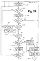
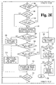
- FIG. 2A a flowchart depicting one embodiment of ⁇ n intake air heating and diagnostic algorithm according to the present invention is shown.
- Such an algorithm is executable by the microprocessor portion 42 of the controller 12 and is stored within the memory portion 50. All numerical values described in relation to this flow chart represent typical values and other values are contemplated by this invention as elsewhere noted.
- the program begins at step 200, and at step 202 the key switch 22 is tested to determine the key position or state. If at step 202 the key switch is not in the "on” position, the algorithm continuously executes step 202 until the key switch 22 is switched to the "on” position. When key “on " is detected, the algorithm advances to step 204 where the "wait to start” lamp 36 is activated.
- step 206 the status of the heater diagnostic test (HDT) flag is tested. If the HDT flag is set to "permfail”, the "check engine” lamp is activated at step 208. If the HDT flag is not set to "permfail” at step 206, the algorithm advances to step 210 where the sensor diagnostics subroutine of FIG. 3 is executed. The sensor diagnostics subroutine will be more fully described hereinafter. At step 212, if the intake manifold air temperature sensor was not detected as being short-circuited (permanent TSSC flag set) at step 210, the algorithm advances to step 248.
- HDT heater diagnostic test
- the initial intake manifold air temperature (initial IMAT) is compared to a value of 60 degrees F at step 214. If the initial IMAT is is greater than or equal to 60 degrees F, the algorithm advances to step 248. If the initial IMAT is less than 60 degrees F, the status of the temporary temperature sensor open-circuit (TSOC) flag is tested at step 216. If the TSOC flag is set, the algorithm advances to step 219. If the TSOC flag is not set, the initial IMAT is compared to a temperature value of zero degrees F at step 218. If the TSOC flag was found to be set at step 216, the "wait to start" lamp 36 is flashed at approximately 1 Hz at step 219.
- TSOC temporary temperature sensor open-circuit
- the preheat time period is set to 30 seconds at step 220. If the initial IMAT is greater than or equal to zero degrees F at step 218, the initial IMAT is compared to a temperature of 16 degrees F at step 222. If the initial IMAT is less than 16 degrees, the preheat time period is set to 15 seconds at step 224. If the initial IMAT is greater than or equal to 16 degrees at step 222, the preheat time period is set to 10 seconds at step 226 of FIG. 2B.
- the TSOC flag status is tested at step 228. If the TSOC flag is set, the algorithm advances to step 237. If the TSOC flag is not set at step 228, the sensor diagnostics subroutine of FIG. 3 is executed at step 230. At step 232, the status of the TSSC flag is tested. If a TSSC flag is set at step 230, the algorithm advances to step 248. If a TSSC flag was not set at step 230, the status of the TSOC is again tested at step 234. If the TSOC flag is set, the preheat time period is extended to 30 seconds at step 236.
- step 236 will have no effect. If, however, the preheat time period was originally set to 15 seconds at step 224, or to 10 seconds at step 226, the appropriate time period is added to the elapsed preheat time period to achieve a total preheat time period of 30 seconds. If the TSOC flag was set at step 228, or if the preheat time period was extended to 30 seconds at step 236, the "wait to start" lamp 36 is flashed at approximately 1 Hz at step 237.
- the TSOC flag is not set at step 234, or if flashing of the "wait to start" lamp 36 was commenced at step 237, the status of the engine speed sensor fault (ESSF) flag is tested at step 238. If the ESSF flag set at step 238, the algorithm advances to step 244. If the ESSF flag is not set, the engine speed is compared to a minimum engine speed cranking value of 32 RPM at step 240. If the engine speed is greater than 32 RPM (engine cranking), the engine speed during preheat (ESDP) flag is set at step 242 and the algorithm advances to step 248. If the engine speed is less than or equal to 32 RPM at step 240, both intake manifold air heaters 26 and 28 are activated at step 244. At step 246, the elapsed preheat time period is tested. If the preheat time period has not expired, the algorithm returns to step 228.
- the ESSF flag the engine speed is compared to a minimum engine speed cranking value of 32 RPM at step 240. If the engine
- both intake manifold air heaters 26 and 28 are deactivated at step 248.
- the "wait to start” lamp 36 is thereafter deactivated at step 250.
- the "continue at A” indicator 252 marks the end of the air intake heating and diagnostic preheat operation.
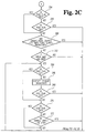
- the TSOC flag status is tested at step 254. If the TSOC flag is set, the algorithm continues at step 260. If the TSOC flag is not set at step 254, the status of the TSSC flag is tested at step 258. If a TSSC flag has been set, the algorithm continues at step 342. If a TSSC flag has not been set, or if the TSOC flag is set at step 254, the number of times the engine has been started since vehicle production is compared to a value of 25 at step 260. If the engine has been started less than 25 times, the algorithm continues at step 342. If the engine has been started 25 times or more, the initial IMAT is compared to a temperature value of 60 degrees F at step 262. If the initial IMAT was greater than or equal to 60 degrees F the algorithm continues at step 342. If the initial IMAT was less than 60 degrees F, the status of the TSOC flag is tested at step 264.
- the algorithm continues at step 270. If the TSOC flag is not set at step 264, the sensor diagnostics subroutine of FIG. 3 is executed at step 266. At step 268, the status of the TSSC flag is tested. If a TSSC flag was set at step 266, the algorithm continues at step 342. If a TSSC flag was not set at step 266, or if the TSOC flag was set at step 264, the status of the vehicle speed sensor fault (VSSF) flag is tested. If the VSSF flag is set at step 264, the algorithm continues at step 274. If the VSSF flag is not set, the vehicle speed is compared to a value of 10 MPH. If the vehicle speed is in excess of 10 MPH, the algorithm continues at step 342.
- VSSF vehicle speed sensor fault
- the vehicle speed is 10 MPH or less at step 272, or if the VSSF flag is set at step 270, the status of the ESSF flag is tested at step 274. If the ESSF flag is set, the algorithm continues at step 342. If the ESSF flag is not set, the engine speed is compared to the engine cranking speed window of greater than 32 RPM and less than 480 RPM at step 276. If the engine speed indicates cranking (engine speed between 32 RPM and 480 RPM) for longer than 10 seconds at step 278, the algorithm continues at step 342.
- the engine speed is compared to an engine running value of 480 RPM at step 280. If the engine speed is in excess of 480 RPM at step 280, the algorithm continues at step 288. If, at step 282, the engine speed is found to have been less than or equal to 480 RPM for longer than 60 seconds since the preheat time period expired, the engine speed timeout (ESTO) flag is set at step 284. If 60 seconds has not elapsed since the preheat time expired at step 282, or if the ESTO flag is set at step 284, the algorithm returns to step 264.
- ESTO engine speed timeout
- step 288 postheat operation begins at step 288 and the status of the TSOC flag is tested. If the TSOC flag, is set, the algorithm continues at step 294. IF the TSOC flag is not set at step 288, the sensor diagnostics subroutine of FIG. 3 is executed at step 290. At step 292, the status of the TSSC flag is tested. If a TSSC flag was set at step 290, the algorithm continues at step 342. If a TSSC flag was not set at step 290, or if the TSOC flag is set at step 288, the status of the ESSF flag is tested at step 294. If the ESSF flag is set at step 294, the algorithm continues at step 342. If the ESSF flag is not set, the engine speed is compared to an engine stall speed of 32 RPM at step 296.
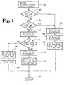
- the status of the VSSF flag is tested at step 298. If the VSSF flag is set at step 298, the algorithm continues at step 302. If the VSSF flag is not set at step 298, the vehicle speed is compared to a vehicle speed of 10 MPH at step 300. If the vehicle speed is in excess of 10 MPH, the algorithm continues at step 342. If the vehicle speed is less than or equal to 10 MPH, or if the VSSF flag was set at step 298, the postheat heater schedule (PHS) subroutine of FIG. 4 is executed at step 302. The PHS subroutine of FIG. 5 will be more fully described hereinafter.
- PHS postheat heater schedule
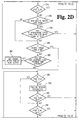
- both intake manifold air (IMA) heaters 26 and 28 are activated at step 306. If, at step 308, T1 has elapsed but the postheat time period T2 has not elapsed since the postheat schedule was determined at step 302, IMA heater 26 is deactivated and IMA heater 28 is activated according to a duty cycle determined within the PHS subroutine, at step 310.
- IMA intake manifold air
- IMA heater 28 is deactivated and IMA heater 26 is activated according to a duty cycle determined within the PHS subroutine, at step 314. If T3 has elapsed at step 312, then postheat is completed and the algorithm continues at step 342.
- the heater diagnostics check begins with testing the ESDP flag at step 315. If preheat was aborted due to engine cranking during preheat, thereby setting the ESDP flag, the algorithm continues from step 315 at step 288. If the ESDP flag is not set at step 315, program execution continues at step 316.
- the ESTO flag is tested at step 316. If the ESTO flag is set at step 316, the algorithm returns to step 288. If the ESTO flag is not set at step 316, the status of the battery temperature sensor fault (BTSF) flag is tested at step 318. If the BTSF flag is set, the algorithm returns to step 288. If the BTSF flag is not set, the most recently sensed battery temperature is compared to the initial IMAT reading at step 320. If, at step 320, the absolute value of the difference between the most recently sensed battery temperature and the initial IMAT reading is greater than or equal to 10 degrees F, the algorithm returns to step 288.
- BTSF battery temperature sensor fault
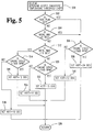
- the status of the TSOC flag is tested at step 322. If the TSOC flag is set at step 322, the algorithm returns to step 288. If the TSOC flag is not set, the status of the HDT flag is tested at step 324. If the HDT flag is set to "pass” or “permfail”, the algorithm returns to step 288. If the HDT flag is not set to either "pass” or "permfail", the heater diagnostic temperature threshold (HDTT) subroutine of FIG. 5 is executed at step 326. The HDTT subroutine of FIG. 5 will be more fully described hereinafter.
- HDTT heater diagnostic temperature threshold
- step 328 the initial IMAT is compared to the most recently sensed IMAT. If the absolute value of the difference between the initial IMAT and the most recently sensed IMAT is in excess of HDTT, the heater diagnostic test (HDT) flag is set to pass at step 330. If, at step 332, the absolute value of the difference determined in step 328 is less than or equal to HDTT for less than 10 seconds, or if the HDT flag is set to "pass" at step 330, the algorithm returns to step 288. If, at step 332, the absolute value of the difference determined in step 330 is less than or equal to HDTT for longer than 10 seconds, the status of the HDT flag is tested at step 334.
- HDT heater diagnostic test
- step 202 If the HDT flag was set to "tempfail” at key “on” (step 202), the "check engine” lamp 38 is activated at step 338 and the HDT flag is set to "permfail” at step 340. If, at step 334, the HDT flag was not set to "tempfail” at key “on” (step 202), the HDT flag is set to "tempfail” at step 336. After the HDT flag is set to "pass” at step 330, "tempfail” at 336 or “permfail” at step 340, the algorithm returns to step 288.
- the TSSC flag was set at steps 258, 268 or 292
- the engine was detected as having been started less than 25 times at step 260
- the initial IMAT was greater than or equal to 60 degrees F at step 262
- the vehicle speed was in excess of 10 MPH at steps 272 or 300
- the ESSF flag was set at steps 274 or 294
- the engine was cranking (engine speed greater than 32 RPM and less than 480 RPM) for more than 10 seconds at step 278, the engine speed was less than 32 RPM at step 296 or the postheat time period T3 had elapsed since PHS at step 312, then postheat was either completed or aborted and, in either case, both IMA heaters 26 and 28 are deactivated at step 342.
- step 344 the status of the HDT flag is tested. If the HDT flag was set (to "pass”, “tempfail” or “permfail” at steps 330, 336 or 340 respectively), the algorithm continues at step 348. If the HDT flag has not yet been set at step 344, the HDT flag is set to "pass” at step 346. If the HDT flag had been set at step 344, or if the HDT flag was set at step 346, the status of the key switch 22 is tested at step 348. If the key switch 22 is not "off", the sensor diagnostic subroutine of FIG. 3 is executed at step 350.
- the algorithm continuously alternates between testing the status of the key switch 22 at step 348 and executing the sensor diagnostics algorithm of FIG. 3 at step 350. If the key switch 22 is detected as being "off” at step 348, the algorithm terminates at step 352.
- the sensor diagnostics subroutine begins at step 360.
- the intake manifold air temperature (IMAT) is sensed.
- IMAT is compared to a temperature value of 250 degrees F. If IMAT is in excess of 250 degrees F, the subroutine continues at step 366.
- the subroutine returns to step 362. If, at step 366, IMAT has been in excess of 250 degrees for more than 5 seconds, an intake manifold air temperature sensor short-circuit condition (TSSC) exists and a permanent TSSC flag is set at step 368.
- TSSC intake manifold air temperature sensor short-circuit condition
- the "check engine” lamp 38 is thereafter activated at step 370.
- IMAT is not in excess of 250 degrees F at step 364, IMAT is compared to a temperature of -40 degrees F at step 372. If IMAT is less than -40 degrees F at step 372, the subroutine continues at step 374. If, at step 374, IMAT has been below -40 degrees F for less than 5 seconds, the subroutine returns to step 362. If, at step 374, IMAT has been below -40 degrees F for at least 5 seconds, an intake manifold air temperature sensor open-circuit condition (TSOC) exists and a temporary TSOC flag is set at step 376. The check engine lamp is thereafter activated at step 378. If, at step 372, IMAT is greater than or equal to -40 degrees F, the subroutine continues at step 380.
- TSOC intake manifold air temperature sensor open-circuit condition
- the engine speed is sensed at step 380. If, at step 382, the engine speed sensor is determined to be either open-circuited or short-circuited, the ESSF flag is set, and the "check engine” lamp 38 is activated, at step 384.
- step 382 If, at step 382, the engine speed sensor is neither open-circuited nor short-circuited, or if the ESSF flag is set at step 384, the vehicle speed is sensed at step 386. If, at step 388, the vehicle speed sensor is determined to be either open-circuited or short circuited, the VSSF flag is set, and the "check engine" lamp 38 is activated, at step 390.
- the battery temperature is sensed at step 392. If, at step 394, the battery temperature is determined to be less than or equal to -40 degrees F, or greater than or equal to 250 degrees F, the BTSF flag is set, and the "check engine" lamp 38 is activated, at step 396. If the battery temperature is greater than -40 degrees F and less than 250 degrees F at step 394, or if the BTSF flag is set at step 396, the subroutine returns to the algorithm of FIGS. 2A-2F at step 398.
- the postheat heater schedule subroutine begins at step 400, and at step 402 the status of the TSOC flag is tested. If the TSOC flag is set, the subroutine continues at step 406. If the TSOC flag is not set at step 402, the initial IMAT is compared to a temperature value of zero degrees F at step 404. If the initial IMAT is greater than or equal to zero degrees F, the subroutine continues at step 412. If the initial IMAT is less than zero degrees F at step 404, or if the TSOC flag was set at step 402, the postheat time period T1 is set to 20 seconds and the corresponding duty cycle is set to continuous, at step 406.
- the subroutine continues at step 408 where the postheat time period T2 is set at 10 seconds and the corresponding duty cycle is set to continuous.
- the subroutine continues at step 410 where the postheat time period T3 is set to 180 seconds and the corresponding duty cycle is set so that the appropriate IMA heater is continuously activated ("on") for 2.5 seconds and deactivated ("off") for 7.5 seconds.
- the T1 is set to 15 seconds and the corresponding duty cycle is set to continuous at step 412.
- the subroutine continues at step 414 where the engine speed is compared to an engine speed value of 1500 RPM. If the engine speed is greater than 1500 RPM, T2 is set to 135 seconds and the corresponding duty cycle is set to continuous at step 420.
- the subroutine continues then at step 422 where T3 is set to 60 seconds and the corresponding duty cycle is set so that the appropriate IMA heater is continuously activated ("on") for 5.0 seconds and deactivated ("off”) for 5.0 seconds.
- T2 is set at 195 seconds and the corresponding duty cycle is set so that the appropriate IMA heater is continuously activated ("on") for 2.5 seconds and deactivated ("off") for 7.5 seconds, at step 416.
- the subroutine then continues at step 418 where T3 is set to zero seconds. After T3 is set at step 410, 418 or 422, the subroutine returns to the algorithm of FIGS. 2A-2F at step 424.
- the heater diagnostic temperature threshold subroutine begins at step 500, and at step 502, the status of the TSOC flag is tested. If the TSOC flag is set, the subroutine continues at step 506. If the TSOC flag is not set at step 502, the initial IMAT is compared to a temperature value of zero degrees F at step 504. If the initial IMAT is greater than or equal to zero degrees F, the subroutine continues at step 512. If the initial IMAT is less than zero degrees F at step 504, or if the TSOC flag was set at step 502, the engine speed is compared to an engine speed value of 1500 RPM at step 506. If the engine speed is below 1500 RPM, HDTT is set to 24 degrees F. If the engine speed is above 1500 RPM at step 506, HDTT is set to 12 degrees F at step 510.
- the initial IMAT is compared to a temperature value of 16 degrees F at step 512. If the initial IMAT is greater than or equal to 16 degrees F, the subroutine continues at step 520. If the initial IMAT is less than 16 degrees F at step 512, the engine speed is compared to an engine speed value of 1500 RPM at step 514. If the engine speed is greater than or equal to 1500 RPM, the HDTT is set to 12 degrees F at step 516. If the engine speed is less than 1500 RPM at step 514, the HDTT is set to 10 degrees F at step 518.
- the engine speed is compared to an engine speed value of 1500 RPM at step 520. If the engine speed is greater than or equal to 1500 RPM, the HDTT is set to 15 degrees at step 522. If the engine speed is less than 1500 RPM at step 520, the HDTT is set to 10 degrees F at step 524. After the HDTT is set at step 508, 510, 516, 518, 522 or 524, the subroutine returns to the algorithm of FIGS. 2A-2F at step 526.
Landscapes
- Engineering & Computer Science (AREA)
- Chemical & Material Sciences (AREA)
- Combustion & Propulsion (AREA)
- Mechanical Engineering (AREA)
- General Engineering & Computer Science (AREA)
- Combined Controls Of Internal Combustion Engines (AREA)
- Electrical Control Of Air Or Fuel Supplied To Internal-Combustion Engine (AREA)
Applications Claiming Priority (3)
| Application Number | Priority Date | Filing Date | Title |
|---|---|---|---|
| US311562 | 1994-09-23 | ||
| US08/311,562 US5482013A (en) | 1994-09-23 | 1994-09-23 | Air intake heating and diagnostic system for internal combustion engines |
| EP95306692A EP0703360B1 (de) | 1994-09-23 | 1995-09-21 | Verfahren und Überwachungseinrichtung zur Fehlererkennung oder zum Warnen eines Fahrzeugführers für einen Fehler der Einlassluftheizvorrichtung |
Related Parent Applications (1)
| Application Number | Title | Priority Date | Filing Date |
|---|---|---|---|
| EP95306692A Division EP0703360B1 (de) | 1994-09-23 | 1995-09-21 | Verfahren und Überwachungseinrichtung zur Fehlererkennung oder zum Warnen eines Fahrzeugführers für einen Fehler der Einlassluftheizvorrichtung |
Publications (2)
| Publication Number | Publication Date |
|---|---|
| EP0965746A1 true EP0965746A1 (de) | 1999-12-22 |
| EP0965746B1 EP0965746B1 (de) | 2003-03-05 |
Family
ID=23207455
Family Applications (2)
| Application Number | Title | Priority Date | Filing Date |
|---|---|---|---|
| EP95306692A Expired - Lifetime EP0703360B1 (de) | 1994-09-23 | 1995-09-21 | Verfahren und Überwachungseinrichtung zur Fehlererkennung oder zum Warnen eines Fahrzeugführers für einen Fehler der Einlassluftheizvorrichtung |
| EP99117406A Expired - Lifetime EP0965746B1 (de) | 1994-09-23 | 1995-09-21 | Verfahren zur Fehlererkennung einer Einlassluftheizvorrichtung einer Fahrzeugbrennkraftmaschine, und Einlassluftheizvorrichtung und Überwachungsvorrichtung zur Verwendung in einer Fahrzeugbrennkraftmaschine |
Family Applications Before (1)
| Application Number | Title | Priority Date | Filing Date |
|---|---|---|---|
| EP95306692A Expired - Lifetime EP0703360B1 (de) | 1994-09-23 | 1995-09-21 | Verfahren und Überwachungseinrichtung zur Fehlererkennung oder zum Warnen eines Fahrzeugführers für einen Fehler der Einlassluftheizvorrichtung |
Country Status (3)
| Country | Link |
|---|---|
| US (1) | US5482013A (de) |
| EP (2) | EP0703360B1 (de) |
| DE (2) | DE69516474T2 (de) |
Cited By (4)
| Publication number | Priority date | Publication date | Assignee | Title |
|---|---|---|---|---|
| EP1136695A1 (de) * | 2000-03-17 | 2001-09-26 | IVECO FIAT S.p.A. | Diagnosesystem für die elektrische Heizvorrichtung eines zu einem Dieselmotor gehörigen Lüfteinlasskrümmers |
| RU2213251C2 (ru) * | 2001-07-30 | 2003-09-27 | Открытое акционерное общество "Муромский завод радиоизмерительных приборов" | Система управления предпусковым жидкостным подогревателем двигателя внутреннего сгорания |
| EP1505292A3 (de) * | 2003-08-05 | 2007-07-11 | ELTEK S.p.A. | Einrichtung zum Heizen eines in einem Kraftfahrzeug verwendeten Fluids, insbesondere eines Kraftstoffes |
| US9250156B2 (en) | 2012-09-27 | 2016-02-02 | Cummins Inc. | Techniques for evaluating performance of internal combustion engine components |
Families Citing this family (36)
| Publication number | Priority date | Publication date | Assignee | Title |
|---|---|---|---|---|
| US5655506A (en) * | 1995-09-25 | 1997-08-12 | Hollis; Thomas J. | System for preheating intake air for an internal combustion engine |
| US5634443A (en) * | 1995-11-20 | 1997-06-03 | Ford Motor Company | Method and system for controlling one of a glow plug heater system and a grid heater system in an automotive vehicle |
| DE19616651C2 (de) * | 1996-04-26 | 2000-04-13 | Deutz Ag | Kaltstarthilfe für Dieselmotoren |
| US5841112A (en) * | 1997-04-03 | 1998-11-24 | Whirlpool Corporation | Diagnostic display method for electronic cooking appliance control |
| US5844383A (en) * | 1997-07-15 | 1998-12-01 | Sundstrand Corporation | Gas turbine engine starting system and method |
| US6037573A (en) * | 1998-05-15 | 2000-03-14 | Ford Motor Company | System and method for controlling the operation of a heated wiper area |
| US6092496A (en) * | 1998-09-04 | 2000-07-25 | Caterpillar Inc. | Cold starting method for diesel engine with variable valve timing |
| US6091324A (en) * | 1998-11-13 | 2000-07-18 | Ford Motor Company | Comparing sensor outputs to distinguish between sensor faults and extreme temperature conditions |
| DE19854077C2 (de) * | 1998-11-24 | 2000-09-21 | Daimler Chrysler Ag | Verfahren zur Anwärmung der Ansaugluft |
| US6262400B1 (en) * | 2000-10-03 | 2001-07-17 | Delphi Technologies, Inc. | Control method for a resistance heater in a vehicle heating system |
| US6536419B2 (en) | 2001-05-04 | 2003-03-25 | Caterpillar Inc | Method and apparatus for preheating of combustion air for an internal combustion engine |
| US6718256B1 (en) * | 2001-10-04 | 2004-04-06 | Ford Global Technologies, Llc | Method for identifying an operating state of an engine soak timer |
| JP4210453B2 (ja) * | 2002-01-11 | 2009-01-21 | トヨタ自動車株式会社 | 車両の電子制御装置 |
| US6969855B2 (en) * | 2003-07-15 | 2005-11-29 | Ford Motor Company | Active night vision thermal control system |
| US7276696B2 (en) * | 2003-07-15 | 2007-10-02 | Ford Global Technologies, Llc | Active night vision thermal control system using wavelength-temperature characteristic of light source |
| EP1651911A4 (de) * | 2003-07-28 | 2010-09-01 | Phillips & Temro Ind Inc | Steuerung für einlassluftheizvorrichtung |
| EP1681457B2 (de) * | 2003-10-08 | 2017-04-19 | Nagares, S.A. | Modul zur erwärmung der einlassgase eines kraftfahrzeugmotors mit integrierter elektronischer temperaturregelung |
| JP4110149B2 (ja) * | 2005-04-01 | 2008-07-02 | 株式会社ホンダアクセス | グリップヒータ制御装置 |
| US20060243257A1 (en) * | 2005-04-13 | 2006-11-02 | Thermo King Corporation | Engine and method of operating the same |
| US7188597B2 (en) * | 2005-06-07 | 2007-03-13 | International Engine Intellectual Property Company, Llc | Engine cold start aid malfunction alert |
| JP2007120427A (ja) * | 2005-10-28 | 2007-05-17 | Fujitsu Ten Ltd | 始動制御装置 |
| US7581390B2 (en) * | 2006-04-26 | 2009-09-01 | Cummins Inc. | Method and system for improving sensor accuracy |
| US7660662B2 (en) * | 2006-12-28 | 2010-02-09 | Detroit Diesel Corporation | Fault code memory administrator with a driving cycle state machine concept |
| US8037872B2 (en) | 2007-05-31 | 2011-10-18 | Caterpillar Inc. | Engine system having cooled and heated inlet air |
| GB2449873B (en) * | 2007-06-05 | 2009-07-29 | Gm Global Tech Operations Inc | Hybrid drive system for a vehicle and method of operating a hybrid drive system |
| US20110030661A1 (en) * | 2009-08-04 | 2011-02-10 | International Engine Intellectual Property Company, Llc | Strategy for enabling intake air heater to clean up white smoke during warm engine re-start in cold weather |
| EP2525072B1 (de) * | 2011-05-16 | 2014-01-01 | Ford Global Technologies, LLC | Verfahren zur Erwärmung der Verbrennungsluft einer Brennkraftmaschine und Brennkraftmaschine zur Durchführung eines derartigen Verfahrens |
| JP5631824B2 (ja) * | 2011-08-31 | 2014-11-26 | 本田技研工業株式会社 | 発電機の出力制御装置 |
| EP2774011B8 (de) * | 2011-10-31 | 2018-06-27 | Glen Dimplex Americas Limited | Verfahren zur steuerung eines wärmeerzeugenden elements |
| DE102012011252A1 (de) * | 2012-06-06 | 2013-12-12 | Man Truck & Bus Ag | Steuerung eines elektrischen Ansaugluftvorwärmers einer Brennkraftmaschine |
| US20160153407A1 (en) * | 2013-07-03 | 2016-06-02 | Hidria Aet | Air intake heater system and methods |
| US20150114339A1 (en) * | 2013-10-31 | 2015-04-30 | Delphi Technologies, Inc. | Cold start strategy and system for gasoline direct injection compression ignition engine |
| CN103821655A (zh) * | 2014-03-04 | 2014-05-28 | 广西玉柴机器股份有限公司 | 发动机启动预热控制装置及其控制方法 |
| CN111913131B (zh) * | 2019-06-28 | 2023-08-25 | 中车大同电力机车有限公司 | 车辆加热监测系统 |
| CN114675625B (zh) * | 2022-03-21 | 2024-11-19 | 潍柴动力股份有限公司 | 一种控制器控制方法及装置 |
| CN119737237B (zh) * | 2024-12-10 | 2025-10-21 | 中国航空工业集团公司西安航空计算技术研究所 | 一种柴油发动机进气格栅加热控制方法及系统 |
Citations (6)
| Publication number | Priority date | Publication date | Assignee | Title |
|---|---|---|---|---|
| US4235215A (en) * | 1977-11-11 | 1980-11-25 | Daimler-Benz Aktiengesellschaft | Preliminary heating control installation for air-compressing internal combustion engines |
| US4782800A (en) * | 1987-08-24 | 1988-11-08 | Thermo King Corporation | Diesel engine control apparatus |
| US4924398A (en) * | 1986-09-25 | 1990-05-08 | Mitsubishi Denki Kabushiki Kaisha | Fault diagnosis system for automotive electronic devices |
| US5094198A (en) * | 1991-04-26 | 1992-03-10 | Cummins Electronics Company, Inc. | Air intake heating method and device for internal combustion engines |
| GB2251300A (en) * | 1990-12-22 | 1992-07-01 | Daimler Benz Ag | Process for heating the intake air in internal combustion engines by means of a flame starting system |
| EP0603796A2 (de) * | 1992-12-23 | 1994-06-29 | BERU Ruprecht GmbH & Co. KG | Flammstartanlage für eine Verbrennungseinrichtung |
Family Cites Families (22)
| Publication number | Priority date | Publication date | Assignee | Title |
|---|---|---|---|---|
| JPS6045757B2 (ja) * | 1978-07-10 | 1985-10-11 | いすゞ自動車株式会社 | ディ−ゼル・エンジンの予熱制御装置 |
| JPS5941014B2 (ja) * | 1979-02-24 | 1984-10-04 | マツダ株式会社 | エンジンの吸気装置 |
| JPS569636A (en) * | 1979-07-02 | 1981-01-31 | Nissan Motor Co Ltd | Temperature controller for internal combustion engine |
| JPS56121870A (en) * | 1980-03-03 | 1981-09-24 | Diesel Kiki Co Ltd | Preheating controller for diesel engine |
| US4545357A (en) * | 1983-11-22 | 1985-10-08 | Canadian Fram Limited | Programmable temperature control system |
| US4648364A (en) * | 1985-07-08 | 1987-03-10 | Wills William H | Engine protection apparatus |
| US4667645A (en) * | 1986-05-16 | 1987-05-26 | Ap Electronics, Inc. | Control device for diesel engine intake air heater and priming fluid injection system |
| DE3720683A1 (de) * | 1987-06-23 | 1989-01-05 | Bosch Gmbh Robert | Vorrichtung und verfahren zur ansteuerung und kontrolle von elektrischen verbrauchern, insbesondere gluehkerzen |
| JP2516188B2 (ja) * | 1988-09-22 | 1996-07-10 | 本田技研工業株式会社 | 温度センサの異常処理装置 |
| JPH0684743B2 (ja) * | 1989-06-20 | 1994-10-26 | 株式会社ユニシアジェックス | 熱線式エアフローメータの劣化検出装置 |
| US5113173A (en) * | 1989-07-03 | 1992-05-12 | William Lawson | Audible warning arrangement for supercharged internal combustion engine |
| KR910006053A (ko) * | 1989-09-06 | 1991-04-27 | 양갑수 | 차량용 히팅시스템의 오동작에 따른 자기진단 방법 및 그 표시회로 |
| JP2654706B2 (ja) * | 1990-02-16 | 1997-09-17 | トヨタ自動車株式会社 | 熱式吸入空気量センサ |
| JPH03244868A (ja) * | 1990-02-20 | 1991-10-31 | Mitsubishi Electric Corp | 自動変速機の油温センサ故障判定装置 |
| JP3024160B2 (ja) * | 1990-03-22 | 2000-03-21 | 日産自動車株式会社 | 蒸発燃料処理装置の故障診断装置 |
| US5046473A (en) * | 1990-04-19 | 1991-09-10 | Onan Corporation | Automatic air intake temperature regulator apparatus and method |
| EP0463953B1 (de) * | 1990-06-29 | 1996-03-27 | Suzuki Motor Corporation | Übertemperaturdetektorgerät für Motor |
| DE4029811C2 (de) * | 1990-09-20 | 1999-08-12 | Bosch Gmbh Robert | Katalysatorheizfunktion |
| GB2251962B (en) * | 1990-11-13 | 1995-05-24 | Samsung Heavy Ind | System for automatically controlling an operation of a heavy construction |
| DE4039598B4 (de) * | 1990-12-12 | 2008-11-27 | Robert Bosch Gmbh | Heißstartverfahren und -Vorrichtung für eine Brennkraftmaschine |
| JPH04241775A (ja) * | 1991-01-17 | 1992-08-28 | Sanshin Ind Co Ltd | エンジンの点火進角制御装置 |
| US5070832A (en) * | 1991-03-29 | 1991-12-10 | Cummins Engine Company, Inc. | Engine protection system |
-
1994
- 1994-09-23 US US08/311,562 patent/US5482013A/en not_active Expired - Lifetime
-
1995
- 1995-09-21 DE DE69516474T patent/DE69516474T2/de not_active Expired - Lifetime
- 1995-09-21 DE DE69529853T patent/DE69529853T2/de not_active Expired - Fee Related
- 1995-09-21 EP EP95306692A patent/EP0703360B1/de not_active Expired - Lifetime
- 1995-09-21 EP EP99117406A patent/EP0965746B1/de not_active Expired - Lifetime
Patent Citations (6)
| Publication number | Priority date | Publication date | Assignee | Title |
|---|---|---|---|---|
| US4235215A (en) * | 1977-11-11 | 1980-11-25 | Daimler-Benz Aktiengesellschaft | Preliminary heating control installation for air-compressing internal combustion engines |
| US4924398A (en) * | 1986-09-25 | 1990-05-08 | Mitsubishi Denki Kabushiki Kaisha | Fault diagnosis system for automotive electronic devices |
| US4782800A (en) * | 1987-08-24 | 1988-11-08 | Thermo King Corporation | Diesel engine control apparatus |
| GB2251300A (en) * | 1990-12-22 | 1992-07-01 | Daimler Benz Ag | Process for heating the intake air in internal combustion engines by means of a flame starting system |
| US5094198A (en) * | 1991-04-26 | 1992-03-10 | Cummins Electronics Company, Inc. | Air intake heating method and device for internal combustion engines |
| EP0603796A2 (de) * | 1992-12-23 | 1994-06-29 | BERU Ruprecht GmbH & Co. KG | Flammstartanlage für eine Verbrennungseinrichtung |
Cited By (5)
| Publication number | Priority date | Publication date | Assignee | Title |
|---|---|---|---|---|
| EP1136695A1 (de) * | 2000-03-17 | 2001-09-26 | IVECO FIAT S.p.A. | Diagnosesystem für die elektrische Heizvorrichtung eines zu einem Dieselmotor gehörigen Lüfteinlasskrümmers |
| RU2213251C2 (ru) * | 2001-07-30 | 2003-09-27 | Открытое акционерное общество "Муромский завод радиоизмерительных приборов" | Система управления предпусковым жидкостным подогревателем двигателя внутреннего сгорания |
| EP1505292A3 (de) * | 2003-08-05 | 2007-07-11 | ELTEK S.p.A. | Einrichtung zum Heizen eines in einem Kraftfahrzeug verwendeten Fluids, insbesondere eines Kraftstoffes |
| EP2075452A3 (de) * | 2003-08-05 | 2009-09-02 | Eltek S.p.A. | Einrichtung zum Heizen eines in einem Kraftfahrzeug verwendeten Fluids, insbesondere eines Kraftstoffes |
| US9250156B2 (en) | 2012-09-27 | 2016-02-02 | Cummins Inc. | Techniques for evaluating performance of internal combustion engine components |
Also Published As
| Publication number | Publication date |
|---|---|
| DE69529853D1 (de) | 2003-04-10 |
| DE69516474D1 (de) | 2000-05-31 |
| EP0965746B1 (de) | 2003-03-05 |
| DE69529853T2 (de) | 2003-09-25 |
| EP0703360A3 (de) | 1996-12-11 |
| DE69516474T2 (de) | 2000-09-07 |
| EP0703360B1 (de) | 2000-04-26 |
| US5482013A (en) | 1996-01-09 |
| EP0703360A2 (de) | 1996-03-27 |
Similar Documents
| Publication | Publication Date | Title |
|---|---|---|
| EP0703360B1 (de) | Verfahren und Überwachungseinrichtung zur Fehlererkennung oder zum Warnen eines Fahrzeugführers für einen Fehler der Einlassluftheizvorrichtung | |
| AU632968B2 (en) | Air intake heating method and device for internal combustion engines | |
| US7091629B2 (en) | Engine control system and method of automatic starting and stopping a combustion engine | |
| JP2607347B2 (ja) | 内燃機関エンジンのための速度対応吸気口システム及びその方法 | |
| BRPI0506014B1 (pt) | Método para controle do modo "parada-e-partida" em um veículo motor equipado com um motor de combustão interna | |
| CN101397969B (zh) | 内燃机控制装置 | |
| US20030052486A1 (en) | Device and method for control of motor vehicle engine idle rpm to prevent disruptive battery discharge | |
| CN101595285B (zh) | 内燃机的二次空气供应设备以及该二次空气供应设备的控制方法 | |
| US20070073470A1 (en) | Apparatus for and method of controlling a vehicle | |
| US20210164391A1 (en) | Fuel gelling prevention using engine auto start functionality | |
| RU2717350C2 (ru) | Способ очистки загрязненной свечи зажигания двигателя автомобиля (варианты) и система автомобиля | |
| JPH08505201A (ja) | 内燃機関における燃料供給システムの充填方法 | |
| JP2003519741A (ja) | エンジン制御方法 | |
| US7188597B2 (en) | Engine cold start aid malfunction alert | |
| JP4828887B2 (ja) | 内燃機関の始動制御装置 | |
| JP2009191743A (ja) | 異常判定装置 | |
| JP3488086B2 (ja) | エンジン制御装置および制御方法 | |
| KR19990073267A (ko) | 엘피지와가솔린겸용차량의연료전환방법및그시스템 | |
| JPH1122529A (ja) | エンジンの制御装置 | |
| KR19990068507A (ko) | 엘피지와가솔린겸용차량의연료전환방법및그시스템 | |
| JP3005860B1 (ja) | エンジン自動始動方法及び装置 | |
| JP2537057Y2 (ja) | 内燃機関停止装置 | |
| JPH11190680A (ja) | エンジンの試験装置 | |
| JP2003118356A (ja) | 自動車補助ヒータ | |
| JPH0441255Y2 (de) |
Legal Events
| Date | Code | Title | Description |
|---|---|---|---|
| PUAI | Public reference made under article 153(3) epc to a published international application that has entered the european phase |
Free format text: ORIGINAL CODE: 0009012 |
|
| AC | Divisional application: reference to earlier application |
Ref document number: 703360 Country of ref document: EP |
|
| AK | Designated contracting states |
Kind code of ref document: A1 Designated state(s): DE GB |
|
| AX | Request for extension of the european patent |
Free format text: AL;LT;LV;MK;RO;SI |
|
| 17P | Request for examination filed |
Effective date: 20000422 |
|
| AKX | Designation fees paid |
Free format text: DE GB |
|
| 17Q | First examination report despatched |
Effective date: 20010305 |
|
| GRAH | Despatch of communication of intention to grant a patent |
Free format text: ORIGINAL CODE: EPIDOS IGRA |
|
| GRAH | Despatch of communication of intention to grant a patent |
Free format text: ORIGINAL CODE: EPIDOS IGRA |
|
| GRAA | (expected) grant |
Free format text: ORIGINAL CODE: 0009210 |
|
| AC | Divisional application: reference to earlier application |
Ref document number: 0703360 Country of ref document: EP Kind code of ref document: P |
|
| AK | Designated contracting states |
Designated state(s): DE GB |
|
| REG | Reference to a national code |
Ref country code: GB Ref legal event code: FG4D |
|
| REF | Corresponds to: |
Ref document number: 69529853 Country of ref document: DE Date of ref document: 20030410 Kind code of ref document: P |
|
| RAP2 | Party data changed (patent owner data changed or rights of a patent transferred) |
Owner name: CUMMINS INC. |
|
| PLBE | No opposition filed within time limit |
Free format text: ORIGINAL CODE: 0009261 |
|
| STAA | Information on the status of an ep patent application or granted ep patent |
Free format text: STATUS: NO OPPOSITION FILED WITHIN TIME LIMIT |
|
| 26N | No opposition filed |
Effective date: 20031208 |
|
| PGFP | Annual fee paid to national office [announced via postgrant information from national office to epo] |
Ref country code: GB Payment date: 20070926 Year of fee payment: 13 |
|
| PGFP | Annual fee paid to national office [announced via postgrant information from national office to epo] |
Ref country code: DE Payment date: 20071031 Year of fee payment: 13 |
|
| GBPC | Gb: european patent ceased through non-payment of renewal fee |
Effective date: 20080921 |
|
| PG25 | Lapsed in a contracting state [announced via postgrant information from national office to epo] |
Ref country code: DE Free format text: LAPSE BECAUSE OF NON-PAYMENT OF DUE FEES Effective date: 20090401 |
|
| PG25 | Lapsed in a contracting state [announced via postgrant information from national office to epo] |
Ref country code: GB Free format text: LAPSE BECAUSE OF NON-PAYMENT OF DUE FEES Effective date: 20080921 |