EP0965837A1 - Verfahren zur Messung der relativen Feuchtigkeit, insbesondere für Radiosonden, und Feuchtigkeitssensoren dazu - Google Patents
Verfahren zur Messung der relativen Feuchtigkeit, insbesondere für Radiosonden, und Feuchtigkeitssensoren dazu Download PDFInfo
- Publication number
- EP0965837A1 EP0965837A1 EP99109901A EP99109901A EP0965837A1 EP 0965837 A1 EP0965837 A1 EP 0965837A1 EP 99109901 A EP99109901 A EP 99109901A EP 99109901 A EP99109901 A EP 99109901A EP 0965837 A1 EP0965837 A1 EP 0965837A1
- Authority
- EP
- European Patent Office
- Prior art keywords
- detector
- humidity
- heating
- detectors
- capacitance
- Prior art date
- Legal status (The legal status is an assumption and is not a legal conclusion. Google has not performed a legal analysis and makes no representation as to the accuracy of the status listed.)
- Granted
Links
- 238000005259 measurement Methods 0.000 title claims abstract description 56
- 238000000034 method Methods 0.000 title claims abstract description 31
- 238000010438 heat treatment Methods 0.000 claims abstract description 102
- XLYOFNOQVPJJNP-UHFFFAOYSA-N water Substances O XLYOFNOQVPJJNP-UHFFFAOYSA-N 0.000 claims abstract description 18
- 239000000463 material Substances 0.000 claims abstract description 6
- 239000003990 capacitor Substances 0.000 claims abstract description 3
- 230000008878 coupling Effects 0.000 claims abstract description 3
- 238000010168 coupling process Methods 0.000 claims abstract description 3
- 238000005859 coupling reaction Methods 0.000 claims abstract description 3
- 238000010276 construction Methods 0.000 claims description 12
- 230000033228 biological regulation Effects 0.000 claims description 8
- 239000000758 substrate Substances 0.000 claims description 8
- 230000008859 change Effects 0.000 claims description 7
- 238000007710 freezing Methods 0.000 claims description 5
- 230000008014 freezing Effects 0.000 claims description 5
- 230000015572 biosynthetic process Effects 0.000 claims description 4
- 239000011810 insulating material Substances 0.000 claims description 4
- 238000009736 wetting Methods 0.000 claims description 2
- 238000009413 insulation Methods 0.000 claims 1
- 238000004804 winding Methods 0.000 claims 1
- 230000001105 regulatory effect Effects 0.000 description 6
- 230000008901 benefit Effects 0.000 description 5
- 238000004519 manufacturing process Methods 0.000 description 5
- 238000010586 diagram Methods 0.000 description 4
- 238000012545 processing Methods 0.000 description 4
- 239000004020 conductor Substances 0.000 description 3
- 230000001419 dependent effect Effects 0.000 description 2
- 230000001627 detrimental effect Effects 0.000 description 2
- 239000011521 glass Substances 0.000 description 2
- 238000012986 modification Methods 0.000 description 2
- 230000004048 modification Effects 0.000 description 2
- BASFCYQUMIYNBI-UHFFFAOYSA-N platinum Chemical compound [Pt] BASFCYQUMIYNBI-UHFFFAOYSA-N 0.000 description 2
- 229920006254 polymer film Polymers 0.000 description 2
- 230000005855 radiation Effects 0.000 description 2
- 238000010420 art technique Methods 0.000 description 1
- 238000001816 cooling Methods 0.000 description 1
- 238000012937 correction Methods 0.000 description 1
- 238000011161 development Methods 0.000 description 1
- 230000000694 effects Effects 0.000 description 1
- 238000005485 electric heating Methods 0.000 description 1
- 230000005611 electricity Effects 0.000 description 1
- PCHJSUWPFVWCPO-UHFFFAOYSA-N gold Chemical compound [Au] PCHJSUWPFVWCPO-UHFFFAOYSA-N 0.000 description 1
- 239000010931 gold Substances 0.000 description 1
- 229910052737 gold Inorganic materials 0.000 description 1
- 230000010354 integration Effects 0.000 description 1
- 239000000155 melt Substances 0.000 description 1
- 229920000620 organic polymer Polymers 0.000 description 1
- 230000000737 periodic effect Effects 0.000 description 1
- 229920006255 plastic film Polymers 0.000 description 1
- 239000002985 plastic film Substances 0.000 description 1
- 229910052697 platinum Inorganic materials 0.000 description 1
- 230000009467 reduction Effects 0.000 description 1
- 230000002441 reversible effect Effects 0.000 description 1
- 230000000630 rising effect Effects 0.000 description 1
- 230000006641 stabilisation Effects 0.000 description 1
- 238000011105 stabilization Methods 0.000 description 1
- 238000012546 transfer Methods 0.000 description 1
Images


Classifications
-
- G—PHYSICS
- G01—MEASURING; TESTING
- G01W—METEOROLOGY
- G01W1/00—Meteorology
- G01W1/08—Adaptations of balloons, missiles, or aircraft for meteorological purposes; Radiosondes
-
- G—PHYSICS
- G01—MEASURING; TESTING
- G01N—INVESTIGATING OR ANALYSING MATERIALS BY DETERMINING THEIR CHEMICAL OR PHYSICAL PROPERTIES
- G01N27/00—Investigating or analysing materials by the use of electric, electrochemical, or magnetic means
- G01N27/02—Investigating or analysing materials by the use of electric, electrochemical, or magnetic means by investigating impedance
- G01N27/22—Investigating or analysing materials by the use of electric, electrochemical, or magnetic means by investigating impedance by investigating capacitance
- G01N27/223—Investigating or analysing materials by the use of electric, electrochemical, or magnetic means by investigating impedance by investigating capacitance for determining moisture content, e.g. humidity
- G01N27/225—Investigating or analysing materials by the use of electric, electrochemical, or magnetic means by investigating impedance by investigating capacitance for determining moisture content, e.g. humidity by using hygroscopic materials
Definitions
- the invention concerns a method for measurement of relative humidity according to the preamble of claim 1.
- the invention concerns also a capacitive humidity detector according to the preamble of claim 6.
- capacitive detectors are used, which are usually based on the fact that the permittivity of the insulating material between the capacitor plates is dependent on the temperature, in which case the capacitance detected from the terminals of the detector also depends on the temperature.
- the FI Patent No. 48,229 is related to the prior art concerned in the present invention, in which patent a capacitive humidity detector is described in which the dielectric insulating material is a polymer film, whose permittivity is a function of the amount of water absorbed by the polymer film.
- FI Patent No. 58,402 a method is described for reduction of undesirable properties produced by reversible changes in an electric humidity detector based on change in impedance, in particular in a capacitive humidity detector, in which the material sensitive to humidity is an organic polymer, which is heated, at least with higher relative humidities, to a temperature higher than the temperature in the environment of the humidity detector. If necessary, the heating power of the detector can be regulated as a function of the humidity to be measured.
- the temperature of the humidity detector and/or the outside temperature is/are measured, and this or these auxiliary quantities are utilized in the computing of the humidity measurement values.
- a regulating device in a humidity detector which comprises a bridge connection or equivalent, which includes temperature-dependent resistor elements, by whose means the temperature outside the detector and the temperature T s of the detector itself are detected, the differential voltage in said bridge connection being used as a feedback signal, by whose means the electric power that heats the detector is regulated.
- a heating resistor of the detector such a resistor element of positive temperature coefficient is used, for example a platinum resistor, as operates at the same time as the sensor of the temperature T s of the detector.
- thermocouple in which the connection of one branch of its thermoelements is placed in connection with, or at the proximity of, the detector to be measured, and in which thermocouple the connection of the other branch is placed in the atmosphere surrounding the detector, and in which method, by means of said thermocouple, the difference between the temperature prevailing in connection with the detector and the temperature of the surrounding atmosphere is observed, an electric signal that represents said difference acting upon the output signal of the measurement coupling of the radiosonde, which signal includes the information on the meteorological quantity or quantities to be measured by means of the detector or detectors.
- the general object of the present invention is further development of the prior-art technique of measurement of relative humidity, in particular in radiosonde applications, so that the drawbacks, to be described in more detail later, are avoided.
- the capacitive humidity detector is subjected to such a high humidity that the detector operation deteriorates and water, frost, and/or ice is/are gathered and condensed on the active face of the detector or on the structures in its environment.
- the principal object of the invention is to provide a humidity detector by whose means it is possible to avoid the drawbacks produced by condensing and freezing of water on the face of the humidity detector and/or on the structures in its environment, for example, when a radiosonde flies in a supercooled cloud.
- the object of the invention is to provide a method of measurement and a detector by whose means relative humidity can be measured at least at the precision of ⁇ 1...2 % mentioned above. It is a further object of the invention to provide a method of measurement and a detector that is particularly well suitable for disposable radiosondes, so that, by means of the method and the detectors of the invention, the detector arrangement can be made simple, of low weight and, in large-volume production, also otherwise economical.
- the method of the invention is mainly characterized by the characterizing part of claim 1.
- the detector in accordance with the invention is mainly characterized by the characterizing part of claim 6.
- the stage of measurement of the detector temperature and the equipment and computing arrangements necessary for said stage can be omitted completely, as a result of which the steps of carrying out of the method and the detector constructions and the related other systems are simplified substantially and, yet, the above accuracy of measurement is achieved, which is, as a rule, adequate in sonde operation.
- heating energy expressly electric current is used, preferably direct current, which is passed, in accordance with the method of the invention, into a resistive heating resistor or into different combinations of heating resistors placed in connection with the detector or combination of detectors.
- the heating of the humidity detector is needed in order to remove any frost, ice and water, which is detrimental in view of the measurement of humidity, from the detector.
- the detector assembly consists of a part that measures the humidity and of a heating part. These may be separate constructions, or some construction of the humidity measurement may also be used for heating. If necessary, the heating capacity may also be regulated in various ways.
- measurement and regulation electronics may be used as an addition to an ordinary sonde application.
- the heating element itself may operate as the detector of the heating requirement so that ice and/or condensed water produce(s) a change in the heating rate of the element, and the slowing down of the specific resistance of the resistor piece in the element is measured by means of the electronics.
- the electronic system allows the heating to be continued or switches if off, as necessary.
- the heating cycle can be carried out once during one measurement cycle of the sonde, or otherwise.
- the heating capacity can be regulated when necessary. If necessary, the magnitude of the capacity can be measured, for example, by means of a resistor that is heated simultaneously with the heating. This information can also be used as a measure of freezing efficiency or of supersaturation.
- a preferred embodiment of the humidity detector in accordance with the invention is characterized by its small size and construction so that a short-time heating pulse spreads to the surface electrode and to its vicinity only.
- the thermal time constant and the humidity time constant of the detector are very short and permit the use of the detector for measurement of humidity directly without correction of errors arising from heating in sonde operation, in which the measurement of humidity takes place, as is known from the prior art, once in about 1.5 seconds.
- the heating removes any ice and water that interferes with the measurement from the face and/or the vicinity of the humidity detector.
- the small size of the detector makes the use of radiation protection unnecessary. The cost of manufacture of the detector can also be made lower than with the prior-art detectors.
- the invention it is possible to use two physically separate detectors or an integrated pair of detectors that are thermally insulated from one another, so that one detector is heated while the relative humidity is being measured by means of the other one, and the other way round, alternatingly.
- heating By means of heating, the ice and water detrimental to the measurement of humidity are removed from the detector.
- the use of a detector that has been heated but has not yet become sufficiently cool for measurements of humidity is avoided, and awkward measurements of the detector temperature and difficulties in compensation computing are eliminated.
- a possibility is provided for many sorts of timing of heating and regulation of heating capacity. The detector does not have to be so extremely rapid as when pulse heating of one detector is applied, even if the use of this is also possible.
- a detector that is best suitable for this use is a detector heated by means of a bottom electrode, in which an advantage is the making of the heating resistor in an integrated way in connection with the manufacture of the humidity detector.
- the thermal time constant and the humidity time constant can be made sufficiently short, the transfer of heat becomes good, and the application of the heating capacity to the correct area becomes correct.
- Small size and integration bring economies of cost in the manufacture.
- modifications are required in comparison with the prior an sonde electronics, because the detectors are connected alternatingly to heating or to humidity measurement. If necessary, the heating may also be regulated in different ways. An electronic system that measures both of the humidity detectors constantly is also possible.
- the heating alone is alternated, and the correct humidity is distinguished by means of data processing based on the fact that a warm detector shows a lower reading. It is also possible to use one detector so that it is heated in between, and the incorrect data are rejected and the interpolated "correct" data are substituted for the rejected data.
- the humidity detector according to the invention is carried out so that several component detectors that measure humidity are connected in parallel.
- the measurement of relative humidity takes place under parallel connection across all of the capacitive humidity detectors preferably constantly.
- Each component detector is heated separately one at a time.
- the error produced by the heating is always reduced to one part per N of the error of one component detector when N component detectors are connected in parallel.
- the error is reduced further when the detector assembly is calibrated while said heating is in operation normally.
- the electronic system is needed for the heating and for carrying out the measurement.
- Such connecting in parallel of detectors can be accomplished with detectors based on the heating of a surface electrode or of a bottom electrode.
- the applicant's prior-art "Humicap"TM construction is possible if supplemented with a heating resistor, which is either vapour-deposited on the substrate or a resistor piece.
- the humidity detectors can be integrated on one or several substrates.
- the advantage is also obtained that various electrical phenomena related to the electric current used for the heating do not interfere with the measurement of the detector capacitance, which is also important in the respect that said detector capacitances used in measurements of relative humidity are quite low, their capacitance value being, as a rule, in the range of 1...100 pf.
- the humidity detector shown in Figs. 1A and 1B is constructed on a stable glass substrate 10, onto one of whose plane faces the electrode 13a of the detector capacitance is applied, onto which electrode a plastic film 12 is fitted whose permittivity is a function of the amount of water absorbed by the film 12.
- a surface electrode film 14 is applied, which is penetrable by water but, yet, electrically conductive and which is in galvanic connection with a surface contact 13b.
- the capacitance C M to be measured is detected between the terminals c 1 and c 2 connected to the contacts 13a and 13b.
- the detector 10 as shown in Figs.
- the electric heating current I preferably direct current, can be passed through the terminals r 1 and r 2 connected to the contact patterns 15a and 15b.
- the electric equivalent circuit of the humidity detector 10 as shown in Figs. 1A and 1B is illustrated in Fig. 1C.
- FIGS 2A and 2B show a second humidity detector 10 in accordance with the invention, in which no separate heating resistor is used, but the heating resistor R consists of an electrically conductive surface electrode 14.
- the surface electrode 14 is a very thin, "perforated" film penetrable by moisture and made, e.g., of gold, which film is, however, electrically continuous and, thus, also electrically conductive.
- Figs. 3A and 3B show a detector 10 that is in the other respects similar to Figs. 1A and 1B except that the heating resistor 15 is placed on the opposite face of the glass substrate 11 in relation to the electrodes 13a, 14 and to the active film 12.
- the equivalent circuit of the humidity detector as shown in Figs. 3A and 3B is similar to that shown in Fig. 1C.
- the measures 1 x m x s of the detectors shown in Figs. 1, 2 and 3 are relatively little, so that both the size and the thermal mass of the detector can be made little and, thus, such that it is heated and cooled sufficiently rapidly.
- the dimensions 1 x m x s given above are ⁇ 4 mm x 1.5 mm x 0.2 mm.
- a detector 10 in accordance with the invention is shown that is attached to support strips 16a and 16b, which are made of an insulating material.
- a resistor wire 15 is wound, which forms the resistor R that heats the detector, the heating current I being passed to the terminals r 1 and r 2 of said resistor R.
- Figs. 5A and 5B show a heated detector construction which is in the other respects similar to that shown in Figs. 4A and 4B except that the active detector 10 is attached to a unified strip 16, around which, like around the detector 10, a resistor wire 15 is wound, which forms the heating resistor R of the detector 10.
- the electric equivalent circuit of the detectors as shown in Figs. 4 and 5 is similar to that shown in Fig. 1C.
- the detector 10 proper, the heating resistor 15, and its possible support constructions 16a, 16b are, differing from Figs. 1 to 3, constructions separate from one another and manufactured in different stages of manufacture.
- a particular advantage of the constructions as shown in Figs. 1 to 3 is their small size and low thermal mass, which are of substantial advantage in a number of different applications of the invention, as will come out in more detail later.
- Fig. 6 shows a detector assembly 10P in accordance with the invention in which there are N component detector capacitances C 1 ...C N , which are connected in parallel with one another.
- the capacitance C M to be measured can be detected constantly.
- the heating of the different component capacitances C 1 ...C N is carried out alternatingly so that one component capacitance C 1 ...C N is always heated while the other capacitances are cooling at the same time.
- the error produced by the heating is lowered to one part per N, and yet, from the active face of each component capacitance, the frost and ice can be melted and any extra moisture can be evaporated alternatingly.
- the error produced by the heating can be reduced further by calibrating the detector while said alternating heating is in its normal operation.
- the component capacitances C 1 ...C N are heated, being alternated in a certain repeated cycle T 0 , for the time t o , and said times are chosen so that t o ⁇ T 0 /N , wherein N is the number of the component capacitances C 1 ...C N . If constant measurement is not needed, between the measurement cycles T 0 it is possible to use rest cycles and/or cycles in which all the component capacitances C 1 ...C N are heated simultaneously.
- Fig. 7 is an illustration of principle in the form of a block diagram of a system of measurement of a radiosonde that makes use of the method of measurement of the invention and of two humidity detectors 10 1 and 10 2 in accordance with the invention.
- the system in accordance with Fig. 7 comprises a sensor element 30, a source of electricity 31, a regulator 32 of the level of heating of the detectors 10 1 ,10 2 , and a distributor 33 of heating current.
- the system comprises a control unit 34 for measurement and heating, a data processing unit 35 (optional) for the sonde, a telemeter transmitter 36, and measurement electronics 40 for the detectors.
- the system includes detectors 101,102 and 103...100 n for the physical quantities measured by the radiosonde, such as pressure and temperature and equivalent, and humidity detectors 10 1 and 10 2 in accordance with the invention.
- Said units are placed in the radiosonde rising on support of a gas balloon, and in radio contact through a wireless telemeter link TE with the radio receivers 37 and the data processing units 38 at the ground station.
- the unit 38 the physical quantities of the atmosphere detected by means of the detectors 101...100 n , 10 1 and 10 2 are processed, indicated and displayed.
- the unit 33 controls the heater units 20 1 ,20 2 , which heat the humidity detectors 10 1 and 10 2 preferably alternatingly so that, in each heating stage, the ice or frost can be melted and the moisture be evaporated from the face of the detector 10 1 and 10 2 concerned, and so that the detector capacitance C M that is being measured has had time to cool to a level sufficiently close to the temperature of the environment, without necessity to measure the temperature of the detector capacitance C M and, based on said measurement, to carry out a compensation computing of the measurement results.
- the system shown in Fig. 7 can also be used in connection with a detector as shown in Fig. 6, however, as modified in such a way that the heating is alternated in respect of each of the N pcs. of component detectors C 1 ...C N , and the measurement of the capacitance C M is carried out from the terminals c 1 and c 2 of the detector illustrated in Fig. 6.
- the humidity detectors 10 1 and 10 2 operate alternatingly as measurement detectors.
- the system may also operate so that the electronic system 40 measures both of the capacitances C M of the humidity detectors 10 1 and 10 2 constantly, and just the heating of the detectors by means of the units 20 1 and 20 2 is alternated.
- the correct humidity observation (cooled detector 10 1 or 10 2 ) is distinguished by means of data processing, based on the fact that an excessively warm detector 10 1 or 10 2 shows a lower reading, which is rejected.
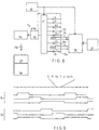
- Fig. 8 shows a more detailed exemplifying embodiment of the system as shown in Fig. 7.
- the system comprises a measurement-sequence unit 43, which controls a multiplexer 41 and a control unit 22 for the heating of the detectors 10 1 and 10 2 , to which control unit the heating power is fed from the unit 21.
- the detector s represents, e.g., the temperature detector of a pressure detector, the detector p a pressure detector, the detector T a temperature detector, and the detectors k 1 and k 2 represent precisely known reference and calibration detectors.
- said detectors which are usually capacitive detectors, are connected to a capacitance part which determines the frequency of the RC oscillator 42, whereby the frequency f M is obtained from the oscillator 42, which frequency is proportional to the quantity to be measured.
- the radio transmitter 36 is modulated with the frequency f M .
- Fig. 9 illustrates the measurement cycles that are repeated one after the other, each of which cycles includes successive readings of the detectors s,p,k 2 , T,u 1 ,u 2 , and k 1 .
- the invention can be combined with a feature by whose means freezing or formation of frost or presence of condensed water on or in the vicinity of the active face of the detector can be detected.
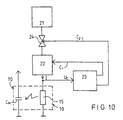
- This feature can be accomplished, e.g., by means of a wiring similar to that shown in Fig. 10, whose operation is characterized by measurement of the rate of heating or equivalent of the heating resistor, for example of the heating resistor 15 present in the constructions as shown in Figs. 4 and 5.
- the wiring shown in Fig. 10 comprises a feed unit 21 for heating power and a unit 23 for detecting the requirement of heating.
- the unit 23 based on the rate of change in the resistance of the heating resistor 15, the requirement of heating is detected on the basis of the input signal U c of the unit 23.
- the unit 23 gives the heating-power regulation unit 22 and/or the unit 24 for regulation of the period of the heating pulse (optional) regulation signals c 1 and c 2 .
- the operation of the unit 23 is based on the fact that, if there is condensed water, frost or ice in connection with the heating resistor 15 and in connection with the detector capacitance C M connected with said resistor 15, after the switching-on of the heating pulse, the rate of increase of the resistance of the heating resistor 15 is substantially slower than in a situation in which there is no condensed water, frost or ice on or near the heating resistor 15 and the active face of the detector capacitance C M , because said water, frost and ice contribute to the formation of a thermal mass that retards the heating of the detector resistor 15.
- the rate of increase of the detector resistance 15 which can be indicated, e.g.
- the heating is discontinued under control by the signals c 1 and/or c 2 of the unit 23.
- the periodic heating of the detector resistance 15 in accordance with the invention is continued under control by the regulation signals c 1 and/or c 2 of the unit 23 until said threshold value is surpassed and/or while following a preset sequence.
Landscapes
- Chemical & Material Sciences (AREA)
- Engineering & Computer Science (AREA)
- Environmental & Geological Engineering (AREA)
- Life Sciences & Earth Sciences (AREA)
- Electrochemistry (AREA)
- Physics & Mathematics (AREA)
- Ecology (AREA)
- Environmental Sciences (AREA)
- Atmospheric Sciences (AREA)
- Chemical Kinetics & Catalysis (AREA)
- Aviation & Aerospace Engineering (AREA)
- Biodiversity & Conservation Biology (AREA)
- Health & Medical Sciences (AREA)
- Analytical Chemistry (AREA)
- Biochemistry (AREA)
- General Health & Medical Sciences (AREA)
- General Physics & Mathematics (AREA)
- Immunology (AREA)
- Pathology (AREA)
- Investigating Or Analyzing Materials By The Use Of Electric Means (AREA)
Applications Claiming Priority (3)
| Application Number | Priority Date | Filing Date | Title |
|---|---|---|---|
| FI933702A FI96640C (fi) | 1993-08-23 | 1993-08-23 | Menetelmä suhteellisen kosteuden mittaamiseksi, etenkin radiosondeissa |
| FI933702 | 1993-08-23 | ||
| EP94850136A EP0640831B1 (de) | 1993-08-23 | 1994-08-15 | Verfahren zur Messung der relativen Feuchtigkeit, insbesondere für Radiosonden |
Related Parent Applications (1)
| Application Number | Title | Priority Date | Filing Date |
|---|---|---|---|
| EP94850136A Division EP0640831B1 (de) | 1993-08-23 | 1994-08-15 | Verfahren zur Messung der relativen Feuchtigkeit, insbesondere für Radiosonden |
Publications (2)
| Publication Number | Publication Date |
|---|---|
| EP0965837A1 true EP0965837A1 (de) | 1999-12-22 |
| EP0965837B1 EP0965837B1 (de) | 2004-11-10 |
Family
ID=8538461
Family Applications (2)
| Application Number | Title | Priority Date | Filing Date |
|---|---|---|---|
| EP94850136A Expired - Lifetime EP0640831B1 (de) | 1993-08-23 | 1994-08-15 | Verfahren zur Messung der relativen Feuchtigkeit, insbesondere für Radiosonden |
| EP99109901A Expired - Lifetime EP0965837B1 (de) | 1993-08-23 | 1994-08-15 | Verfahren und Sensor zur Messung der relativen Feuchtigkeit, insbesondere für Radiosonden |
Family Applications Before (1)
| Application Number | Title | Priority Date | Filing Date |
|---|---|---|---|
| EP94850136A Expired - Lifetime EP0640831B1 (de) | 1993-08-23 | 1994-08-15 | Verfahren zur Messung der relativen Feuchtigkeit, insbesondere für Radiosonden |
Country Status (5)
| Country | Link |
|---|---|
| US (2) | US5485747A (de) |
| EP (2) | EP0640831B1 (de) |
| JP (2) | JP3553657B2 (de) |
| DE (2) | DE69427005T2 (de) |
| FI (1) | FI96640C (de) |
Families Citing this family (33)
| Publication number | Priority date | Publication date | Assignee | Title |
|---|---|---|---|---|
| FI98567C (fi) * | 1993-09-29 | 1997-07-10 | Vaisala Oy | Impedanssianturi, etenkin radiosondikäyttöön, sekä menetelmä anturin valmistamiseksi |
| FI99164C (fi) * | 1994-04-15 | 1997-10-10 | Vaisala Oy | Menetelmä kastepisteen tai kaasupitoisuuden mittaamiseksi sekä laitteisto jäätymisen ennakoimista varten |
| FR2732465B1 (fr) * | 1995-03-31 | 1997-06-06 | Aerospatiale | Procede de mesure du gradient d'humidite dans l'epaisseur d'une piece en materiau composite |
| US5792938A (en) * | 1996-12-13 | 1998-08-11 | Panametrics, Inc. | Humidity sensor with differential thermal detection and method of sensing |
| DE19711371C1 (de) * | 1997-03-19 | 1998-08-27 | Tekmar Elektronik Gmbh & Co | Einrichtung und Verfahren zur Schnee- und Eismeldung |
| FI110287B (fi) * | 1999-06-17 | 2002-12-31 | Vaisala Oyj | Menetelmä ja laitteisto nesteen vesipitoisuuden mittausta varten |
| FI107840B (fi) * | 1999-12-09 | 2001-10-15 | Vaisala Oyj | Mittausmenetelmä ja järjestelmä kosteus- tai kaasuanturia varten |
| US6712504B1 (en) * | 2002-10-01 | 2004-03-30 | Forintek Canada Corp. | Method for determining the relative humidity of a volume of air having a temperature of 100° C or greater |
| DE50206677D1 (de) * | 2002-10-18 | 2006-06-08 | Siemens Schweiz Ag | Verfahren zur Erfassung der Luftfeuchtigkeit mit kapazitivem Feuchte-Messelement |
| DE102004005353B4 (de) | 2004-02-03 | 2016-08-11 | CiS Forschungsinstitut für Mikrosensorik GmbH | Verfahren zur Bestimmung der Parameter von Gasen |
| JP3994975B2 (ja) | 2004-02-27 | 2007-10-24 | 株式会社デンソー | 容量式湿度センサ |
| US7596870B2 (en) * | 2004-03-02 | 2009-10-06 | Leatherman Tool Group, Inc. | Folding multipurpose tool with shears and comfortable handles |
| US7710205B2 (en) * | 2005-11-28 | 2010-05-04 | Seagate Technology Llc | Capacitor detection by phase shift |
| US7456744B2 (en) * | 2006-05-16 | 2008-11-25 | 3M Innovative Properties Company | Systems and methods for remote sensing using inductively coupled transducers |
| FI122007B (fi) * | 2007-02-12 | 2011-07-15 | Vaisala Oyj | Menetelmä ja laite lämpötilariippuvuuksien mittaamiseksi ja menetelmän käyttö mittausvirheiden kompensoimiseen |
| JP5216443B2 (ja) * | 2008-06-30 | 2013-06-19 | アズビル株式会社 | 湿度計測装置 |
| JP5216444B2 (ja) * | 2008-06-30 | 2013-06-19 | アズビル株式会社 | 湿度計測装置 |
| US8230716B2 (en) * | 2009-11-09 | 2012-07-31 | Delphi Technologies, Inc. | Method and system for diagnostics of a particulate matter sensor |
| WO2012141883A1 (en) | 2011-04-13 | 2012-10-18 | 3M Innovative Properties Company | Method of using an absorptive sensor element |
| WO2012141925A1 (en) | 2011-04-13 | 2012-10-18 | 3M Innovative Properties Company | Method of detecting volatile organic compounds |
| KR20140026469A (ko) * | 2011-04-13 | 2014-03-05 | 쓰리엠 이노베이티브 프로퍼티즈 컴파니 | 일체형 가열을 갖는 센서 요소를 포함하는 증기 센서 |
| US9091792B2 (en) * | 2012-08-28 | 2015-07-28 | Foster-Miller, Inc. | Sounding kit |
| US20160003975A1 (en) * | 2013-02-22 | 2016-01-07 | Vaisala Oyj | A radiosonde and a method for atmospheric measurements performed at an elevated temperature |
| US9329160B2 (en) * | 2013-04-05 | 2016-05-03 | Ford Global Technologies, Llc | Humidity sensor diagnostic method using condensation clearing heater |
| DE102013104043A1 (de) * | 2013-04-22 | 2014-10-23 | Epcos Ag | Sensorbauelement und Verfahren zu dessen Herstellung |
| DE102014200060A1 (de) | 2013-08-28 | 2015-03-19 | Micro-Epsilon Messtechnik Gmbh & Co. Kg | Sensorelement und Sensor mit einem entsprechenden Sensorelement |
| CN103438936B (zh) * | 2013-09-02 | 2016-06-15 | 东南大学 | 基于soi片器件层硅阳极键合的电容式温度、湿度和气压传感器集成制造方法 |
| KR101787189B1 (ko) | 2015-06-29 | 2017-11-16 | 한국표준과학연구원 | 복수의 온도센서가 구비된 라디오존데와 이를 이용한 온도 측정 방법 및 그 보정 시스템과 보정 방법 |
| FI127193B (en) * | 2016-12-22 | 2018-01-31 | Vaisala Oyj | Procedure in connection with a radio probe and system |
| DE102017210064A1 (de) * | 2017-06-14 | 2018-12-20 | E + E Elektronik Ges.M.B.H. | Verfahren zum Betrieb einer Sensoranordnung und hierzu geeignete Sensoranordnung |
| LU100589B1 (en) * | 2017-12-22 | 2019-07-25 | Luxembourg Inst Science & Tech List | Directed freezing precipitation detection device and method |
| CN111551593A (zh) * | 2020-04-23 | 2020-08-18 | 西安工程大学 | 一种基于rbf-nn的绝缘子融冰含水率监测方法 |
| EP4417968A1 (de) * | 2023-02-17 | 2024-08-21 | TE Connectivity Sensors France | Feuchtigkeitssensor |
Citations (3)
| Publication number | Priority date | Publication date | Assignee | Title |
|---|---|---|---|---|
| DE3911812A1 (de) * | 1989-04-11 | 1990-10-18 | Siemens Ag | Schneller feuchtesensor auf polymerbasis |
| DE3923595C1 (de) * | 1989-07-17 | 1990-12-20 | Fraunhofer-Gesellschaft Zur Foerderung Der Angewandten Forschung Ev, 8000 Muenchen, De | |
| US5156045A (en) * | 1990-02-21 | 1992-10-20 | Vaisala Oy | Method related to impedance detectors in radiosondes |
Family Cites Families (16)
| Publication number | Priority date | Publication date | Assignee | Title |
|---|---|---|---|---|
| US3075385A (en) * | 1960-12-15 | 1963-01-29 | Clifford M Stover | Hygrometer |
| US3168829A (en) * | 1961-10-05 | 1965-02-09 | Honeywell Inc | Control apparatus |
| US3350941A (en) * | 1965-05-20 | 1967-11-07 | Johnson Service Co | Humidity sensing element |
| DE1598446A1 (de) * | 1966-05-03 | 1969-06-26 | Hoechst Ag | Feuchtigkeitsmessfuehler |
| FI48229C (fi) * | 1972-10-12 | 1974-07-10 | Vaisala Oy | Kapasitiivinen kosteusanturi ja sen valmistumenetelmä. |
| SU597955A1 (ru) * | 1975-06-02 | 1978-03-15 | Институт Экспериментальной Метеорологии | Датчик влажности |
| US4011538A (en) * | 1976-01-30 | 1977-03-08 | Illinois Tool Works Inc. | Fluid sensor |
| FR2498329A1 (fr) * | 1981-01-19 | 1982-07-23 | Commissariat Energie Atomique | Hygrometre capacitif a dielectrique mince et son procede de fabrication |
| JPS58135945A (ja) * | 1982-02-08 | 1983-08-12 | Kakubari Shigeru | 湿度測定素子 |
| DE3313150C1 (de) * | 1983-04-12 | 1984-10-04 | Endress U. Hauser Gmbh U. Co, 7867 Maulburg | Duennschicht-Feuchtsensor zur Messung der absoluten Feuchte und Verfahren zu seiner Herstellung |
| JPH0517650Y2 (de) * | 1986-01-31 | 1993-05-12 | ||
| DE3829517A1 (de) * | 1988-08-31 | 1990-03-08 | Bosch Gmbh Robert | Feuchtesensor |
| DE68928739T2 (de) * | 1988-12-29 | 1999-02-11 | Sharp K.K., Osaka | Detecteur d'humidite |
| US4931897A (en) * | 1989-08-07 | 1990-06-05 | Mitsubishi Denki Kabushiki Kaisha | Method of manufacturing semiconductor capacitive element |
| US5036704A (en) * | 1990-03-23 | 1991-08-06 | Gas Research Institute | Moisture sensor |
| JPH0599877A (ja) * | 1991-06-25 | 1993-04-23 | Yamatake Honeywell Co Ltd | 感湿装置 |
-
1993
- 1993-08-23 FI FI933702A patent/FI96640C/fi active
-
1994
- 1994-08-15 DE DE69427005T patent/DE69427005T2/de not_active Expired - Lifetime
- 1994-08-15 EP EP94850136A patent/EP0640831B1/de not_active Expired - Lifetime
- 1994-08-15 DE DE69434130T patent/DE69434130T2/de not_active Expired - Lifetime
- 1994-08-15 EP EP99109901A patent/EP0965837B1/de not_active Expired - Lifetime
- 1994-08-23 JP JP21955394A patent/JP3553657B2/ja not_active Expired - Fee Related
- 1994-08-23 US US08/294,327 patent/US5485747A/en not_active Expired - Lifetime
-
1995
- 1995-06-06 US US08/467,160 patent/US5511418A/en not_active Expired - Fee Related
-
2003
- 2003-08-13 JP JP2003293195A patent/JP3783114B2/ja not_active Expired - Lifetime
Patent Citations (3)
| Publication number | Priority date | Publication date | Assignee | Title |
|---|---|---|---|---|
| DE3911812A1 (de) * | 1989-04-11 | 1990-10-18 | Siemens Ag | Schneller feuchtesensor auf polymerbasis |
| DE3923595C1 (de) * | 1989-07-17 | 1990-12-20 | Fraunhofer-Gesellschaft Zur Foerderung Der Angewandten Forschung Ev, 8000 Muenchen, De | |
| US5156045A (en) * | 1990-02-21 | 1992-10-20 | Vaisala Oy | Method related to impedance detectors in radiosondes |
Also Published As
| Publication number | Publication date |
|---|---|
| FI933702L (fi) | 1995-02-24 |
| FI933702A0 (fi) | 1993-08-23 |
| US5511418A (en) | 1996-04-30 |
| EP0640831B1 (de) | 2001-04-04 |
| JPH07229973A (ja) | 1995-08-29 |
| DE69427005T2 (de) | 2001-09-13 |
| FI96640B (fi) | 1996-04-15 |
| EP0640831A3 (de) | 1995-05-24 |
| EP0640831A2 (de) | 1995-03-01 |
| DE69434130T2 (de) | 2005-10-13 |
| DE69427005D1 (de) | 2001-05-10 |
| FI96640C (fi) | 1996-07-25 |
| JP3783114B2 (ja) | 2006-06-07 |
| EP0965837B1 (de) | 2004-11-10 |
| JP3553657B2 (ja) | 2004-08-11 |
| US5485747A (en) | 1996-01-23 |
| JP2004069708A (ja) | 2004-03-04 |
| DE69434130D1 (de) | 2004-12-16 |
Similar Documents
| Publication | Publication Date | Title |
|---|---|---|
| US5485747A (en) | Method of measurement of relative humidity, in particular in radiosondes, and humidity detectors that make use of the method | |
| EP0645620B1 (de) | Verfahren und Vorrichtung zur Messung der Feuchtigkeit, insbesondere in Radiosonden | |
| CA1176345A (en) | Temperature control means for a humidity detector | |
| EP0749013B1 (de) | Feuchtigkeitssensor | |
| US5296819A (en) | Polymer capacitative moisture sensitive device comprising heating means | |
| GB2126350A (en) | Dew-point measuring device | |
| EP0353996B1 (de) | Durchflussensor | |
| SE461177B (sv) | Anordning foer maetning av termiska egenskaper hos en provsubstans | |
| JPH1010072A (ja) | 空気の絶対湿度を測定する方法 | |
| JPH0340334B2 (de) | ||
| US4893508A (en) | Humidity sensing apparatus and method therefor | |
| US5156045A (en) | Method related to impedance detectors in radiosondes | |
| US20020036507A1 (en) | Method and arrangement for monitoring surfaces for the presence of dew | |
| KR102499009B1 (ko) | 센서 어셈블리 작동 방법 및 이에 적합한 센서 어셈블리 | |
| FI100739B (fi) | Menetelmä suhteellisen kosteuden mittaamiseksi, etenkin radiosondeissa sekä menetelmää soveltava kosteusanturi | |
| WO2008018425A1 (en) | Liquid surface sensor | |
| JPH0712771A (ja) | ガス検出器 | |
| JPH05323047A (ja) | 降雪量計測装置及びその方法 | |
| JPH0769221B2 (ja) | 温度検知材料、温度センサー及び温度測定方法 | |
| JPH05107099A (ja) | 液面レベル計 | |
| JPH08122163A (ja) | 熱依存性検出装置 | |
| JPH05323045A (ja) | 降雪量計測装置及びその方法 | |
| JPH05323046A (ja) | 降雪量計測装置及びその方法 | |
| CZ281656B6 (cs) | Teplotní čidlo pro měření povrchové i objemové teploty |
Legal Events
| Date | Code | Title | Description |
|---|---|---|---|
| PUAI | Public reference made under article 153(3) epc to a published international application that has entered the european phase |
Free format text: ORIGINAL CODE: 0009012 |
|
| 17P | Request for examination filed |
Effective date: 19990531 |
|
| AC | Divisional application: reference to earlier application |
Ref document number: 640831 Country of ref document: EP |
|
| AK | Designated contracting states |
Kind code of ref document: A1 Designated state(s): CH DE DK ES FR GB IT LI SE |
|
| 17Q | First examination report despatched |
Effective date: 20021105 |
|
| RTI1 | Title (correction) |
Free format text: METHOD AND DETECTOR FOR MEASUREMENT OF RELATIVE HUMIDITY, IN PARTICULAR IN RADIOSONDES |
|
| GRAP | Despatch of communication of intention to grant a patent |
Free format text: ORIGINAL CODE: EPIDOSNIGR1 |
|
| GRAS | Grant fee paid |
Free format text: ORIGINAL CODE: EPIDOSNIGR3 |
|
| GRAA | (expected) grant |
Free format text: ORIGINAL CODE: 0009210 |
|
| AC | Divisional application: reference to earlier application |
Ref document number: 0640831 Country of ref document: EP Kind code of ref document: P |
|
| AK | Designated contracting states |
Kind code of ref document: B1 Designated state(s): CH DE DK ES FR GB IT LI SE |
|
| REG | Reference to a national code |
Ref country code: GB Ref legal event code: FG4D |
|
| REG | Reference to a national code |
Ref country code: CH Ref legal event code: EP |
|
| REF | Corresponds to: |
Ref document number: 69434130 Country of ref document: DE Date of ref document: 20041216 Kind code of ref document: P |
|
| PG25 | Lapsed in a contracting state [announced via postgrant information from national office to epo] |
Ref country code: SE Free format text: LAPSE BECAUSE OF FAILURE TO SUBMIT A TRANSLATION OF THE DESCRIPTION OR TO PAY THE FEE WITHIN THE PRESCRIBED TIME-LIMIT Effective date: 20050210 Ref country code: DK Free format text: LAPSE BECAUSE OF FAILURE TO SUBMIT A TRANSLATION OF THE DESCRIPTION OR TO PAY THE FEE WITHIN THE PRESCRIBED TIME-LIMIT Effective date: 20050210 |
|
| REG | Reference to a national code |
Ref country code: CH Ref legal event code: NV Representative=s name: R. A. EGLI & CO. PATENTANWAELTE |
|
| PG25 | Lapsed in a contracting state [announced via postgrant information from national office to epo] |
Ref country code: ES Free format text: LAPSE BECAUSE OF FAILURE TO SUBMIT A TRANSLATION OF THE DESCRIPTION OR TO PAY THE FEE WITHIN THE PRESCRIBED TIME-LIMIT Effective date: 20050221 |
|
| PLBE | No opposition filed within time limit |
Free format text: ORIGINAL CODE: 0009261 |
|
| STAA | Information on the status of an ep patent application or granted ep patent |
Free format text: STATUS: NO OPPOSITION FILED WITHIN TIME LIMIT |
|
| ET | Fr: translation filed | ||
| 26N | No opposition filed |
Effective date: 20050811 |
|
| PGFP | Annual fee paid to national office [announced via postgrant information from national office to epo] |
Ref country code: IT Payment date: 20080826 Year of fee payment: 15 |
|
| PGFP | Annual fee paid to national office [announced via postgrant information from national office to epo] |
Ref country code: GB Payment date: 20080827 Year of fee payment: 15 |
|
| PGFP | Annual fee paid to national office [announced via postgrant information from national office to epo] |
Ref country code: CH Payment date: 20081121 Year of fee payment: 15 |
|
| REG | Reference to a national code |
Ref country code: CH Ref legal event code: PL |
|
| GBPC | Gb: european patent ceased through non-payment of renewal fee |
Effective date: 20090815 |
|
| PG25 | Lapsed in a contracting state [announced via postgrant information from national office to epo] |
Ref country code: LI Free format text: LAPSE BECAUSE OF NON-PAYMENT OF DUE FEES Effective date: 20090831 Ref country code: CH Free format text: LAPSE BECAUSE OF NON-PAYMENT OF DUE FEES Effective date: 20090831 |
|
| PG25 | Lapsed in a contracting state [announced via postgrant information from national office to epo] |
Ref country code: GB Free format text: LAPSE BECAUSE OF NON-PAYMENT OF DUE FEES Effective date: 20090815 |
|
| PG25 | Lapsed in a contracting state [announced via postgrant information from national office to epo] |
Ref country code: IT Free format text: LAPSE BECAUSE OF NON-PAYMENT OF DUE FEES Effective date: 20090815 |
|
| PGFP | Annual fee paid to national office [announced via postgrant information from national office to epo] |
Ref country code: DE Payment date: 20130821 Year of fee payment: 20 |
|
| PGFP | Annual fee paid to national office [announced via postgrant information from national office to epo] |
Ref country code: FR Payment date: 20130823 Year of fee payment: 20 |
|
| REG | Reference to a national code |
Ref country code: DE Ref legal event code: R071 Ref document number: 69434130 Country of ref document: DE |
|
| PG25 | Lapsed in a contracting state [announced via postgrant information from national office to epo] |
Ref country code: DE Free format text: LAPSE BECAUSE OF EXPIRATION OF PROTECTION Effective date: 20140819 |