EP0965843B1 - Capteur de déplacement - Google Patents
Capteur de déplacement Download PDFInfo
- Publication number
- EP0965843B1 EP0965843B1 EP99111595A EP99111595A EP0965843B1 EP 0965843 B1 EP0965843 B1 EP 0965843B1 EP 99111595 A EP99111595 A EP 99111595A EP 99111595 A EP99111595 A EP 99111595A EP 0965843 B1 EP0965843 B1 EP 0965843B1
- Authority
- EP
- European Patent Office
- Prior art keywords
- diffraction grating
- light
- light beam
- grating
- photodetector
- Prior art date
- Legal status (The legal status is an assumption and is not a legal conclusion. Google has not performed a legal analysis and makes no representation as to the accuracy of the status listed.)
- Expired - Lifetime
Links
- 238000006073 displacement reaction Methods 0.000 title claims description 13
- 238000001514 detection method Methods 0.000 claims description 17
- 230000014509 gene expression Effects 0.000 claims description 13
- 239000000758 substrate Substances 0.000 claims 1
- 230000003287 optical effect Effects 0.000 description 11
- 238000010276 construction Methods 0.000 description 10
- 230000000694 effects Effects 0.000 description 4
- 230000035559 beat frequency Effects 0.000 description 2
- 238000000034 method Methods 0.000 description 2
- 239000012530 fluid Substances 0.000 description 1
- 238000004519 manufacturing process Methods 0.000 description 1
- 238000005259 measurement Methods 0.000 description 1
- 230000010363 phase shift Effects 0.000 description 1
- 230000010287 polarization Effects 0.000 description 1
Images


Classifications
-
- G—PHYSICS
- G01—MEASURING; TESTING
- G01S—RADIO DIRECTION-FINDING; RADIO NAVIGATION; DETERMINING DISTANCE OR VELOCITY BY USE OF RADIO WAVES; LOCATING OR PRESENCE-DETECTING BY USE OF THE REFLECTION OR RERADIATION OF RADIO WAVES; ANALOGOUS ARRANGEMENTS USING OTHER WAVES
- G01S17/00—Systems using the reflection or reradiation of electromagnetic waves other than radio waves, e.g. lidar systems
- G01S17/02—Systems using the reflection of electromagnetic waves other than radio waves
- G01S17/50—Systems of measurement based on relative movement of target
- G01S17/58—Velocity or trajectory determination systems; Sense-of-movement determination systems
-
- G—PHYSICS
- G01—MEASURING; TESTING
- G01D—MEASURING NOT SPECIALLY ADAPTED FOR A SPECIFIC VARIABLE; ARRANGEMENTS FOR MEASURING TWO OR MORE VARIABLES NOT COVERED IN A SINGLE OTHER SUBCLASS; TARIFF METERING APPARATUS; MEASURING OR TESTING NOT OTHERWISE PROVIDED FOR
- G01D5/00—Mechanical means for transferring the output of a sensing member; Means for converting the output of a sensing member to another variable where the form or nature of the sensing member does not constrain the means for converting; Transducers not specially adapted for a specific variable
- G01D5/26—Mechanical means for transferring the output of a sensing member; Means for converting the output of a sensing member to another variable where the form or nature of the sensing member does not constrain the means for converting; Transducers not specially adapted for a specific variable characterised by optical transfer means, i.e. using infrared, visible, or ultraviolet light
- G01D5/32—Mechanical means for transferring the output of a sensing member; Means for converting the output of a sensing member to another variable where the form or nature of the sensing member does not constrain the means for converting; Transducers not specially adapted for a specific variable characterised by optical transfer means, i.e. using infrared, visible, or ultraviolet light with attenuation or whole or partial obturation of beams of light
- G01D5/34—Mechanical means for transferring the output of a sensing member; Means for converting the output of a sensing member to another variable where the form or nature of the sensing member does not constrain the means for converting; Transducers not specially adapted for a specific variable characterised by optical transfer means, i.e. using infrared, visible, or ultraviolet light with attenuation or whole or partial obturation of beams of light the beams of light being detected by photocells
- G01D5/347—Mechanical means for transferring the output of a sensing member; Means for converting the output of a sensing member to another variable where the form or nature of the sensing member does not constrain the means for converting; Transducers not specially adapted for a specific variable characterised by optical transfer means, i.e. using infrared, visible, or ultraviolet light with attenuation or whole or partial obturation of beams of light the beams of light being detected by photocells using displacement encoding scales
- G01D5/34707—Scales; Discs, e.g. fixation, fabrication, compensation
-
- G—PHYSICS
- G01—MEASURING; TESTING
- G01P—MEASURING LINEAR OR ANGULAR SPEED, ACCELERATION, DECELERATION, OR SHOCK; INDICATING PRESENCE, ABSENCE, OR DIRECTION, OF MOVEMENT
- G01P3/00—Measuring linear or angular speed; Measuring differences of linear or angular speeds
- G01P3/36—Devices characterised by the use of optical means, e.g. using infrared, visible, or ultraviolet light
- G01P3/366—Devices characterised by the use of optical means, e.g. using infrared, visible, or ultraviolet light by using diffraction of light
Definitions
- This invention relates to a displacement information measuring apparatus and can be well applied to a velocimeter utilizing the Doppler effect of applying a laser beam, for example, to a moving object or fluid or the like (hereinafter referred to as the "moving object") and detecting the shift of the frequency of scattered light subjected to Doppler shift in conformity with the movement velocity of the moving object to thereby measure the amount of displacement as the information regarding the displacement of the moving object or the movement velocity or the like of the moving object in non-contact.
- a moving object or fluid or the like hereinafter referred to as the "moving object”
- a laser Doppler velocimeter has heretofore been used as an apparatus for measuring the movement velocity of a moving object in non-contact and highly accurately.
- the laser Doppler velocimeter is an apparatus for applying a laser beam to a moving object, and measuring the movement velocity of the moving object by utilizing the effect (Doppler effect) of the frequency of scattered light from the moving object shifting in proportion to the movement velocity of the moving object. moving object.
- Fig. 1A of the accompanying drawings is an illustration showing an example of the laser Doppler velocimeter according to the prior art.
- a laser beam emitted from a laser 1 becomes a parallel light beam 3 by a collimator lens 2, and is divided into two light beams, i.e., transmitted light 5a and reflected light 5b, by a beam splitter 4, and these two light beams are reflected by reflecting mirrors 6a and 6b, whereafter they are applied to a moving object 7 moving at a velocity B at a angle of incident ⁇ from different directions.
- the scattered light from the moving object 7 is detected by a photodetector 9 through a converting lens 8.
- the frequencies of the scattered lights by the two light beams are subjected to the Doppler shifts of + ⁇ f and - ⁇ f in proportion to the movement velocity V.
- the wavelength of the laser beam is ⁇
- the frequency F of the photodetector 9 (hereinafter referred to as the "doppler frequency") is measured from expression (2), the movement velocity V of the moving object 7 will be obtained.
- a method of improving the S/N ratio of a signal in such a velocimeter is proposed, for example, Japanese Patent Application Laid-Open No. 60-243583.
- this publication there is shown a method of condensing a laser beam applied to a moving object in a non-sensitive direction in velocity detection.
- a cylindrical lens is disclosed as means for condensing a laser beam in a non-sensitive direction in velocity detection.
- Fig. 1B of the accompanying drawings shows an example of a laser Doppler velocimeter using an optical system which achieves the downsizing of the entire apparatus.
- a laser beam emitted from a laser 1 becomes a parallel light beam 3 by a collimator lens 2, and enters a diffraction grating G having a grating pitch d.
- Fig. 2 is a perspective view of the essential portions of Embodiment 1 of the present invention
- Fig. 3A shows rays of light as seen along the X-axis of Fig. 2
- Fig. 3B shows rays of light as seen along the Y-axis of Fig. 2.
- This embodiment achieves an improvement in the S/N ratio of a Doppler signal without increasing optical parts, and is characterized in that a diffraction grating is used as deflecting means for making a light enter a moving object at a predetermined angle of incidence ⁇ at a predetermined position and that the shape of the diffraction grating is formed so that the laser beam applied to the moving object may be condensed in a non-sensitive direction in velocity detection.
- gratings of the same hyperbolic shape are formed at the same pitch to thereby optically improve the S/N ratio of a detection signal.
- deflecting means for deflecting a parallel light beam diffraction gratings in which gratings of the same hyperbola are formed at the same pitch in a measurement detecting direction (X direction) are arranged in opposed relationship with each other, whereby it is not necessary to add optical parts and downsizing is realized and yet the S/N ratio of the detection signal is optically improved.
- a laser beam emitted from a laser 1 becomes a parallel light beam 3 by a collimator lens 2 and enters a blazed type diffraction grating (grating portion) G comprising a diffraction grating G1 having diffraction gratings of a hyperbolic shape arranged at a pitch d and a diffraction grating G2 disposed line-symmetrically with the diffraction grating G1 with respect to the Y-axis perpendicularly thereto, and +first-order diffracted light R1 and diffracted light R2 are created by the diffraction gratings G1 and G2, respectively.
- These diffracted lights are kept as parallel light beams in a velocity detecting direction, but emerge so as to be converged at a measuring position in a non-sensitive direction (Y-axis) in velocity detection.
- the diffraction grating G1 and G2 together constitute an element of deflecting means by which a laser beam is incident on a moving object 7 from a predetermined direction.
- Fig. 4 is an illustration showing the diffraction grating shape of the diffraction grating G1 of a hyperbolic shape will now be described.
- Fig. 4 there is shown an example in which the angle of incidence of the laser beam onto the diffraction grating G is perpendicular, by when the angle of incidence of the laser beam changes, the optimum hyperbolic shape changes.
- the hyperbolic shape can be optimally designed so as to condense the laser beam in the non-sensitive direction in velocity detection on the surface to be measured.
- Fig. 5 is a view illustrating the velocity of diffracted light of each order on the object surface 7 to be measured when a parallel light beam is applied to the diffraction grating G.
- +1st-order diffracted light 31 necessary for the detection of the velocity is converged with respect to the non-sensitive direction (Y-axis) in velocity detection, and O-order diffracted light 30 remains being parallel light beam with respect to the direction of the Y-axis, and -1st-order diffracted light 32 becomes divergent with respect to the non-sensitive direction (Y-axis) in velocity detection.
- the diffraction grating is designed such that O-order light is not created, but even when O-order light is created, the density of the light is small correspondingly to the percentage of the width of the light beam to the Y-axis and thus, the percentage of an unnecessary interference component which is a noise component becomes finally negligible.
- Fig. 6 is a perspective view of the essential portions of Embodiment 2 of the present invention.
- a laser beam from a laser 1 is made into a parallel light beam by a collimator lens 2 and enters a first linear diffraction grating G10 of a grating pitch d.
- the incident light is split into two beams by the linear diffraction grating G10.
- Second diffraction gratings G21 and G22 in which hyperbolic shapes are arranged at a grating pitch d/2 have their hyperbolic shapes disposed in opposed relationship with each other and so that the light may be converged on an object surface 7 to be measured in a non-sensitive direction (Y direction) in velocity detection.
- the distance from the second diffraction gratings G21, G22 to the object surface 7 to be measured is defined as WD
- the effect of the present invention can also be obtained by an optical system comprising a combination of a half mirror and a prism.
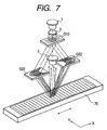
- Fig. 7 is a perspective view of the essential portions of Embodiment 3 of the present invention.
- This embodiment shows a linear encoder.
- the construction in which a light beam from a laser 1 is made into a parallel light beam by a collimator lens 2 and is made to enter an object 7 to be measured by a first diffraction grating G10 and second diffraction gratings G21, G22 is the same as Embodiment 2 of Fig. 6.
- a scale 70 comprising a reflecting type diffraction grating of a grating pitch d is used as the object surface to be measured.
- a photodetector 9 receives scattered light concentrating in a particular direction created by the diffracted lights from the diffraction gratings G21 and G22 entering the reflecting type diffraction grating 70, i.e., the interface light of the diffracted lights.
- the present construction is an optical system for increasing the mounting tolerance, and without a cylindrical lens being disposed, the light beam can be made into a condensed light beam by the scale surface 70, and this construction is excellent in downsizing and assembling property.
- This diffraction grating 70 may be of a transmitting type.
- the photodetector is disposed under the scale 70 of Fig. 7.
- the first diffraction grating G10 may be replaced by a prism type beam splitter. If for example, this beam splitter is made into a polarizing beam splitter having its polarization axis inclined by 45° with respect to the linearly polarized direction of the incident laser beam, and a ⁇ /4 plate and another polarizing beam splitter are disposed in the optical path of the emergent light beam from the scale 70 and each of the light beams split by the another polarizing beam splitter is designed to be received by a photodetector, signals having a phase shift of 90° with each other (so-called two-phase signals) will be obtained from the two photodetectors.
- this beam splitter is made into a polarizing beam splitter having its polarization axis inclined by 45° with respect to the linearly polarized direction of the incident laser beam, and a ⁇ /4 plate and another polarizing beam splitter are disposed in the optical path of the emergent light beam from the scale 70 and each of the light beams split
- the hyperbolic shape is formed at the same pitch, as the shape of the diffraction grating for condensing the laser beam in the non-sensitive direction (Y direction) in velocity detection, but the central portion of the Y-axis of the hyperbolic shape substantially coincides with a circular shape and therefor, when the effective beam diameter is sufficiently small, the hyperbolic shape approximately includes an arcuate shape.
- a diffraction grating is used as deflection means for making light enter a moving object, and the shape of the diffraction grating is formed so that the light beam applied to the moving object may be condensed in a non-sensitive direction in velocity detection, whereby without increasing optical parts such as a cylindrical lens, etc., there can be achieved a displacement information measuring apparatus which can obtain a signal of good S/N and can obtain highly accurate displacement information by a simple construction.
Landscapes
- Physics & Mathematics (AREA)
- Electromagnetism (AREA)
- Engineering & Computer Science (AREA)
- General Physics & Mathematics (AREA)
- Computer Networks & Wireless Communication (AREA)
- Radar, Positioning & Navigation (AREA)
- Remote Sensing (AREA)
- Power Engineering (AREA)
- Length Measuring Devices By Optical Means (AREA)
- Optical Transform (AREA)
Claims (8)
- Appareil pour détecter une information de déplacement d'un objet comprenant :dans lequel ledit moyen de déviation comprend un réseau de diffraction destiné à diffracter le faisceau lumineux devant être incident sur ledit objet, ledit réseau de diffraction étant formé de façon que le faisceau lumineux appliqué audit objet puisse être condensé sur ledit objet dans une direction dans laquelle le déplacement relatif dudit objet ne peut pas être détecté par le signal provenant dudit photodétecteur.une unité à source de lumière ;un moyen de déviation destiné à dévier un faisceau lumineux provenant de ladite unité à source de lumière afin que le faisceau lumineux dévié par ledit moyen de déviation soit incident sur ledit objet ; etun photodétecteur destiné à détecter la lumière provenant dudit objet lors de l'incidence sur celui-ci du faisceau lumineux provoquée par ledit moyen de déviation, une information concernant le déplacement relatif dudit objet le long d'une direction prédéterminée étant détectée sur la base d'un signal de détection de lumière provenant dudit photodétecteur ;
- Appareil selon la revendication 1, dans lequel ledit réseau de diffraction (G, G1, G2, G21, G22) est formé de façon que des réseaux de la même forme hyperbolique soient agencés à un pas donné dans ladite direction prédéterminée (X).
- Appareil selon la revendication 2, dans lequel ledit réseau de diffraction (G) comporte deux rangées de réseau (G1, G2, G21, G22) dans lesquelles des réseaux de la même forme hyperbolique agencés à un pas donné dans ladite direction prédéterminée (X) sont disposés dans des sens opposés.
- Appareil selon la revendication 3, dans lequel lesdites deux rangées de réseau (G1, G2) sont formées sur le même substrat.
- Appareil selon la revendication 3, comprenant en outre un réseau (G10) de diffraction de division destiné à diviser le faisceau lumineux provenant de ladite unité à source de lumière (1), certaines, respectives, desdites deux rangées de réseau (G21, G22) étant disposées de façon à dévier ceux, correspondants, des deux faisceaux lumineux divisés par ledit réseau (G10) de diffraction de division.
- Appareil selon la revendication 2, dans lequel le faisceau lumineux devant être incident sur ledit réseau de diffraction (G, G1, G2, G21, G22) est formé en un faisceau lumineux parallèle et, lorsque ladite direction prédéterminée est la direction de l'axe X et la direction dans laquelle le déplacement relatif dudit objet (7, 70) ne peut pas être détecté par le signal provenant dudit photodétecteur (9), est la direction de l'axe Y, et la distance allant dudit réseau de diffraction (G, G1, G2, G21, G22) jusqu'audit objet (7, 70) est définie comme WD et l'angle de diffraction dans ladite direction de l'axe X par ledit réseau de diffraction (G, G1, G2, G21, G22) est défini comme , l'hyperbole desdites rangées de réseau est représentée par l'expression suivante :
- Appareil selon la revendication 1, dans lequel ledit objet (70) est une échelle ayant un réseau de diffraction.
- Appareil selon la revendication 1, dans lequel ledit réseau de diffraction (G) est un réseau de diffraction du type échelette.
Applications Claiming Priority (2)
| Application Number | Priority Date | Filing Date | Title |
|---|---|---|---|
| JP18567998 | 1998-06-16 | ||
| JP18567998A JP3937596B2 (ja) | 1998-06-16 | 1998-06-16 | 変位情報測定装置 |
Publications (2)
| Publication Number | Publication Date |
|---|---|
| EP0965843A1 EP0965843A1 (fr) | 1999-12-22 |
| EP0965843B1 true EP0965843B1 (fr) | 2004-05-19 |
Family
ID=16174981
Family Applications (1)
| Application Number | Title | Priority Date | Filing Date |
|---|---|---|---|
| EP99111595A Expired - Lifetime EP0965843B1 (fr) | 1998-06-16 | 1999-06-15 | Capteur de déplacement |
Country Status (4)
| Country | Link |
|---|---|
| US (1) | US6259531B1 (fr) |
| EP (1) | EP0965843B1 (fr) |
| JP (1) | JP3937596B2 (fr) |
| DE (1) | DE69917374T2 (fr) |
Families Citing this family (8)
| Publication number | Priority date | Publication date | Assignee | Title |
|---|---|---|---|---|
| EP1028309B1 (fr) * | 1999-02-04 | 2003-04-16 | Dr. Johannes Heidenhain GmbH | Codeur optique |
| US7012691B2 (en) * | 2002-08-06 | 2006-03-14 | Sharp Kabushiki Kaisha | Optical moving information measuring apparatus and carrier system incorporating the same |
| US7295315B2 (en) * | 2003-06-30 | 2007-11-13 | Kenneth C. Johnson | Focus and alignment sensors and methods for use with scanning microlens-array printer |
| JP4789511B2 (ja) * | 2004-06-04 | 2011-10-12 | キヤノン株式会社 | 状況モニタリング装置及び状況モニタリングシステム |
| KR101184167B1 (ko) | 2006-09-08 | 2012-09-18 | 지에스아이 그룹 코포레이션 | 광 위치 인코더 |
| DE102014211004A1 (de) * | 2014-06-10 | 2015-12-17 | Dr. Johannes Heidenhain Gmbh | Optische Positionsmesseinrichtung |
| CN111174680B (zh) * | 2020-02-10 | 2021-08-03 | 覃高杰 | 一种传感器及传感器多点变形同步检测方法 |
| KR20220152679A (ko) * | 2021-05-10 | 2022-11-17 | 엘지이노텍 주식회사 | 거리 측정 카메라 모듈 |
Family Cites Families (10)
| Publication number | Priority date | Publication date | Assignee | Title |
|---|---|---|---|---|
| JPS60243583A (ja) * | 1984-05-18 | 1985-12-03 | Canon Inc | レ−ザドツプラ速度計 |
| JPS62154623A (ja) * | 1985-12-27 | 1987-07-09 | Hitachi Ltd | 半導体露光装置 |
| JPH01232214A (ja) | 1988-03-11 | 1989-09-18 | Canon Inc | エンコーダ |
| US5066130A (en) | 1988-05-10 | 1991-11-19 | Canon Kabushiki Kaisha | Displacement measuring apparatus |
| JP2649390B2 (ja) | 1988-10-12 | 1997-09-03 | キヤノン株式会社 | 信号内挿回路 |
| US5021649A (en) | 1989-03-28 | 1991-06-04 | Canon Kabushiki Kaisha | Relief diffraction grating encoder |
| JP2962819B2 (ja) | 1990-11-30 | 1999-10-12 | キヤノン株式会社 | 変位測定装置 |
| US5204516A (en) * | 1991-04-23 | 1993-04-20 | U.S. Philips Corporation | Planar optical scanning head having deficiency-correcting grating |
| BE1007513A3 (nl) * | 1993-09-13 | 1995-07-18 | Philips Electronics Nv | Meetinrichting voor het bepalen van de verplaatsing van een beweegbaar voorwerp. |
| JP3028716B2 (ja) * | 1993-09-29 | 2000-04-04 | キヤノン株式会社 | 光学式変位センサ |
-
1998
- 1998-06-16 JP JP18567998A patent/JP3937596B2/ja not_active Expired - Fee Related
-
1999
- 1999-06-15 US US09/333,043 patent/US6259531B1/en not_active Expired - Lifetime
- 1999-06-15 DE DE69917374T patent/DE69917374T2/de not_active Expired - Lifetime
- 1999-06-15 EP EP99111595A patent/EP0965843B1/fr not_active Expired - Lifetime
Also Published As
| Publication number | Publication date |
|---|---|
| EP0965843A1 (fr) | 1999-12-22 |
| DE69917374T2 (de) | 2005-03-17 |
| DE69917374D1 (de) | 2004-06-24 |
| JP2000002510A (ja) | 2000-01-07 |
| JP3937596B2 (ja) | 2007-06-27 |
| US6259531B1 (en) | 2001-07-10 |
Similar Documents
| Publication | Publication Date | Title |
|---|---|---|
| EP0645608B1 (fr) | Capteur optique de déplacement | |
| JP5046780B2 (ja) | 光エンコーダ | |
| US5036192A (en) | Rotary encoder using reflected light | |
| US7061624B2 (en) | Grating interference type optical encoder | |
| EP0651232B2 (fr) | Codeur rotatif | |
| US6771377B2 (en) | Optical displacement sensing device with reduced sensitivity to misalignment | |
| US5481106A (en) | Encoder with an optical scale and interference of zero and first order diffraction beams | |
| EP0390092B2 (fr) | Codeur | |
| EP0397202B1 (fr) | Codeur | |
| US20030160966A1 (en) | Displacement measuring device with interference grating | |
| US6259531B1 (en) | Displacement information measuring apparatus with hyperbolic diffraction grating | |
| US5737070A (en) | Displacement information measuring apparatus | |
| EP1347271B1 (fr) | Dispositif optique de détection de déplacement avec une sensibilité réduite à un défaut d'alignement | |
| JPH07306060A (ja) | エンコーダ | |
| JP2005147828A (ja) | 変位検出装置 | |
| JP3218657B2 (ja) | ロータリーエンコーダ | |
| EP0672891B2 (fr) | Capteur optique de déplacement | |
| JPH02262064A (ja) | レーザードップラー速度計 | |
| CN223741493U (zh) | 光栅位移测量装置 | |
| JP3501529B2 (ja) | 光学式変位測定装置 | |
| JP3142217B2 (ja) | 回転センサ | |
| JPH03115809A (ja) | エンコーダ | |
| JPH1130667A (ja) | 変位情報検出装置 | |
| JPS62163921A (ja) | ロ−タリ−エンコ−ダ− | |
| JPS62200223A (ja) | エンコ−ダ− |
Legal Events
| Date | Code | Title | Description |
|---|---|---|---|
| PUAI | Public reference made under article 153(3) epc to a published international application that has entered the european phase |
Free format text: ORIGINAL CODE: 0009012 |
|
| AK | Designated contracting states |
Kind code of ref document: A1 Designated state(s): DE GB NL |
|
| AX | Request for extension of the european patent |
Free format text: AL;LT;LV;MK;RO;SI |
|
| 17P | Request for examination filed |
Effective date: 20000508 |
|
| AKX | Designation fees paid |
Free format text: DE GB NL |
|
| GRAP | Despatch of communication of intention to grant a patent |
Free format text: ORIGINAL CODE: EPIDOSNIGR1 |
|
| GRAS | Grant fee paid |
Free format text: ORIGINAL CODE: EPIDOSNIGR3 |
|
| GRAA | (expected) grant |
Free format text: ORIGINAL CODE: 0009210 |
|
| AK | Designated contracting states |
Kind code of ref document: B1 Designated state(s): DE GB NL |
|
| REG | Reference to a national code |
Ref country code: GB Ref legal event code: FG4D |
|
| REF | Corresponds to: |
Ref document number: 69917374 Country of ref document: DE Date of ref document: 20040624 Kind code of ref document: P |
|
| PLBE | No opposition filed within time limit |
Free format text: ORIGINAL CODE: 0009261 |
|
| STAA | Information on the status of an ep patent application or granted ep patent |
Free format text: STATUS: NO OPPOSITION FILED WITHIN TIME LIMIT |
|
| 26N | No opposition filed |
Effective date: 20050222 |
|
| PGFP | Annual fee paid to national office [announced via postgrant information from national office to epo] |
Ref country code: GB Payment date: 20150626 Year of fee payment: 17 Ref country code: DE Payment date: 20150630 Year of fee payment: 17 |
|
| PGFP | Annual fee paid to national office [announced via postgrant information from national office to epo] |
Ref country code: NL Payment date: 20150511 Year of fee payment: 17 |
|
| REG | Reference to a national code |
Ref country code: DE Ref legal event code: R119 Ref document number: 69917374 Country of ref document: DE |
|
| REG | Reference to a national code |
Ref country code: NL Ref legal event code: MM Effective date: 20160701 |
|
| GBPC | Gb: european patent ceased through non-payment of renewal fee |
Effective date: 20160615 |
|
| PG25 | Lapsed in a contracting state [announced via postgrant information from national office to epo] |
Ref country code: DE Free format text: LAPSE BECAUSE OF NON-PAYMENT OF DUE FEES Effective date: 20170103 |
|
| PG25 | Lapsed in a contracting state [announced via postgrant information from national office to epo] |
Ref country code: GB Free format text: LAPSE BECAUSE OF NON-PAYMENT OF DUE FEES Effective date: 20160615 Ref country code: NL Free format text: LAPSE BECAUSE OF NON-PAYMENT OF DUE FEES Effective date: 20160701 |