EP0965901B1 - Multifunktioneller Joystick zur Kontrolle eines landwirtschaftlichen Fahrzeuges - Google Patents
Multifunktioneller Joystick zur Kontrolle eines landwirtschaftlichen Fahrzeuges Download PDFInfo
- Publication number
- EP0965901B1 EP0965901B1 EP99201742A EP99201742A EP0965901B1 EP 0965901 B1 EP0965901 B1 EP 0965901B1 EP 99201742 A EP99201742 A EP 99201742A EP 99201742 A EP99201742 A EP 99201742A EP 0965901 B1 EP0965901 B1 EP 0965901B1
- Authority
- EP
- European Patent Office
- Prior art keywords
- control
- thumb
- switch
- operator
- self
- Prior art date
- Legal status (The legal status is an assumption and is not a legal conclusion. Google has not performed a legal analysis and makes no representation as to the accuracy of the status listed.)
- Expired - Lifetime
Links
- 210000003813 thumb Anatomy 0.000 claims description 56
- 210000003811 finger Anatomy 0.000 claims description 23
- 238000003306 harvesting Methods 0.000 claims description 13
- 230000033001 locomotion Effects 0.000 claims description 13
- 230000003213 activating effect Effects 0.000 claims 1
- 235000013339 cereals Nutrition 0.000 description 25
- 210000004935 right thumb Anatomy 0.000 description 10
- 241001124569 Lycaenidae Species 0.000 description 5
- 230000007935 neutral effect Effects 0.000 description 5
- 210000000707 wrist Anatomy 0.000 description 5
- 230000006872 improvement Effects 0.000 description 4
- 238000000926 separation method Methods 0.000 description 3
- 230000004913 activation Effects 0.000 description 2
- 210000005224 forefinger Anatomy 0.000 description 2
- 230000007246 mechanism Effects 0.000 description 2
- 239000010813 municipal solid waste Substances 0.000 description 2
- 241000209140 Triticum Species 0.000 description 1
- 235000021307 Triticum Nutrition 0.000 description 1
- 235000009754 Vitis X bourquina Nutrition 0.000 description 1
- 235000012333 Vitis X labruscana Nutrition 0.000 description 1
- 240000006365 Vitis vinifera Species 0.000 description 1
- 235000014787 Vitis vinifera Nutrition 0.000 description 1
- 230000036626 alertness Effects 0.000 description 1
- 230000005540 biological transmission Effects 0.000 description 1
- 230000008859 change Effects 0.000 description 1
- 238000004140 cleaning Methods 0.000 description 1
- 230000000994 depressogenic effect Effects 0.000 description 1
- 239000004459 forage Substances 0.000 description 1
- 239000011521 glass Substances 0.000 description 1
- 230000002706 hydrostatic effect Effects 0.000 description 1
- 230000002028 premature Effects 0.000 description 1
- 230000000284 resting effect Effects 0.000 description 1
- 230000000007 visual effect Effects 0.000 description 1
Images


Classifications
-
- G—PHYSICS
- G05—CONTROLLING; REGULATING
- G05G—CONTROL DEVICES OR SYSTEMS INSOFAR AS CHARACTERISED BY MECHANICAL FEATURES ONLY
- G05G1/00—Controlling members, e.g. knobs or handles; Assemblies or arrangements thereof; Indicating position of controlling members
- G05G1/58—Rests or guides for relevant parts of the operator's body
-
- G—PHYSICS
- G05—CONTROLLING; REGULATING
- G05G—CONTROL DEVICES OR SYSTEMS INSOFAR AS CHARACTERISED BY MECHANICAL FEATURES ONLY
- G05G1/00—Controlling members, e.g. knobs or handles; Assemblies or arrangements thereof; Indicating position of controlling members
- G05G1/01—Arrangements of two or more controlling members with respect to one another
Definitions
- This invention relates to the improvement of an agricultural combine. More specifically it relates to an improvement of the multifunctional handle for controlling an agricultural combine.
- a combine harvester generally includes a header which cuts the crop.
- the header then moves the cut crop into a feeder house.
- the feeder house lifts the cut crop into the threshing and separation areas of the combine.
- the grain is separated from the stalk by a rotor or threshing system.
- the grain is then moved and stored in a grain tank.
- the chaff and trash are deposited from the rear of the combine.
- the grain stored in the grain tank is eventually discharged through a grain tank unload tube.
- An operator usually runs these various operations from a glass-enclosed cab. Typically, the cab is located above and behind the header.
- the operator sits in a chair within the cab of harvester.
- a control console positioned to the right side of the operator.
- the operator's right hand controls a variety of the harvester's systems.
- the combine harvester During harvesting periods it is not uncommon for the combine harvester to be operated for an extended time. Sometimes a single operator will use a combine for 16 to 18 hours a day. Furthermore, several operators may alternate in the use of the combine. Therefore it is necessary to provide a control system which will allow maximum operator comfort and flexibility. This will permit the operator to remain mentally alert for the long time intervals needed to harvest crops.
- One aspect of maintaining the operator's alertness is to provide a multifunctional handle for controlling the harvester that is comfortable and has the controls placed in a manner to allow for easy use.
- the controls on the handle should be placed in such a manner to eliminate the need for the operator to be constantly looking away from the field and into the cab to view instrumentation. Ideally, the controls should be able to be reached by easy movements and by touch of either the fingers or thumb.
- combine harvesters use a single control stick with the great bulk of the controls positioned on the control console. The operator is constantly looking away from the field to manipulate these controls. This can become distracting and decrease the productivity of the operator.
- US-A-4,574,651 discloses a control stick unit. This unit has a multitude of switches. Unfortunately, it would make it difficult for an operator to be able to re-position their finger or thumb correctly after moving to activate a switch. It is possible that operator could inadvertently re-position over the incorrect switch. Depending on the particular switch, this could have disastrous consequences.
- US-A-4,738,417 illustrates a hand operated control.
- the handle in this patent is more ergonometrically pleasing, however it only controls one switch.
- US-A-4,862,165 illustrates an controller or computer 'mouse'. This device has several curved surface and a few switches. Because of the limited number of switches, it is easy for a user to avoid getting confused while using the switches.
- US-A-5,042,314 discloses a steering and transmission shifting control mechanism.
- the control mechanism uses a single switch which is controlled by the operator's thumb. However, it could be difficult for the operator to distinguish between the various settings on the joystick. This could result in an inappropriate setting or the need for the operator to constantly view the joystick to check the settings.
- US-A-5,340,067 discloses a hand and wrist support for computer mouse. This represents another improvement to a computer mouse design for a computer system. Again, the controls are very limited. In this design there only appears to be one switch.
- US-A-5,503,040 discusses a computer interface device. The device holds the operator's fingers in position over several switches. Unfortunately this could become uncomfortable after an extended interval.
- US-A-5,577,417 illustrates a tactile and/or kinaesthetic manual information return control member. This device uses pressure on control member to control the various systems.
- US-A-5,566,586 describes as closest prior art a multifunctional handle for a utility vehicle having an upright palm grip and a control region having control switches on top of the grip.
- the operator may manipulate the switches using his thumb while the palm of his hand keeps resting against the grip.
- the wrist remains in a vertical position.
- the handle is pushed forwards or pulled rearwards, the angular position the grip changes and implies a torque on the still vertical wrist. This induces stress in the wrist and causes premature fatigue.
- a self-propelled agricultural machine including a control console and a multifunctional handle having a first side and a second side said handler comprising:
- the palm grip and the finger rest provide a natural and comfortable rest position for the hand.
- the controls are easy to reach by arc movement of the thumb.
- a most ergonomical position is realized when the palm grip and finger rest descend in a tapered fashion from the crescent control area. Preferably this taper is in the range of 30 to 45 degrees from the horizontal.
- the crescent may be provided with stepped control surfaces to allow easy locating of the various switches. Such embodiment facilitates the use of multiple operator controls within a small area. The steps provide an excellent tactile feel.
- the handle further may have a thumb rest area positioned between these control areas.
- the rest area can be provided with a thumb ledge, assisting in positioning of the thumb.
- the rest area may have a curvature or a dimple, providing the multifunctional handle with a fixed point of reference from which to operate the controls.
- the handle may have a middle control area with a plurality of control switches between the upper and lower control areas.
- the central switch may have a dimple, equally constituting a point of reference for the operator's thumb.
- a switch such as a mechanical neutral trigger switch, may be installed on the finger rest. The operator thus uses controls on the front and back sides on the handle.
- Operation of the controls is facilitated by arranging the switches in order of use, starting from the central control area or the thumb rest area.
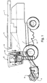
- Figure 1 illustrates a typical combine 1 having a pair of front wheels (only one shown) and a pair of rear wheels (only one shown) for providing movement over the ground.
- a header 3 for cutting a crop.
- the header has a reel 4 which moves the grain into an auger trough.
- a transverse auger pushes the grain and stalk in the auger trough to the center of the header.
- the header illustrated in Figure 1 is a wheat or similar small grain header. It may be positioned and re-positioned relative to the ground. The header may also be tilted to the left or right or may be positioned relatively high or low to the ground.
- the header reel 4 may also be positioned relative to the header 3. The position and rotation speed of the header reel 4 again depend on the terrain and crop conditions. Moveable headers and header reels are well known and established in the art.
- the feeder Located at the center of the header is the feeder or elevator.
- the feeder moves the grain and stalks rearward into the threshing, separation and cleaning systems 6 of the combine.
- the processed grain is stored in a grain tank 5 located near the top of the combine.
- the grain is removed from the grain tank 5 by an unloading auger (not shown) through the grain tank unload tube 7. Usually during harvesting operations, the unloading auger remains off and the grain tank unload tube 7 remains positioned aside the grain tank 5.
- the combine can be unloaded 'on the go'.
- the combine 1 is followed by a separate vehicle such as a truck or tractor-pulled grain cart.
- the processed grain is discharged while the combine and separate vehicle are moving.
- the operator 14 activates the unload tube 7.
- the operator 14 positions the end of the unload tube 7 over a receptacle.
- Unloading augers and unload auger grain tubes are well known and established in the art.
- the trash or chaff is ejected from the rear of the combine.
- the operator 14 controls the combine 1 from the cab 2 located behind and above the header 3 and at the front of the combine. From the cab the operator can observe most of the various combine functions.
- the cab 2 usually has a large glass window or several windows which afford the operator 14 the maximum ability to monitor the header 3.
- the present invention comprises a multifunctional handle 20 for controlling an agricultural combine.
- the handle 20 is positioned within the cab 2.
- the multifunction handle 20 also contains several switches and controls which may be manipulated by the operator 14 without requiring that the operator 14 constantly be looking down at the control console 8 or at the multifunctional handle 20. If the operator must constantly be reviewing the controls, then he is prevented from vigilantly observing the crop and terrain conditions.
- a multifunctional handle 20, containing the critical switches, that is designed in a manner so the operator is capable of knowing the position of his thumb and fingers relative to the controls without visual cues would represent a great improvement in the art.
- the present multifunctional handle 20 accomplishes this by means of a crescent control region 40 positioned proximal to an ergonomically advantageously designed palm grip 30 and finger rest 35. Spaced on the crescent control region 40 are several controls and switches which can be manipulated by the operator's right thumb 11 rotating either clockwise 70 or counter-clock wise 71.
- the multifunctional handle 20 comprises the crescent control region 40.
- the crescent control region has two control areas 41, 53 and a thumb rest area 46.
- the upper control area 41 has three switches. There is the unload tube switch 42.
- the unload tube switch 42 engages the unload auger within the unload tube 7.
- This switch 42 is electrically linked to the controller for this unloading system in a conventional manner.
- an unload tube switch guard means protecting the unload tube switch 42.
- the unload tube switch guard means consists of a unload tube switch ridge 43.
- Another embodiment of the switch guard means, as seen in Figure 7, consists of a unload tube switch bevelled region 43A.
- This region 43A surrounds the unload tube switch 42 and necessitates the operator's right thumb 12 to carefully contact the switch 42 while avoiding contact with the bevelled region 43A. It is necessary to add the switch guard means to protect the unload tube switch 42 from inadvertent activation. Improper activation of this switch 42 could result in crop being discharged at the wrong moment from the grain tank, e.g. when the tube 7 is not positioned over the bin of the truck or the cart.
- the upper control area 41 also has an unload tube movement control switch 44.
- the movement control switch 44 controls the motion of the unload tube 7 away and towards the combine 1.
- the switch 44 is electrically linked in a conventional manner to the controller of unload tube 7.
- This switch 45A moves the header upwards, downwards, tilts it left and tilts it right.
- the header control switch 45A is electrically linked in a conventional manner to the controller on the header control system.
- the unload tube switch 42 is positioned highest and furthest away from the middle of the crescent control region 40.
- the four-way header control switch 45A is usually being constantly manipulated by the operator 14 so it is positioned closer to the middle of the crescent control region 40.
- the upper step 45 Separating the upper control area 41 from the thumb rest area 46 is the upper step 45. This step is a slight rise from the upper control area 41 to the thumb rest area 46.
- the upper step 45 is 'stepped' sufficiently to allow the operator's right thumb 11 to tactilely sense the difference between the upper control area 41 and thumb rest area 46.
- the thumb rest area 46 has a curvature 46A and a thumb ledge 47. These features help the operator orient his right thumb 11 by tactilely sensing the thumb's position.
- the curvature 46A and thumb ledge 47 also provide for a comfortable base position for the right thumb 11 to rest between tasks.
- the lower step 61 Between the thumb rest area 46 and lower control area 53 is the lower step 61. Similar to the upper step 45, the lower step 61 has a slight depression from the lower control area 53 and thumb rest area 46. Again the lower step 61 is 'stepped' sufficiently to allow the operator's right thumb 11 to tactilely sense that the thumb has left the thumb rest area 46 and has moved into the lower control area 53.
- the lower control area 53 has three switches: a header resume switch 54, a reel control four-way switch 55 and a reel speed switch 60.
- the header resume switch 54 is used to raise the header 3 out of the crop and when depressed again will lower the header back to the position the header was in when it left the crop. The operator 14 can then quickly lower the header 3 after a turn is made and the combine 1 is ready to resume harvesting operations.
- the header resume switch 51 is electrically linked to a header controller in a conventional manner.
- the reel control four-way switch 55 adjusts the position of the reel 4 relative to the header 3.
- the switch 55 moves the reel up, down, forward and rearwards relative the header 3.
- the reel control four-way switch 55 is electrically linked to the reel controller in a conventional manner.
- the reel speed switch 60 adjusts the rotational speed of the header reel 4. Again, the reel speed switch 60 is electrically linked to the reel speed controller in a conventional manner.
- the lower control area switches 54, 55, 56 are positioned in order of their usage.
- the reel speed control switch 60 is used the least so it is positioned farthest from the middle of the crescent control region 40.
- the header resume switch 54 is used the most so it is the closest to the middle of the crescent control region 40.
- the thumb rest area 46 is replaced with a middle control area 48 and the four-way header control switch 45A in the upper control area 41 is removed.
- the functions of the four-way header control switch 45A are provided by three switches in the middle control area 48.
- the three switches consist of the header raise/lower switch 49, the header lateral float - counter-clockwise motion switch 50 and the header lateral float - clockwise motion switch 51. These three switches 49-51 are electrically linked to the header control system in a conventional manner.
- a dimple 52 In the center of the header raise/lower switch 49 is a dimple 52. The dimple is designed to be tactilely sensed by the operator's right thumb 11.
- the middle control area 48 is slanted sideways and has a side edge which extends at a lower level than the surrounding upper control area 41, lower control area 53 and palm grip 30. This arrangement improves the awareness of the position of the operator's thumb even further.
- the palm grip 30 Affixed to the crescent control region is the palm grip 30.
- the finger rest 35 At the top of the palm grip 30 and extending to the rear side 22 of the multifunctional handle 20 is the finger rest 35.
- the palm grip 30 and finger rest 35 gradually taper 31 from the horizon in a range from 30 to 45 degrees. This allows the operator to maintain the position of his wrist 10 and right hand 9 at a natural, ergonomically comfortable position.
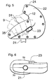
- a neutral trigger 23 On the rear side 22 near the base of the finger rest 35 is a neutral trigger 23, as shown in Figure 5.
- the neutral trigger 23 is controlled by the operator's right fore finger 12.
- the neutral trigger is a conventional mechanical switch which the operator activates when it is desired to move the combine from forward motion to reverse motion.
- Also seen in Figure 5, on the rear side 22 of the handle 20 are a series of attachment bolts 24 for holding the rear side 22 to the remainder of the handle 20.
- the palm grip 30 is connected by the control console 8 by a support tube 21.
- the operator 14 will have his right hand 9 with the palm on the palm grip 30.
- the operator's right fingers will lay over the finger rest 35.
- the entire handle 20 can be moved (arrows 72 in Figure 2) to the relative control console 8 by the operator pushing the palm grip 30 or pulling the finger rest 35.
- the operator's right fore finger 12 engages the neutral trigger 23 if it is desired to change the direction of the combine 1.
- the operator's right thumb 11 remains on the thumb rest area 46 in the curvature 46A or on the thumb ledge 47 in the crescent control region 40.
- the operator rotates his right thumb 11 clockwise (arrow 70 in Figure 4) to engage those switches.
- the operator needs to engage switches on the lower control area 53 he rotates his thumb 11 counter-clockwise (arrow 71).
- mirror image control handle may be developed for left-hand control of the combine. Similar handles may also be used in other self-propelled agricultural machines such as forage harvesters, grape harvesters, mower-conditioners, etc.
Landscapes
- Physics & Mathematics (AREA)
- General Physics & Mathematics (AREA)
- Engineering & Computer Science (AREA)
- Automation & Control Theory (AREA)
- Harvester Elements (AREA)
Claims (18)
- Selbstfahrende landwirtschaftliche Maschine (1), die eine Steuerkonsole (8) und einen Multifunktions-Handgriff (20) umfasst, der eine erste Seite und eine zweite Seite (22) aufweist, wobei der Handgriff Folgendes umfasst:einen Handflächen-Griff (30) zur Aufnahme der Handfläche einer Hand (9) des Fahrers;ein Halterohr (21), das den Handflächen-Griff (30) mit der Steuerkonsole (8) verbindet;eine Fingerauflage (35), die an dem Handflächen-Griff (30) angebracht ist, um die Finger der Hand (9) aufzunehmen; undeinen Steuerbereich (40), der an dem Handflächen-Griff (30) angebracht ist, und eine Anzahl von Steuerschaltern (42, 44, 45A, 54, 55, 60, 49-51) zur Steuerung der landwirtschaftlichen Maschine (1) umfasst, wobei ein Daumen (11) der Hand (9) die Anzahl von Steuerschaltern auf dem Steuerbereich (10) betätigen kann, während die Handfläche gegen den Handflächen-Griff (30) ruht,dadurch gekennzeichnet, dass
sich die Fingerauflage (35) von der Oberseite des Handflächen-Griffes (30) zu der zweiten Seite (22) des Handgriffes (20) erstreckt; und
der Steuerbereich ein sichelförmiger Steuerbereich (40) ist, sich auf der ersten Seite des Handflächen-Griffes (30) befindet und einen oberen Steuerbereich (41), der sich höher als die Oberseite des Handflächen-Griffes (30) erstreckt, und einen unteren Steuerbereich (53) umfasst, der sich tiefer als die Oberseite erstreckt, wobei die Steuerbereiche (41, 53) jeweils eine Anzahl von Steuerschaltern (42, 44, 45A/54, 55, 60) umfassen,
wobei die Anzahl von Steuerschaltern (42, 44, 45A) auf dem oberen Steuerbereich (41) durch den Daumen (11) des Fahrers steuerbar ist, nachdem der Daumen nach oben gedreht wurde, während die Handfläche auf dem Handflächen-Griff (30) ruht, und
die Anzahl von Steuerschaltern (54, 55, 60) auf dem unteren Steuerbereich (53) durch den Daumen des Fahrers steuerbar ist, nachdem der Daumen nach unten gedreht wurde, während die Handfläche auf dem Handflächen-Griff (30) ruht. - Selbstfahrende landwirtschaftliche Maschine nach Anspruch 1, dadurch gekennzeichnet, dass der sichelförmige Steuerbereich (40) abgestuft ist, wodurch der Fahrer die Anzahl von Steuerschaltern (42, 44, 45A, 54, 55, 60, 49-51) unterscheiden kann.
- Selbstfahrende landwirtschaftliche Maschine nach Anspruch 1 oder 2, dadurch gekennzeichnet, dass:das Halterohr (21) gegenüber der Steuerkonsole (8) bewegt werden kann; unddie Fingerauflage (35) einen mechanischen Auslöseschalter (23) zur Ermöglichung einer Bewegung des Halterohres (21) über einen mechanischen Anschlag hinaus umfasst.
- Selbstfahrende landwirtschaftliche Maschine nach einem der vorhergehenden Ansprüche, dadurch gekennzeichnet, dass sich der Handflächen-Griff (30) und die Fingerauflage (35) in einer sich verjüngenden Weise von dem sichelförmigen Steuerbereich aus nach unten erstrecken, dass die Verjüngung (31) im Bereich von 30 bis 45 Grad von einer horizontalen Linie von dem sichelförmigen Steuerbereich (40) liegt, wodurch die Handfläche und die Finger (12) des Fahrers in einer ergonometrischen Position angeordnet sind.
- Selbstfahrende landwirtschaftliche Maschine nach einem der vorhergehenden Ansprüche, dadurch gekennzeichnet, dass der sichelförmige Steuerbereich (40) einen Daumen-Auflagebereich (46) umfasst, der zwischen dem oberen Steuerbereich (41) und dem unteren Steuerbereich (53) angeordnet ist.
- Selbstfahrende landwirtschaftliche Maschine nach Anspruch 5 unter Rückbeziehung auf Anspruch 2, dadurch gekennzeichnet, dass sich der obere Steuerbereich (41) in einer niedrigeren Höhenlage als der Daumen-Auflagebereich (46) befindet, so dass der Daumen (11) des Fahrers den oberen Steuerbereich (41) von der Daumen-Auflagefläche (46) unterscheiden kann.
- Selbstfahrende landwirtschaftliche Maschine nach Anspruch 5 unter Rückbeziehung auf Anspruch 2, dadurch gekennzeichnet, dass der untere Steuerbereich (51) niedriger als der Daumen-Auflagebereich (46) angeordnet ist, so dass der Daumen (11) des Fahrers den unteren Steuerbereich (53) von dem Daumen-Auflagebereich (46) unterscheiden kann.
- Selbstfahrende landwirtschaftliche Maschine nach einem der Ansprüche 5 bis 7, dadurch gekennzeichnet, dass der Daumen-Auflagebereich (46) weiterhin eine Daumen-Leiste (47) umfasst, wodurch der Daumen (11) angeordnet werden kann und die Positionierung des Daumens (11) unterstützt wird.
- Selbstfahrende landwirtschaftliche Maschine nach einem der Ansprüche 5 bis 8, dadurch gekennzeichnet, dass der Daumen-Auflagebereich (46) eine Krümmung (46A) aufweist, so dass der Daumen (11) des Fahrers in dem Daumen-Auflagebereich (46) angeordnet werden kann.
- Selbstfahrende landwirtschaftliche Maschine nach einem der Ansprüche 1 bis 4, dadurch gekennzeichnet, dass der sichelförmige Steuerbereich (40) weiterhin einen mittleren Steuerbereich (48) umfasst, der zwischen dem oberen Steuerbereich (41) und dem unteren Steuerbereich (53) angeordnet ist, wobei der mittlere Steuerbereich eine Anzahl von Steuerschaltern (49-51) aufweist.
- Selbstfahrende landwirtschaftliche Maschine nach Anspruch 10, dadurch gekennzeichnet, dass der mittlere Steuerbereich (48) seitlich geneigt ist und eine Seitenkante aufweist, die sich an einer niedrigeren Höhenlage als der obere Steuerbereich (41) und der untere Steuerbereich (53) erstreckt wodurch der Daumen (11) des Fahrers den mittleren Steuerbereich (48) von den oberen und unteren Steuerbereichen unterscheiden kann.
- Selbstfahrende landwirtschaftliche Maschine nach Anspruch 10 oder 11, dadurch gekennzeichnet, dass der mittlere Steuerbereich (48) einen Schalter (49) umfasst, der eine Vertiefung (52) aufweist, so dass der Fahrer seinen Daumen (11) positionieren kann.
- Selbstfahrende landwirtschaftliche Maschine nach einem der vorhergehenden Ansprüche, dadurch gekennzeichnet, dass:die Anzahl von Steuerschaltern zumindest einen Ein/Aus-Schalter (42) einschließt; undder sichelförmige Steuerbereich (40) weiterhin eine Schalter-Schutzeinrichtung (43/43A) proximal zu dem Ein/Aus-Schalter (42) aufweist, so dass verhindert wird, dass der Daumen (11) des Fahrers unbeabsichtigt mit dem Ein/Aus-Schalter in Kontakt kommt.
- Selbstfahrende landwirtschaftliche Maschine nach Anspruch 13, dadurch gekennzeichnet, dass die Schalter-Schutzeinrichtung eine Schalter-Schutzrippe (43) umfasst, die zwischen dem Ein/Aus-Schalter (42) und einem anderen Schalter (44) der Anzahl von Schaltern angeordnet ist.
- Selbstfahrende landwirtschaftliche Maschine nach Anspruch 13, dadurch gekennzeichnet, dass die Schalter-Schutzeinrichtung einen erhöhten abgeschrägten Bereich (43A) aufweist, der den Ein/Aus-Schalter (42) umgibt.
- Selbstfahrende landwirtschaftliche Erntemaschine nach einem der vorhergehenden Ansprüche, dadurch gekennzeichnet, dass die Anzahl der Schalter in dem oberen Steuerbereich (43) Folgendes umfasst:einen Zweiweg-Kippschalter (44) zur Steuerung der Bewegung eines Entladerohres (7) auf der landwirtschaftlichen Erntemaschine (1);einen Ein/Aus-Schalter (42) zum Aktivieren des Entladerohres (7).
- Selbstfahrende landwirtschaftliche Erntemaschine nach einem der vorhergehenden Ansprüche, dadurch gekennzeichnet, dass die Anzahl von Schaltern in dem unteren Steuerbereich (53) Folgendes umfasst:einen Vorsatzgeräte-Wiederaufnahme-Schalter (54) zur Wiederaufnahme der Position eines Vorsatzgerätes (3) der landwirtschaftlichen Erntemaschine (1); undeinen Vierweg-Kippschalter (55) zur Positionssteuerung einer Haspel (4) auf dem Vorsatzgerät (3); undeinen Zweiweg-Kippschalter (60) zur Drehgeschwindigkeits-Steuerung der Haspel (4).
- Selbstfahrende landwirtschaftliche Erntemaschine nach einem der Ansprüche 10 bis 12, dadurch gekennzeichnet, dass der mittlere Steuerbereich (48) einen Zweiweg-Kippschalter (49) zum Anheben/Absenken eines Vorsatzgerätes (3) der landwirtschaftlichen Erntemaschine (1), einen Steuerschalter (50) für die Neigung des Vorsatzgerätes im Gegenuhrzeigersinn und einen Steuerschalter (51) für eine Neigung des Vorsatzgerätes im Uhrzeigersinn aufweist.
Applications Claiming Priority (2)
| Application Number | Priority Date | Filing Date | Title |
|---|---|---|---|
| US8965298P | 1998-06-17 | 1998-06-17 | |
| US89652P | 1998-06-17 |
Publications (3)
| Publication Number | Publication Date |
|---|---|
| EP0965901A2 EP0965901A2 (de) | 1999-12-22 |
| EP0965901A3 EP0965901A3 (de) | 2004-01-14 |
| EP0965901B1 true EP0965901B1 (de) | 2007-10-10 |
Family
ID=22218846
Family Applications (1)
| Application Number | Title | Priority Date | Filing Date |
|---|---|---|---|
| EP99201742A Expired - Lifetime EP0965901B1 (de) | 1998-06-17 | 1999-06-02 | Multifunktioneller Joystick zur Kontrolle eines landwirtschaftlichen Fahrzeuges |
Country Status (3)
| Country | Link |
|---|---|
| US (1) | US6148593A (de) |
| EP (1) | EP0965901B1 (de) |
| DE (1) | DE69937270T2 (de) |
Families Citing this family (35)
| Publication number | Priority date | Publication date | Assignee | Title |
|---|---|---|---|---|
| ATE387651T1 (de) * | 2001-03-29 | 2008-03-15 | Komatsu Utility Europe Spa | Steuerhebel für erdbewegungsmaschinen |
| US20020157498A1 (en) * | 2001-04-26 | 2002-10-31 | Black Phillip John | Split grip control lever for heavy machinery |
| US6612636B2 (en) * | 2001-08-29 | 2003-09-02 | Deere & Company | Hand reference for control panel of utility vehicle |
| US6928350B2 (en) | 2001-10-29 | 2005-08-09 | Visteon Global Technologies, Inc. | Control console for an automobile |
| US6568161B1 (en) | 2001-11-15 | 2003-05-27 | New Holland North America, Inc. | User interface for a harvesting machine |
| GB2402727A (en) * | 2003-06-14 | 2004-12-15 | Cnh Uk Ltd | Lockable joystick control with wrist support |
| US6871483B1 (en) | 2004-06-10 | 2005-03-29 | Cnh America Llc | Header height resume |
| US20060016634A1 (en) * | 2004-07-22 | 2006-01-26 | Cnh America Llc | Handle-style loading control panel for bale wagons |
| EP1650642B1 (de) * | 2004-10-20 | 2016-06-22 | Harman Becker Automotive Systems GmbH | On-board elektronisches System für ein Fahrzeug, Fahrzeug-Multimediasystem und Verfahren zur Konfigurierung von on-board elektronisches System für ein Fahrzeug |
| US7407439B1 (en) | 2004-12-29 | 2008-08-05 | Ochoa Justin J | Apparatus and system for reconfigurable two-hand game controllers |
| CA2505431C (en) | 2005-03-22 | 2011-10-11 | Macdon Industries Ltd. | Swather with automatic reel control |
| DE102005017013B4 (de) * | 2005-04-07 | 2009-02-26 | Kässbohrer Geländefahrzeug AG | Steuergriff für eine Handsteuereinheit |
| DE102005019321A1 (de) * | 2005-04-26 | 2006-11-02 | Still Gmbh | Flurförderzeug mit einem Multifunktionshebel |
| US7275616B2 (en) * | 2005-06-30 | 2007-10-02 | Cnh America Llc | Adjustable combination propulsion and control handle for a work machine |
| US7511236B2 (en) | 2006-12-01 | 2009-03-31 | Kaessbohrer Gelaendefahrzeug Ag | Manual control unit for a vehicle |
| US7729835B2 (en) * | 2007-08-21 | 2010-06-01 | Jcb Compact Products Limited | Method of controlling a working machine |
| US8276476B2 (en) * | 2007-10-03 | 2012-10-02 | Caterpillar Inc. | Joystick offset controls |
| WO2009050745A1 (en) * | 2007-10-17 | 2009-04-23 | Komatsu Utility Europe S.P.A. | Control device for earth moving machines |
| GB2460658A (en) | 2008-06-04 | 2009-12-09 | Valtra Oy Ab | Driver interface for a utility vehicle |
| US8186136B2 (en) * | 2009-04-03 | 2012-05-29 | Deere & Company | Agricultural harvester with a draper platform direction shuttle |
| US20130074645A1 (en) * | 2009-12-17 | 2013-03-28 | Jon Håkansson | Control lever for operating a working machine |
| US9567065B2 (en) | 2010-10-07 | 2017-02-14 | Bae Systems Plc | Vehicle armrest |
| DE102012002992A1 (de) * | 2012-02-15 | 2013-08-22 | Claas Selbstfahrende Erntemaschinen Gmbh | Landwirtschaftliches Arbeitsfahrzeug |
| DE202012006899U1 (de) * | 2012-07-17 | 2013-10-18 | Alois Pöttinger Maschinenfabrik Ges.m.b.H. | Landwirtschaftliche Maschine |
| JP6317202B2 (ja) | 2014-07-08 | 2018-04-25 | 株式会社クボタ | 多機能操作具及びアームレスト操作装置 |
| US10036139B2 (en) * | 2014-11-24 | 2018-07-31 | Caterpillar Inc. | Machine input device having multi-axis tool control |
| USD771152S1 (en) | 2015-09-02 | 2016-11-08 | The Charles Machine Works, Inc. | Joystick |
| WO2017141420A1 (ja) * | 2016-02-19 | 2017-08-24 | 株式会社小松製作所 | 作業車両の操作装置 |
| JP6657423B2 (ja) * | 2016-04-07 | 2020-03-04 | ジェイエルジー インダストリーズ インク.Jlg Industries Inc. | 産業ビークル用の制御ボックス兼操作者インターフェース |
| DE102017109849A1 (de) | 2017-05-08 | 2018-11-08 | Claas Selbstfahrende Erntemaschinen Gmbh | Verfahren zur Abarbeitung eines landwirtschaftlichen Ernteprozesses |
| US10591948B1 (en) * | 2018-08-30 | 2020-03-17 | Essex Industries, Inc. | Collective control system for a rotorcraft |
| EP3760025B1 (de) * | 2019-07-01 | 2025-12-17 | Andreas Stihl AG & Co. KG | Bedienvorrichtung mit handgriff und motorgetriebenes arbeitsgerät |
| US11614766B2 (en) | 2020-04-09 | 2023-03-28 | Caterpillar Inc. | Machine joystick with comfort and accessibility features |
| US11573591B2 (en) | 2020-04-10 | 2023-02-07 | Caterpillar Inc. | Machine joystick with ergonomic features |
| US12269542B2 (en) * | 2023-06-23 | 2025-04-08 | The Toro Company | Compact utility vehicle |
Family Cites Families (30)
| Publication number | Priority date | Publication date | Assignee | Title |
|---|---|---|---|---|
| US4012014A (en) * | 1975-09-11 | 1977-03-15 | Mcdonnell Douglas Corporation | Aircraft flight controller |
| CA1132026A (en) * | 1979-08-13 | 1982-09-21 | Versatile Cornat Corporation | Rotary combine |
| DE3042731A1 (de) | 1979-11-14 | 1981-05-27 | Sperry N.V., Zedelgem | Maehdrescher |
| SE436154B (sv) * | 1980-01-24 | 1984-11-12 | Olsbergs Hydraulic Ab | Anordning for att styra medietillforseln till ett antal forbrukare |
| US4332261A (en) * | 1980-09-24 | 1982-06-01 | Sperry Corporation | Automatic hydraulic neutralizing mechanism |
| SE431433B (sv) * | 1982-06-01 | 1984-02-06 | Saab Scania Ab | Spakenhet med flera funktioner |
| US4522553A (en) * | 1982-09-13 | 1985-06-11 | Deere & Company | Combine power boost system |
| US4641857A (en) * | 1985-06-28 | 1987-02-10 | Gailiunas Ernest A | Ski pole hand grip |
| DE3674404D1 (de) * | 1986-06-24 | 1990-10-25 | Ford New Holland Inc | Schneidtisch fuer erntemaschine. |
| EP0250654B1 (de) * | 1986-07-01 | 1990-09-05 | Ford New Holland N.V. | Mähdrescher |
| US4738417A (en) * | 1987-02-02 | 1988-04-19 | Fmc Corporation | Hand operated control |
| US4866920A (en) * | 1987-06-29 | 1989-09-19 | Deere & Company | Unloading auger position switch |
| AU595973B2 (en) * | 1988-01-20 | 1990-04-12 | Genhone Lai | An improved structure of racket handles |
| US4862165A (en) * | 1988-02-12 | 1989-08-29 | Samuel Gart | Ergonomically-shaped hand controller |
| US4967544A (en) * | 1989-01-05 | 1990-11-06 | Deere & Company | Automatic speed control system for a harvesting assembly |
| US5042314A (en) * | 1989-11-02 | 1991-08-27 | Caterpillar Inc. | Steering and transmission shifting control mechanism |
| US5155984A (en) * | 1991-04-24 | 1992-10-20 | Ford New Holland, Inc. | Implement height control |
| US5332322A (en) * | 1991-06-06 | 1994-07-26 | Gambaro Thomas L | Ergonomic thumb-actuable keyboard for a hand-grippable device |
| DE4204223A1 (de) * | 1992-02-13 | 1993-08-19 | Zahnradfabrik Friedrichshafen | Steuerknueppel zum schalten bzw. betaetigen von bauelementen eines nutzkraftfahrzeugs |
| US5340067A (en) * | 1992-03-27 | 1994-08-23 | Martin Teresa A | Hand and wrist support for computer mouse |
| FR2712406B1 (fr) * | 1993-11-08 | 1995-12-15 | Commissariat Energie Atomique | Organe de commande manuelle à retour d'information tactile et/ou kinesthésique. |
| US5503040A (en) * | 1993-11-12 | 1996-04-02 | Binagraphics, Inc. | Computer interface device |
| DE4341834C1 (de) * | 1993-12-08 | 1995-04-20 | Claas Ohg | Landmaschine, insbesondere Mähdrescher, mit Multiprozessor-Leitvorrichtung |
| US5472156A (en) * | 1994-03-28 | 1995-12-05 | The United States Of America As Represented By The Secretary Of The Army | Air combat collective control head |
| DE4431824C1 (de) * | 1994-09-07 | 1996-05-02 | Claas Ohg | Mähdrescherbetrieb mit Betriebsdatenkataster |
| DE9417838U1 (de) * | 1994-11-08 | 1994-12-22 | Jungheinrich Ag, 22047 Hamburg | Handbetätigte Stellvorrichtung für einen Bedienungsstand bzw. -sitz |
| EP0850555B1 (de) * | 1995-09-11 | 2006-02-22 | YANMAR AGRICULTURAL EQUIPMENT Co., Ltd. | Ansteuervorrichtung für arbeitsfahrzeug |
| KR100371456B1 (ko) * | 1995-10-09 | 2004-03-30 | 닌텐도가부시키가이샤 | 삼차원화상처리시스템 |
| US5768947A (en) * | 1996-06-24 | 1998-06-23 | Caterpillar Inc. | Implement hand support and control |
| US6061617A (en) * | 1997-10-21 | 2000-05-09 | Case Corporation | Adaptable controller for work vehicle attachments |
-
1999
- 1999-04-12 US US09/289,872 patent/US6148593A/en not_active Expired - Lifetime
- 1999-06-02 EP EP99201742A patent/EP0965901B1/de not_active Expired - Lifetime
- 1999-06-02 DE DE69937270T patent/DE69937270T2/de not_active Expired - Lifetime
Also Published As
| Publication number | Publication date |
|---|---|
| DE69937270D1 (de) | 2007-11-22 |
| EP0965901A2 (de) | 1999-12-22 |
| DE69937270T2 (de) | 2008-01-17 |
| EP0965901A3 (de) | 2004-01-14 |
| US6148593A (en) | 2000-11-21 |
Similar Documents
| Publication | Publication Date | Title |
|---|---|---|
| EP0965901B1 (de) | Multifunktioneller Joystick zur Kontrolle eines landwirtschaftlichen Fahrzeuges | |
| US6932183B2 (en) | Control apparatus for an agricultural machine | |
| US6871483B1 (en) | Header height resume | |
| US20140053093A1 (en) | Electronic control and display unit | |
| JP7805494B2 (ja) | 自動走行方法 | |
| JP6882997B2 (ja) | 収穫機 | |
| JP7620458B2 (ja) | 自動運転方法、作業車両及び自動運転システム | |
| US20190166759A1 (en) | Unloading conveyor swing control system | |
| JP2001245524A (ja) | 汎用コンバイン | |
| JPH1066437A (ja) | 移動農機の操作装置 | |
| JP2004089150A (ja) | 作業車両の操作スイッチ配置構造 | |
| JP2865100B2 (ja) | コンバインの操縦装置 | |
| JP3445351B2 (ja) | コンバインにおける刈取前処理装置の昇降制御装置 | |
| JP2002051629A (ja) | 作業機械の制御装置 | |
| JP3316673B2 (ja) | コンバイン | |
| JPH10155342A (ja) | コンバイン | |
| KR20230155426A (ko) | 작업 기계용의 조작 장치, 및 작업 기계 | |
| JP7178943B2 (ja) | コンバイン | |
| JP2021052631A (ja) | コンバイン | |
| JPH0759441A (ja) | コンバインの刈取装置 | |
| JP2001251923A (ja) | コンバインにおける刈取前処理装置の昇降制御装置 | |
| JP2025080957A (ja) | 収穫機 | |
| JPH119064A (ja) | 作業機の操縦手段 | |
| JP2024178591A (ja) | コンバインおよびコンバインの制御方法 | |
| KR20120085460A (ko) | 콤바인의 예취부 원터치 상승장치 |
Legal Events
| Date | Code | Title | Description |
|---|---|---|---|
| PUAI | Public reference made under article 153(3) epc to a published international application that has entered the european phase |
Free format text: ORIGINAL CODE: 0009012 |
|
| AK | Designated contracting states |
Kind code of ref document: A2 Designated state(s): AT BE CH CY DE DK ES FI FR GB GR IE IT LI LU MC NL PT SE |
|
| AX | Request for extension of the european patent |
Free format text: AL;LT;LV;MK;RO;SI |
|
| RAP1 | Party data changed (applicant data changed or rights of an application transferred) |
Owner name: CNH BELGIUM N.V. |
|
| PUAL | Search report despatched |
Free format text: ORIGINAL CODE: 0009013 |
|
| AK | Designated contracting states |
Kind code of ref document: A3 Designated state(s): AT BE CH CY DE DK ES FI FR GB GR IE IT LI LU MC NL PT SE |
|
| AX | Request for extension of the european patent |
Extension state: AL LT LV MK RO SI |
|
| RIC1 | Information provided on ipc code assigned before grant |
Ipc: 7G 05G 1/10 B Ipc: 7G 05G 1/26 B Ipc: 7G 05G 9/047 A |
|
| 17P | Request for examination filed |
Effective date: 20040708 |
|
| AKX | Designation fees paid |
Designated state(s): DE DK FR GB IT |
|
| GRAP | Despatch of communication of intention to grant a patent |
Free format text: ORIGINAL CODE: EPIDOSNIGR1 |
|
| GRAS | Grant fee paid |
Free format text: ORIGINAL CODE: EPIDOSNIGR3 |
|
| GRAA | (expected) grant |
Free format text: ORIGINAL CODE: 0009210 |
|
| AK | Designated contracting states |
Kind code of ref document: B1 Designated state(s): DE DK FR GB IT |
|
| REG | Reference to a national code |
Ref country code: GB Ref legal event code: FG4D |
|
| REF | Corresponds to: |
Ref document number: 69937270 Country of ref document: DE Date of ref document: 20071122 Kind code of ref document: P |
|
| ET | Fr: translation filed | ||
| PG25 | Lapsed in a contracting state [announced via postgrant information from national office to epo] |
Ref country code: DK Free format text: LAPSE BECAUSE OF FAILURE TO SUBMIT A TRANSLATION OF THE DESCRIPTION OR TO PAY THE FEE WITHIN THE PRESCRIBED TIME-LIMIT Effective date: 20071010 |
|
| PLBE | No opposition filed within time limit |
Free format text: ORIGINAL CODE: 0009261 |
|
| STAA | Information on the status of an ep patent application or granted ep patent |
Free format text: STATUS: NO OPPOSITION FILED WITHIN TIME LIMIT |
|
| 26N | No opposition filed |
Effective date: 20080711 |
|
| PGFP | Annual fee paid to national office [announced via postgrant information from national office to epo] |
Ref country code: IT Payment date: 20090619 Year of fee payment: 11 |
|
| PG25 | Lapsed in a contracting state [announced via postgrant information from national office to epo] |
Ref country code: IT Free format text: LAPSE BECAUSE OF NON-PAYMENT OF DUE FEES Effective date: 20100602 |
|
| REG | Reference to a national code |
Ref country code: DE Ref legal event code: R082 Ref document number: 69937270 Country of ref document: DE Representative=s name: PATENTANWAELTE WALLACH, KOCH & PARTNER, DE |
|
| REG | Reference to a national code |
Ref country code: DE Ref legal event code: R082 Ref document number: 69937270 Country of ref document: DE Representative=s name: PATENTANWAELTE WALLACH, KOCH, DR. HAIBACH, FEL, DE Effective date: 20140428 Ref country code: DE Ref legal event code: R082 Ref document number: 69937270 Country of ref document: DE Representative=s name: PATENTANWAELTE WALLACH, KOCH & PARTNER, DE Effective date: 20140428 Ref country code: DE Ref legal event code: R081 Ref document number: 69937270 Country of ref document: DE Owner name: CNH INDUSTRIAL BELGIUM NV, BE Free format text: FORMER OWNER: CNH BELGIUM NV, ZEDELGEM, BE Effective date: 20140428 |
|
| REG | Reference to a national code |
Ref country code: FR Ref legal event code: CD Owner name: CNH INDUSTRIAL BELGIUM NV Effective date: 20140725 |
|
| REG | Reference to a national code |
Ref country code: FR Ref legal event code: PLFP Year of fee payment: 17 |
|
| REG | Reference to a national code |
Ref country code: DE Ref legal event code: R084 Ref document number: 69937270 Country of ref document: DE |
|
| REG | Reference to a national code |
Ref country code: GB Ref legal event code: 746 Effective date: 20150421 |
|
| REG | Reference to a national code |
Ref country code: DE Ref legal event code: R084 Ref document number: 69937270 Country of ref document: DE Effective date: 20150414 |
|
| PGFP | Annual fee paid to national office [announced via postgrant information from national office to epo] |
Ref country code: GB Payment date: 20150416 Year of fee payment: 17 Ref country code: DE Payment date: 20150416 Year of fee payment: 17 |
|
| PGFP | Annual fee paid to national office [announced via postgrant information from national office to epo] |
Ref country code: FR Payment date: 20150413 Year of fee payment: 17 |
|
| REG | Reference to a national code |
Ref country code: DE Ref legal event code: R119 Ref document number: 69937270 Country of ref document: DE |
|
| GBPC | Gb: european patent ceased through non-payment of renewal fee |
Effective date: 20160602 |
|
| REG | Reference to a national code |
Ref country code: FR Ref legal event code: ST Effective date: 20170228 |
|
| PG25 | Lapsed in a contracting state [announced via postgrant information from national office to epo] |
Ref country code: FR Free format text: LAPSE BECAUSE OF NON-PAYMENT OF DUE FEES Effective date: 20160630 Ref country code: DE Free format text: LAPSE BECAUSE OF NON-PAYMENT OF DUE FEES Effective date: 20170103 |
|
| PG25 | Lapsed in a contracting state [announced via postgrant information from national office to epo] |
Ref country code: GB Free format text: LAPSE BECAUSE OF NON-PAYMENT OF DUE FEES Effective date: 20160602 |