EP0966094A2 - Fonctionnement réduit d'un moteur a induction à enroulment multiple en cas de pan d'onduleur - Google Patents
Fonctionnement réduit d'un moteur a induction à enroulment multiple en cas de pan d'onduleur Download PDFInfo
- Publication number
- EP0966094A2 EP0966094A2 EP99111072A EP99111072A EP0966094A2 EP 0966094 A2 EP0966094 A2 EP 0966094A2 EP 99111072 A EP99111072 A EP 99111072A EP 99111072 A EP99111072 A EP 99111072A EP 0966094 A2 EP0966094 A2 EP 0966094A2
- Authority
- EP
- European Patent Office
- Prior art keywords
- inverters
- current
- torque
- providing
- failed
- Prior art date
- Legal status (The legal status is an assumption and is not a legal conclusion. Google has not performed a legal analysis and makes no representation as to the accuracy of the status listed.)
- Granted
Links
Images






Classifications
-
- H—ELECTRICITY
- H02—GENERATION; CONVERSION OR DISTRIBUTION OF ELECTRIC POWER
- H02P—CONTROL OR REGULATION OF ELECTRIC MOTORS, ELECTRIC GENERATORS OR DYNAMO-ELECTRIC CONVERTERS; CONTROLLING TRANSFORMERS, REACTORS OR CHOKE COILS
- H02P25/00—Arrangements or methods for the control of AC motors characterised by the kind of AC motor or by structural details
- H02P25/16—Arrangements or methods for the control of AC motors characterised by the kind of AC motor or by structural details characterised by the circuit arrangement or by the kind of wiring
- H02P25/22—Multiple windings; Windings for more than three phases
-
- H—ELECTRICITY
- H02—GENERATION; CONVERSION OR DISTRIBUTION OF ELECTRIC POWER
- H02P—CONTROL OR REGULATION OF ELECTRIC MOTORS, ELECTRIC GENERATORS OR DYNAMO-ELECTRIC CONVERTERS; CONTROLLING TRANSFORMERS, REACTORS OR CHOKE COILS
- H02P21/00—Arrangements or methods for the control of electric machines by vector control, e.g. by control of field orientation
- H02P21/22—Current control, e.g. using a current control loop
-
- H—ELECTRICITY
- H02—GENERATION; CONVERSION OR DISTRIBUTION OF ELECTRIC POWER
- H02P—CONTROL OR REGULATION OF ELECTRIC MOTORS, ELECTRIC GENERATORS OR DYNAMO-ELECTRIC CONVERTERS; CONTROLLING TRANSFORMERS, REACTORS OR CHOKE COILS
- H02P21/00—Arrangements or methods for the control of electric machines by vector control, e.g. by control of field orientation
- H02P21/06—Rotor flux based control involving the use of rotor position or rotor speed sensors
- H02P21/08—Indirect field-oriented control; Rotor flux feed-forward control
- H02P21/09—Field phase angle calculation based on rotor voltage equation by adding slip frequency and speed proportional frequency
-
- H—ELECTRICITY
- H02—GENERATION; CONVERSION OR DISTRIBUTION OF ELECTRIC POWER
- H02P—CONTROL OR REGULATION OF ELECTRIC MOTORS, ELECTRIC GENERATORS OR DYNAMO-ELECTRIC CONVERTERS; CONTROLLING TRANSFORMERS, REACTORS OR CHOKE COILS
- H02P23/00—Arrangements or methods for the control of AC motors characterised by a control method other than vector control
- H02P23/08—Controlling based on slip frequency, e.g. adding slip frequency and speed proportional frequency
Definitions
- This invention relates to improving the curtailed operation of a multiple-wound induction motor which is driven by a corresponding plurality of pulse width modulated (PWM) inverters, following failure of one or more inverters.
- PWM pulse width modulated
- each inverter corresponding to a winding set on the motor. It is also known to allow functioning inverters to operate the motor following failure of one or more of the inverters. In such a case, each inverter drives the winding set to which it corresponds, and the failed inverters are cut off from the system. It is possible to use a tandem motor configuration so that the functioning inverters can operate the motor without switching. However, tandem configurations are costly and require excessively long shaft length. For a double wound tandem configuration, the shaft is twice as long as a single wound motor.
- HEI 7[1995]-002037 causes the current command to be reduced by one-half to operate a three-phase double wound motor following the failure of one inverter.
- the excitation current command, I O *, and torque current command, I T * within the motor become one-half of what they would be with both inverters driving the motor, so that motor torque is reduced to one-quarter of normal torque.
- Objects of the invention include provision of a three-phase multiple wound motor with plural inverter units which will provide torque greater than the torque which the motor would produce as a normal response to the individual inverter units which remain functioning following failure of one or more other inverter units; and providing, during curtailed operation of a multiple-wound three-phase motor following a failure of one or more inverters, motor torque which is higher than that provided during curtailed operation following inverter failure in three-phase multiple-wound motor systems known to the prior art.
- an elevator motor drive system comprising a multiple-wound, three-phase, variable speed motor having a plurality, N, of winding sets, a plurality, N, of pulse width modulation inverters each for providing current to a corresponding one of said winding sets, an actual speed detector responsive to the angular motion of said motor to provide an actual speed signal, a speed controller receiving an angular speed command signal and providing a torque current command signal as a limited function of the difference between said angular command signal and said actual speed signal, means providing an excitation current command signal, a first arithmetic function for providing a torque current command limit equal to the share root of the difference between the square of the summation of maximum current which can be tolerated by all of said inverters collectively and the square of said excitation current command, characterized by comprising a failure control for providing switch control output signals in response to a failure in any of said inverters, and for disconnecting from said motor any inverter sensed to have failed, a failure control for providing switch control output signals in
- the excitation current and the torque current of the functioning inverters is changed from being 1/N to being 1 /(N-M), where N is the total number of inverters and M is the number of failed inverters, so that the required current is supplied with fewer inverters.
- the excitation current command provided to the functioning inverters is a proportional fraction of the maximum current which each inverter may supply.
- failure of one out of a plurality of inverters driving a multiple-wound, three-phase motor interrupts the current feedback loop of the functioning inverters, so that the motor is overdriven in an open-ended fashion, relying only on the speed feedback loop.
- the torque current provided by functioning inverters to a multiple-wound, three-phase motor, after one more inverters have failed is controlled by limiting the speed command to that which results in an acceleration achievable within the maximum torque capable of being provided by the functioning inverters, taking into account their current limits.
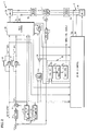
- a three-phase, double-wound variable speed motor 1 is driven by a pair of inverters 2, 3, each inverter driving a corresponding coil set in the motor 1.
- the inverter 2 includes inverter switches 2A and an inverter control 2B.
- the inverter 3 includes inverter switches 3A and an inverter control 3B.
- a slip frequency generator 4 responds to an excitation current command I O * and a torque current command I T * to provide a slip frequency ⁇ s to an adder 5A, where the actual rotational frequency ⁇ r is added thereto to provide the frequency ⁇ which is integrated in an integrator 7 to provide a phase angle ⁇ , to various parts of the inverter controls 2B, 3B.
- the actual rotational frequency of the motor ⁇ r is provided from the signals of a pulse generator 5 which are converted to frequency in a speed detector 6, all of which is conventional.
- the excitation command I O * and the torque command I T * are each divided in half by corresponding dividers 8, 9. This provides in-phase current command components i 1q *'i 2q * and i 1d *' i 2d * for the two inverter controls 2B, 3B.
- a proportional and integral amplifier 10 provides a torque voltage command ⁇ V 1d in response to the difference between one-half of the excitation current command i 1d * and the quadrature component i 1d of the actual three-phase motor currents provided by inverter 2.
- a proportional and integral amplifier 11 provides a torque voltage command ⁇ V 1q in response to the difference between one-half of the torque current command, i 1q *, and the in- phase component i 1q of the actual three-phase motor currents.
- the in-phase and quadrature components are provided by a three-phase-to-two-phase converter 12.
- the voltage command components provided by the amplifiers 10, 11 are added to in-phase and quadrature voltage commands V 1q * , V 1d * which are provided by a conventional voltage command generator 13, to provide in-phase and quadrature voltage components V 1q , V 1d to a conventional pulse width modulation circuit 14, which in turn controls the switches within the inverter 2A.
- a speed command ⁇ s * has subtracted from it the actual speed of the rotor ⁇ r to provide a speed error signal applied to a speed amplifier 21.
- the output of the speed amplifier is applied to a limiter 22, the limit value of which is provided by an arithmetic function 23. Since two inverters are driving the motor, the current limit value can be twice the current limit for each inverter, 2I ILIM .
- the limiting of the torque current command I T * is illustrated in Fig. 3.
- T POLE 2 xM ' ( i 1 d + i 2 d + i 3 d ...)( i 1 q + i 2 q + i 3 q %) where:
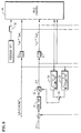
- a first embodiment of the invention is illustrated in Fig. 2, in which a pair of switches 26, 27 short circuit the dividers so as to provide a full measure of current commands to the inverter control 2B upon failure of the inverter 3.
- the switches 26, 27 are operated by a switch control output from a failure control circuit 30 which includes a failure detector 30 1 , an inverter switch control, 30 2 , and a switch control 30 3 .
- the failure detector 30 1 determines when there has been a failure in either of the inverters 2, 3, such as a fuse failure or damaging of the main circuit elements in the inverters.
- the switch control output from the failure control circuits 30 causes a switch 25 to transfer the limit control from the arithmetic function 23 to an arithmetic function 24 so as to base the torque current limit on the maximum current limitation allowed in a single inverter, I ILIM .
- the switch control output from the failure control circuits 30 also operates a selected one of a pair of motor switches 28, 29, so as to disconnect the motor 1 from the failed inverter (here assumed to be inverter 3).
- Fig. 2 The description of one aspect of the present invention with respect to Fig. 2 is illustrative of a special case of a double-wound motor being driven by two inverters.
- this aspect of the invention can tolerate the failure of M inverters, by providing divider circuits 31, 32 in which the divisor is (N-M).
- the limiting factor generated in the arithmetic function 24 is determined by the number of remaining inverters, N minus M.
- the values of (N-M) are provided by the inverter switch control circuits 30 in response to the number of inverters, M, which it has sensed have failed.
- FIG. 5 A second embodiment of the present invention is illustrated in Fig. 5.
- the relationship between the in phase current command i 1q , the quadrature current command i 1d , and the limiting current for an inverter I ILIM shows that the in-phase current component, which is the equivalent of the torque current command, I T *, is equal to the limiting current over the square root of two, by simple arithmetic.
- the voltage command generator 13 provides outputs which have added thereto the values ⁇ V 1q and ⁇ V 1d provided by the amplifiers 10, 11.
- the output of the amplifiers 10 and 11 will be significantly larger than such outputs would be with current feedback. This can have the effect of driving the pulse width modulation circuit 14 with higher voltage commands whenever the current feedback is turned off, in accordance with another aspect of the invention illustrated in Fig. 9 through Fig. 12.
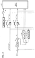
- Fig. 9 is similar to Fig. 2 except that no switches are provided to short circuit the dividers 8,9. Instead, a switch 35 allows a "feedback off" command to turn off the current feedback within the inverter control 2B.
- Reference to Fig. 1 shows that if the current feedback is turned off, the summing junctions at the inputs to the amplifiers 10, 11 will have nothing subtracted, so that the outputs of the amplifiers 10, 11 will be much higher than they normally would be, the motor drive being governed only by the speed feedback to the speed amplifier 21. This causes driving of the pulse width modulation circuit 14 more robustly than normal, in order to compensate for having the failed inverter turned off.
- the switch 35 is operated by the output of the failure control circuits 30, along with operating the other switches.
- Fig. 11 and Fig. 12 illustrate that this third aspect of the present invention can be practiced, with or without short circuiting dividers 31, 32, in the general case where more than two winding sets are used on the motor, driven by more than two corresponding inverters.
- a three-phase, N-wound induction motor 1 is driving a sheave 36 which is roped to an elevator car 37 and a counterweight 38.
- the car 37 moves with a velocity, V, illustrated in Fig. 14, and an acceleration, ⁇ .
- V illustrated in Fig. 14
- ⁇ an acceleration
- the solid line depicts a full speed run
- the dot-dash line illustrates a reduced speed run. It can be seen that the load torque T MR (supporting the load against the force of gravity) is constant at all speeds and rates of change of speed, and is the same whether a reduced speed profile is used or not.
- T P x 1000 1.027 x Nm
- T A (GD 2 x N M )/(375t a )
- This fourth embodiment of the invention may also be used in combination with the second aspect of the invention, as described hereinbefore with respect to Figs. 5-7.
Landscapes
- Engineering & Computer Science (AREA)
- Power Engineering (AREA)
- Control Of Ac Motors In General (AREA)
- Elevator Control (AREA)
Applications Claiming Priority (2)
| Application Number | Priority Date | Filing Date | Title |
|---|---|---|---|
| JP16805098 | 1998-06-16 | ||
| JP16805098A JP4187308B2 (ja) | 1998-06-16 | 1998-06-16 | 可変速駆動装置 |
Publications (3)
| Publication Number | Publication Date |
|---|---|
| EP0966094A2 true EP0966094A2 (fr) | 1999-12-22 |
| EP0966094A3 EP0966094A3 (fr) | 2002-03-06 |
| EP0966094B1 EP0966094B1 (fr) | 2007-03-07 |
Family
ID=15860910
Family Applications (1)
| Application Number | Title | Priority Date | Filing Date |
|---|---|---|---|
| EP19990111072 Expired - Lifetime EP0966094B1 (fr) | 1998-06-16 | 1999-06-16 | Fonctionnement réduit d'un moteur a induction à enroulment multiple en cas de pan d'onduleur |
Country Status (7)
| Country | Link |
|---|---|
| US (1) | US6158553A (fr) |
| EP (1) | EP0966094B1 (fr) |
| JP (1) | JP4187308B2 (fr) |
| CN (1) | CN1090837C (fr) |
| DE (1) | DE69935372T2 (fr) |
| MY (1) | MY133147A (fr) |
| TW (1) | TW483228B (fr) |
Cited By (5)
| Publication number | Priority date | Publication date | Assignee | Title |
|---|---|---|---|---|
| WO2004073157A3 (fr) * | 2003-02-06 | 2004-10-28 | Wavecrest Lab Llc | Moteurs electriques basse tension |
| SG108268A1 (en) * | 2000-08-11 | 2005-01-28 | Sumitomo Heavy Industries | Control unit of motor for injection molding machine |
| EP1591300A1 (fr) * | 2004-04-30 | 2005-11-02 | NSK Ltd. | Dispositif de commande pour direction assistée électrique |
| CN100369767C (zh) * | 2004-11-04 | 2008-02-20 | 丰田自动车株式会社 | 动力输出装置和包括该动力输出装置的车辆 |
| CN114325380A (zh) * | 2021-11-25 | 2022-04-12 | 合肥工业大学 | 一种永磁同步电机驱动系统故障诊断方法 |
Families Citing this family (47)
| Publication number | Priority date | Publication date | Assignee | Title |
|---|---|---|---|---|
| JP2002284464A (ja) * | 2001-03-27 | 2002-10-03 | Toshiba Elevator Co Ltd | エレベータの制御装置 |
| JP4780692B2 (ja) * | 2001-06-01 | 2011-09-28 | 株式会社Ihiエアロスペース | 多相モータ |
| US6737763B2 (en) * | 2001-12-17 | 2004-05-18 | Cloudshield Technologies, Inc. | Intelligent load sharing with power limiting scheme for multiple power supplies connected to a common load |
| US6661119B2 (en) | 2001-12-17 | 2003-12-09 | Cloudshield Technologies, Inc. | System and method for distributed power supply supporting high currents with redundancy |
| JP2004173338A (ja) * | 2002-11-18 | 2004-06-17 | Mitsubishi Electric Corp | インバータ装置 |
| JP2004236424A (ja) | 2003-01-30 | 2004-08-19 | Toyota Motor Corp | 動力出力装置、モータ駆動方法およびモータの駆動制御をコンピュータに実行させるためのプログラムを記録したコンピュータ読取り可能な記録媒体 |
| JP2005086918A (ja) * | 2003-09-09 | 2005-03-31 | Fanuc Ltd | モータ駆動装置 |
| JP4137854B2 (ja) * | 2004-07-30 | 2008-08-20 | ファナック株式会社 | 電動機の制御装置 |
| JP4749852B2 (ja) * | 2005-11-30 | 2011-08-17 | 日立オートモティブシステムズ株式会社 | モータ駆動装置及びそれを用いた自動車 |
| JP4867483B2 (ja) * | 2006-06-09 | 2012-02-01 | 日本精工株式会社 | モータ制御方法及び制御装置 |
| JP2008043046A (ja) * | 2006-08-07 | 2008-02-21 | Aida Eng Ltd | サーボモータの制御方法 |
| JP2008259302A (ja) * | 2007-04-04 | 2008-10-23 | Honda Motor Co Ltd | 電動機の制御装置 |
| JP4985956B2 (ja) * | 2007-04-13 | 2012-07-25 | 本田技研工業株式会社 | 電動機の制御装置 |
| JP5152742B2 (ja) * | 2007-04-24 | 2013-02-27 | 株式会社日立製作所 | 誘導電動機駆動装置 |
| JP5140462B2 (ja) * | 2008-03-10 | 2013-02-06 | 本田技研工業株式会社 | ブリッジ駆動回路 |
| JP5250755B2 (ja) * | 2008-03-25 | 2013-07-31 | 株式会社サンメディカル技術研究所 | 補助人工心臓ポンプ駆動装置及び補助人工心臓システム |
| JP5313604B2 (ja) * | 2008-09-19 | 2013-10-09 | 富士電機株式会社 | 電動機駆動装置 |
| JP5387989B2 (ja) * | 2009-12-25 | 2014-01-15 | 株式会社デンソー | 電動機駆動装置、および、これを用いた電動パワーステアリング装置 |
| JP5370139B2 (ja) * | 2009-12-25 | 2013-12-18 | 株式会社デンソー | 電動パワーステアリング装置 |
| WO2011158357A1 (fr) * | 2010-06-17 | 2011-12-22 | 三菱電機株式会社 | Appareil de commande d'ascenseur |
| JP5229645B2 (ja) * | 2010-06-24 | 2013-07-03 | 株式会社デンソー | 電動機駆動装置、および、これを用いた電動パワーステアリング装置 |
| JP5672936B2 (ja) | 2010-10-18 | 2015-02-18 | 株式会社ジェイテクト | 電動パワーステアリング装置 |
| EP2505833B1 (fr) * | 2011-03-29 | 2016-06-08 | Alstom Wind, S.L.U. | Éolienne avec système de calage de pale avec un actuateur à double bobine |
| JP5397785B2 (ja) * | 2011-08-01 | 2014-01-22 | 株式会社デンソー | 3相回転機の制御装置 |
| JP5950177B2 (ja) * | 2011-08-05 | 2016-07-13 | 富士電機株式会社 | 並列インバータ装置 |
| JP5440889B2 (ja) * | 2012-01-10 | 2014-03-12 | 株式会社デンソー | 電動パワーステアリング装置 |
| JP5436592B2 (ja) * | 2012-02-07 | 2014-03-05 | 三菱電機株式会社 | モータ制御装置、モータ制御装置に適用される電流制御方法、およびモータ制御装置を用いた電動パワーステアリング装置 |
| CN102868359A (zh) * | 2012-04-27 | 2013-01-09 | 李永盼 | 一种交流电机驱动器及传动装置 |
| EP2856631B1 (fr) * | 2012-05-25 | 2019-03-06 | The Switch Drive Systems Oy | Procédé et appareil de commande d'une machine électrique comprenant deux ou plusieurs enroulements statoriques polyphasés |
| JP5590076B2 (ja) * | 2012-07-04 | 2014-09-17 | 株式会社デンソー | 多相回転機の制御装置 |
| CN102916642A (zh) * | 2012-11-08 | 2013-02-06 | 江苏科技大学 | 永磁同步直线电机支持向量机内模容错控制系统及方法 |
| JP5892085B2 (ja) * | 2013-02-18 | 2016-03-23 | トヨタ自動車株式会社 | 移動体及びその制御方法 |
| JP2014176215A (ja) * | 2013-03-08 | 2014-09-22 | Nsk Ltd | モータ制御装置、これを使用した電動パワーステアリング装置及び車両 |
| JP2015039256A (ja) * | 2013-03-15 | 2015-02-26 | 日本精工株式会社 | モータ制御装置、これを使用した電動パワーステアリング装置及び車両 |
| WO2015095149A1 (fr) * | 2013-12-17 | 2015-06-25 | Corindus, Inc. | Système et procédé permettant de commander un moteur dans un système de procédure de cathéter |
| CN104022701B (zh) * | 2014-06-20 | 2016-09-07 | 福州大学 | 一种永磁同步直线电机牛顿法内模速度控制方法 |
| KR20160004764A (ko) * | 2014-07-04 | 2016-01-13 | 삼성전자주식회사 | 고장 허용 제어 시스템 |
| JP6040963B2 (ja) * | 2014-07-07 | 2016-12-07 | 株式会社デンソー | 回転機の制御装置 |
| JP5954366B2 (ja) | 2014-07-14 | 2016-07-20 | 日本精工株式会社 | モータ制御装置並びにそれを搭載した電動パワーステアリング装置及び車両 |
| JP6427443B2 (ja) * | 2015-03-12 | 2018-11-21 | 日立オートモティブシステムズ株式会社 | モータの駆動制御ユニット |
| JP6400528B2 (ja) * | 2015-05-27 | 2018-10-03 | 株式会社日立製作所 | エレベーター制御装置及びエレベーター |
| DE112017004959T5 (de) * | 2016-09-30 | 2019-06-13 | Nidec Corporation | Leistungsumwandlungsvorrichtung, Motoransteuereinheit und elektrische Servolenkungsvorrichtung |
| JP6778085B2 (ja) * | 2016-11-08 | 2020-10-28 | 東洋電機製造株式会社 | 電力変換装置 |
| JP7230488B2 (ja) * | 2018-12-21 | 2023-03-01 | 株式会社ジェイテクト | モータ制御装置 |
| WO2021100414A1 (fr) * | 2019-11-18 | 2021-05-27 | 日立Astemo株式会社 | Dispositif de conversion de puissance et procédé de diagnostic de défaut de dispositif de conversion de puissance |
| JP7491814B2 (ja) * | 2020-10-30 | 2024-05-28 | ナブテスコ株式会社 | Ac-acコンバータ |
| CN118833063A (zh) * | 2024-03-27 | 2024-10-25 | 华为数字能源技术有限公司 | 电机控制器、分布式动力总成、混合动力总成和车辆 |
Family Cites Families (13)
| Publication number | Priority date | Publication date | Assignee | Title |
|---|---|---|---|---|
| US3798530A (en) * | 1972-10-17 | 1974-03-19 | Gould Inc | Static switch circuit |
| DE2513227C3 (de) * | 1975-03-25 | 1978-05-03 | Siemens Ag, 1000 Berlin Und 8000 Muenchen | Schutzeinrichtung für einen Umrichter |
| US4441064A (en) * | 1981-12-18 | 1984-04-03 | General Electric Company | Twelve-pulse operation of a controlled current inverter motor drive |
| US4455522A (en) * | 1982-08-02 | 1984-06-19 | General Electric Company | Current source inverter bed induction motor drive |
| NL9101453A (nl) * | 1990-09-10 | 1992-04-01 | Barmag Barmer Maschf | Frequentie-omvormer. |
| JP3251628B2 (ja) * | 1992-03-06 | 2002-01-28 | 三菱電機株式会社 | エレベーターの速度制御装置 |
| JP2884942B2 (ja) * | 1992-09-17 | 1999-04-19 | 株式会社日立製作所 | 電気車制御装置 |
| FR2713565B1 (fr) * | 1993-12-13 | 1996-01-19 | Gec Alsthom Transport Sa | Système d'alimentation multicourant à haute disponibilité pour engin de locomotive ferroviaire. |
| JP2833460B2 (ja) * | 1993-12-27 | 1998-12-09 | 株式会社日立製作所 | 電源システム |
| US5569966A (en) * | 1994-06-10 | 1996-10-29 | Northrop Grumman Corporation | Electric vehicle propulsion system power bridge with built-in test |
| JP3330034B2 (ja) * | 1996-11-20 | 2002-09-30 | 株式会社日立製作所 | 電力変換装置 |
| JP3696384B2 (ja) * | 1997-09-16 | 2005-09-14 | 本田技研工業株式会社 | 電動機の駆動装置 |
| US6031298A (en) * | 1997-12-19 | 2000-02-29 | International Business Machines Corporation | 2N redundant power system and method using cross-coupled AC power transfer |
-
1998
- 1998-06-16 JP JP16805098A patent/JP4187308B2/ja not_active Expired - Fee Related
-
1999
- 1999-05-26 US US09/320,073 patent/US6158553A/en not_active Expired - Lifetime
- 1999-06-14 MY MYPI9902425 patent/MY133147A/en unknown
- 1999-06-16 DE DE1999635372 patent/DE69935372T2/de not_active Expired - Lifetime
- 1999-06-16 CN CN99108623A patent/CN1090837C/zh not_active Expired - Fee Related
- 1999-06-16 EP EP19990111072 patent/EP0966094B1/fr not_active Expired - Lifetime
- 1999-09-08 TW TW88110103A patent/TW483228B/zh active
Cited By (6)
| Publication number | Priority date | Publication date | Assignee | Title |
|---|---|---|---|---|
| SG108268A1 (en) * | 2000-08-11 | 2005-01-28 | Sumitomo Heavy Industries | Control unit of motor for injection molding machine |
| WO2004073157A3 (fr) * | 2003-02-06 | 2004-10-28 | Wavecrest Lab Llc | Moteurs electriques basse tension |
| EP1591300A1 (fr) * | 2004-04-30 | 2005-11-02 | NSK Ltd. | Dispositif de commande pour direction assistée électrique |
| CN100369767C (zh) * | 2004-11-04 | 2008-02-20 | 丰田自动车株式会社 | 动力输出装置和包括该动力输出装置的车辆 |
| CN114325380A (zh) * | 2021-11-25 | 2022-04-12 | 合肥工业大学 | 一种永磁同步电机驱动系统故障诊断方法 |
| CN114325380B (zh) * | 2021-11-25 | 2022-12-27 | 合肥工业大学 | 一种永磁同步电机驱动系统故障诊断方法 |
Also Published As
| Publication number | Publication date |
|---|---|
| JP2000004600A (ja) | 2000-01-07 |
| CN1090837C (zh) | 2002-09-11 |
| EP0966094B1 (fr) | 2007-03-07 |
| EP0966094A3 (fr) | 2002-03-06 |
| US6158553A (en) | 2000-12-12 |
| JP4187308B2 (ja) | 2008-11-26 |
| TW483228B (en) | 2002-04-11 |
| DE69935372D1 (de) | 2007-04-19 |
| HK1028681A1 (en) | 2001-02-23 |
| DE69935372T2 (de) | 2007-11-29 |
| CN1258128A (zh) | 2000-06-28 |
| MY133147A (en) | 2007-10-31 |
Similar Documents
| Publication | Publication Date | Title |
|---|---|---|
| US6158553A (en) | Curtailed operation of multiple-wound induction motor following inverter failure | |
| US6264005B1 (en) | Method for controlling rescue operation of elevator car during power failure | |
| EP0577980B1 (fr) | Mécanisme d'entraînement à vitesse variable pour courant alternatif et véhicule électrique utilisant celui-ci | |
| US5625262A (en) | System for equalizing the load of a plurality of motors | |
| CA2106174C (fr) | Systeme de commande pour vehicule electrique | |
| EP2355332A2 (fr) | Système et procédé de commande de moteur | |
| EP0401057A2 (fr) | Système d'entraînement à vitesse variable | |
| JPH0538182A (ja) | エレベーター装置 | |
| US4078191A (en) | Control system for regulating the torque and speed of an electric motor | |
| EP1060560B1 (fr) | Regulateur de moteur | |
| JP4146172B2 (ja) | エレベータの制御装置 | |
| US8242733B2 (en) | Asynchronous AC induction electrical machines in cross-interlockingly parallel connection | |
| US4815567A (en) | Apparatus for controlling an A.C. powered elevator | |
| US4306182A (en) | Polyphase motor drive system with balanced modulation | |
| JP4088734B2 (ja) | 永久磁石形同期電動機の制御装置 | |
| US4818890A (en) | Turbine helper drive apparatus | |
| US6903523B2 (en) | Methods and apparatus for dynamically reconfiguring a pulse width modulation approach | |
| JP3329873B2 (ja) | ロープレスエレベータ装置 | |
| US4634942A (en) | Apparatus for controlling electric cars | |
| US5880571A (en) | Method of and system for controlling a variable speed induction motor | |
| JPH09140187A (ja) | 電力変換装置 | |
| US5378952A (en) | Machine drive system and method | |
| US20080157703A1 (en) | Synchronous reluctance machines | |
| KR20040005122A (ko) | 전기자동차의 전동기 제어장치 및 방법 | |
| JP3105892B1 (ja) | クレーン装置 |
Legal Events
| Date | Code | Title | Description |
|---|---|---|---|
| PUAI | Public reference made under article 153(3) epc to a published international application that has entered the european phase |
Free format text: ORIGINAL CODE: 0009012 |
|
| AK | Designated contracting states |
Kind code of ref document: A2 Designated state(s): AT BE CH CY DE DK ES FI FR GB GR IE IT LI LU MC NL PT SE Kind code of ref document: A2 Designated state(s): DE FR GB |
|
| AX | Request for extension of the european patent |
Free format text: AL;LT;LV;MK;RO;SI |
|
| PUAL | Search report despatched |
Free format text: ORIGINAL CODE: 0009013 |
|
| AK | Designated contracting states |
Kind code of ref document: A3 Designated state(s): AT BE CH CY DE DK ES FI FR GB GR IE IT LI LU MC NL PT SE |
|
| AX | Request for extension of the european patent |
Free format text: AL;LT;LV;MK;RO;SI |
|
| RIC1 | Information provided on ipc code assigned before grant |
Free format text: 7H 02P 7/01 A, 7H 02P 7/00 B, 7B 66B 1/30 B, 7B 66B 5/00 B, 7B 66B 1/00 B, 7H 02P 21/00 B |
|
| 17P | Request for examination filed |
Effective date: 20020829 |
|
| AKX | Designation fees paid |
Free format text: DE FR GB |
|
| GRAP | Despatch of communication of intention to grant a patent |
Free format text: ORIGINAL CODE: EPIDOSNIGR1 |
|
| RIC1 | Information provided on ipc code assigned before grant |
Ipc: H02P 7/24 20060101ALI20060823BHEP Ipc: H02P 21/00 20060101ALI20060823BHEP Ipc: B66B 1/00 20060101ALI20060823BHEP Ipc: B66B 5/00 20060101ALI20060823BHEP Ipc: B66B 1/30 20060101AFI20060823BHEP |
|
| GRAS | Grant fee paid |
Free format text: ORIGINAL CODE: EPIDOSNIGR3 |
|
| GRAA | (expected) grant |
Free format text: ORIGINAL CODE: 0009210 |
|
| AK | Designated contracting states |
Kind code of ref document: B1 Designated state(s): DE FR GB |
|
| REG | Reference to a national code |
Ref country code: GB Ref legal event code: FG4D |
|
| REF | Corresponds to: |
Ref document number: 69935372 Country of ref document: DE Date of ref document: 20070419 Kind code of ref document: P |
|
| ET | Fr: translation filed | ||
| PLBE | No opposition filed within time limit |
Free format text: ORIGINAL CODE: 0009261 |
|
| STAA | Information on the status of an ep patent application or granted ep patent |
Free format text: STATUS: NO OPPOSITION FILED WITHIN TIME LIMIT |
|
| 26N | No opposition filed |
Effective date: 20071210 |
|
| REG | Reference to a national code |
Ref country code: FR Ref legal event code: PLFP Year of fee payment: 17 |
|
| PGFP | Annual fee paid to national office [announced via postgrant information from national office to epo] |
Ref country code: GB Payment date: 20150527 Year of fee payment: 17 Ref country code: DE Payment date: 20150521 Year of fee payment: 17 |
|
| PGFP | Annual fee paid to national office [announced via postgrant information from national office to epo] |
Ref country code: FR Payment date: 20150526 Year of fee payment: 17 |
|
| REG | Reference to a national code |
Ref country code: DE Ref legal event code: R119 Ref document number: 69935372 Country of ref document: DE |
|
| GBPC | Gb: european patent ceased through non-payment of renewal fee |
Effective date: 20160616 |
|
| REG | Reference to a national code |
Ref country code: FR Ref legal event code: ST Effective date: 20170228 |
|
| PG25 | Lapsed in a contracting state [announced via postgrant information from national office to epo] |
Ref country code: FR Free format text: LAPSE BECAUSE OF NON-PAYMENT OF DUE FEES Effective date: 20160630 Ref country code: DE Free format text: LAPSE BECAUSE OF NON-PAYMENT OF DUE FEES Effective date: 20170103 |
|
| PG25 | Lapsed in a contracting state [announced via postgrant information from national office to epo] |
Ref country code: GB Free format text: LAPSE BECAUSE OF NON-PAYMENT OF DUE FEES Effective date: 20160616 |