EP0967347B1 - Methode zur Sicherheitslastverankerung, besonders zum Heben von Betonplatten, und dazugehörige Kupplungsvorrichtung - Google Patents
Methode zur Sicherheitslastverankerung, besonders zum Heben von Betonplatten, und dazugehörige Kupplungsvorrichtung Download PDFInfo
- Publication number
- EP0967347B1 EP0967347B1 EP99111861A EP99111861A EP0967347B1 EP 0967347 B1 EP0967347 B1 EP 0967347B1 EP 99111861 A EP99111861 A EP 99111861A EP 99111861 A EP99111861 A EP 99111861A EP 0967347 B1 EP0967347 B1 EP 0967347B1
- Authority
- EP
- European Patent Office
- Prior art keywords
- bell
- shaped body
- bracket
- head
- recess
- Prior art date
- Legal status (The legal status is an assumption and is not a legal conclusion. Google has not performed a legal analysis and makes no representation as to the accuracy of the status listed.)
- Expired - Lifetime
Links
- 239000004567 concrete Substances 0.000 title claims abstract description 18
- 238000000034 method Methods 0.000 title claims abstract description 15
- 238000004873 anchoring Methods 0.000 title claims abstract description 13
- 230000008878 coupling Effects 0.000 title claims description 11
- 238000010168 coupling process Methods 0.000 title claims description 11
- 238000005859 coupling reaction Methods 0.000 title claims description 11
- 238000003780 insertion Methods 0.000 claims description 5
- 230000037431 insertion Effects 0.000 claims description 5
- 230000014759 maintenance of location Effects 0.000 claims description 4
- 229910000831 Steel Inorganic materials 0.000 claims description 3
- 238000005266 casting Methods 0.000 claims description 3
- 230000002787 reinforcement Effects 0.000 claims description 3
- 239000010959 steel Substances 0.000 claims description 3
- 238000010276 construction Methods 0.000 claims description 2
- 239000000725 suspension Substances 0.000 claims description 2
- 238000000605 extraction Methods 0.000 claims 1
- 239000000463 material Substances 0.000 claims 1
- 230000013011 mating Effects 0.000 description 3
- 239000011150 reinforced concrete Substances 0.000 description 2
- 239000004576 sand Substances 0.000 description 2
- 230000002860 competitive effect Effects 0.000 description 1
- 239000000470 constituent Substances 0.000 description 1
- 230000000694 effects Effects 0.000 description 1
- 229920006248 expandable polystyrene Polymers 0.000 description 1
- 238000009434 installation Methods 0.000 description 1
- 230000000670 limiting effect Effects 0.000 description 1
- 239000002184 metal Substances 0.000 description 1
- 230000036961 partial effect Effects 0.000 description 1
- 230000035515 penetration Effects 0.000 description 1
- 229920000642 polymer Polymers 0.000 description 1
- 239000011347 resin Substances 0.000 description 1
- 229920005989 resin Polymers 0.000 description 1
- 230000000284 resting effect Effects 0.000 description 1
- 230000000717 retained effect Effects 0.000 description 1
- 238000000926 separation method Methods 0.000 description 1
- 238000005303 weighing Methods 0.000 description 1
Images


Classifications
-
- B—PERFORMING OPERATIONS; TRANSPORTING
- B66—HOISTING; LIFTING; HAULING
- B66C—CRANES; LOAD-ENGAGING ELEMENTS OR DEVICES FOR CRANES, CAPSTANS, WINCHES, OR TACKLES
- B66C1/00—Load-engaging elements or devices attached to lifting or lowering gear of cranes or adapted for connection therewith for transmitting lifting forces to articles or groups of articles
- B66C1/10—Load-engaging elements or devices attached to lifting or lowering gear of cranes or adapted for connection therewith for transmitting lifting forces to articles or groups of articles by mechanical means
- B66C1/62—Load-engaging elements or devices attached to lifting or lowering gear of cranes or adapted for connection therewith for transmitting lifting forces to articles or groups of articles by mechanical means comprising article-engaging members of a shape complementary to that of the articles to be handled
- B66C1/66—Load-engaging elements or devices attached to lifting or lowering gear of cranes or adapted for connection therewith for transmitting lifting forces to articles or groups of articles by mechanical means comprising article-engaging members of a shape complementary to that of the articles to be handled for engaging holes, recesses, or abutments on articles specially provided for facilitating handling thereof
- B66C1/666—Load-engaging elements or devices attached to lifting or lowering gear of cranes or adapted for connection therewith for transmitting lifting forces to articles or groups of articles by mechanical means comprising article-engaging members of a shape complementary to that of the articles to be handled for engaging holes, recesses, or abutments on articles specially provided for facilitating handling thereof for connection to anchor inserts embedded in concrete structures
-
- E—FIXED CONSTRUCTIONS
- E04—BUILDING
- E04G—SCAFFOLDING; FORMS; SHUTTERING; BUILDING IMPLEMENTS OR AIDS, OR THEIR USE; HANDLING BUILDING MATERIALS ON THE SITE; REPAIRING, BREAKING-UP OR OTHER WORK ON EXISTING BUILDINGS
- E04G15/00—Forms or shutterings for making openings, cavities, slits, or channels
- E04G15/04—Cores for anchor holes or the like around anchors embedded in the concrete
-
- E—FIXED CONSTRUCTIONS
- E04—BUILDING
- E04G—SCAFFOLDING; FORMS; SHUTTERING; BUILDING IMPLEMENTS OR AIDS, OR THEIR USE; HANDLING BUILDING MATERIALS ON THE SITE; REPAIRING, BREAKING-UP OR OTHER WORK ON EXISTING BUILDINGS
- E04G21/00—Preparing, conveying, or working-up building materials or building elements in situ; Other devices or measures for constructional work
- E04G21/14—Conveying or assembling building elements
- E04G21/142—Means in or on the elements for connecting same to handling apparatus
Definitions
- This invention relates to a safety anchoring method, particularly for lifting concrete slabs, and to the coupling device for implementing the method.
- a known method which solves the problem is based on creating in the edge of the slab a semicircular recess from which there projects, by a distance such as not to pass beyond the edge of the slab, a holed end of a bracket embedded in the concrete.
- a special implement which hangs from the lifting cable and is lowerly recessed to house the holed projecting end of said bracket and to pass a latch through its hole.
- This latch is of toroidal shape and slides in an annular seat with an angular mnovement of 90°, operated manually by an external radial stem.
- An object of the present invention is to define a safety anchoring method, particularly for lifting concrete slabs, which is available at a cost competitive with the said known method.
- a further object is to define a method, as stated, which provides absolute safety in operation.
- a further object is to define a coupling device for implementing the said method, which is particularly functional.
- a further object is to define a coupling device, as stated, which cannot develop faults even as a result of possible negligence by the operators, who could involuntarily bring it into contact with sand.
- a safety anchoring method particularly for lifting concrete slabs, characterised by providing in their edges a grip of rectangular cross-section with symmetrical undercuts, for the purpose of anchoring onto it an appropriate lifting device by rotating this latter through 90°, said anchoring position then being stabilized by the descent onto the device of an annular oval member.
- the central oval hole in said member mates with an external conjugate oval profile of a conjugate seat present on the slab.
- the purpose of interposing the oval ring is to confine the angular anchoring position of the device on the grip to the position of the conjugate seat present on the slab, and hence to fix the orientation between the device and the grip rigid with the slab.
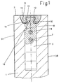
- a plain concrete or reinforced concrete product 1 is provided with an edge 2.
- An example of this product could be a slab, or a prefabricated wall for a house or industrial shed.
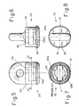
- This bracket can be formed from a usual rolled section of rectangular cross-section. The shape of this cross-section can be deduced indirectly from the thin line of the slot 4 of Figure 7, which mates with it as explained hereinafter.
- the bracket 3 has its foot 5 ( Figure 19) bent at an angle to improve its grip to the concrete in which it is embedded.
- the bracket also has holes 41 for the passage of any steel reinforcement rods 6, 7 ( Figure 1) for the slab.
- the bracket can also have recesses 8 for any cross reinforcements.
- the top of the bracket is inserted into a deformable or rubber element 9 which encloses it as an exact fit.
- a flat surface 14 can also be seen aligned with the edge 2.
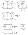
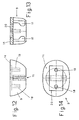
- the rubber element 9 has two notches 15 for facilitating the opening-out of the rubber element necessary for inserting into it the grips 12 and 13 of the bracket 3, ie the bracket head 16. These notches could be made on site by a usual knife. The presence of these notches makes the rubber element very deformable, hence in order to stiffen it during casting and to stabilize its retention on the bracket, there is associated with it a very rigid plate 17 of high-strength engineering polymer or of metal. This plate is shown in the three conventional views of Figures 15, 16, 17, and requires the rubber element 9 to be provided with holes 18, 19 and a rectangular recess 20 ( Figures 12, 13, 14).
- the function of the rubber element 9 is to create a geometrically constant and predetermined recess or cavity from which the bracket head 16 projects. The rubber element 9 is then removed as soon as the concrete sets to confine the bracket 3.
- the rubber element 9 is of disposable type, hence its construction and use could differ from the aforedescribed. For example it could be constructed of expandable polystyrene or another similar resin removable by tearing.
- a recess 21 remains from which a head 16 projects without passing beyond the edge 2, as shown in Figure 2.
- the slabs or the like generally have to be installed with contact between their edges 2, which have therefore to be straight and without projections.
- FIG 3 shows the coupling device in all its parts.
- a plate 22 provided with a hole 42 lowerly carries a U-shaped element 23 joined thereto by a weld 24. From the element 23 there hangs a bell-shaped body 25 provided with two opposing circumferential teeth 26A, 26B separated by the slot 4 (see Figure 7), to enable the bracket head 16 to be inserted when the bell-shaped body descends onto it with the movement 27.
- This insertion is possible only when the bell-shaped body 25 is correctly orientated in the horizontal plane, this orientation being such that the rectangular slot 4 of said body matches the likewise rectangular cross-section of the head 16. Correct orientation in said horizontal plane is made possible by the ability to angularly move the entire device about the vertical axis 28 on which it is suspended.
- the outer surface 29 of the bell-shaped body 25 is of elliptical or oval section. This can be better seen by comparison with the circular form of its base 30.
- the different circularity of the two surfaces 29 and 30 gives rise to a flat ledge 31.
- This flat ledge forms an abutment on which an interposing piece 32 rests ( Figure 3).
- This piece shown in Figures 9, 10, 11, has a central hole of oval shape similar to the outer surface 29 of the bell-shaped body 25. This is to enable the two surfaces 29 and 33 to mate and hence predetermine their mutual orientation.
- the interposing piece can slide vertically relative to the body 25. This enables it to attain a position 34 in which it is torsionally released from the body and in which it is retained by the manual retention action of the operator's finger 35.
- the device is lowered in the direction 27 while holding the interposing piece 32 raised (as shown in Figure 3) until the bracket head 16 has penetrated into the bell-shaped body 25.
- the bell-shaped body 25 is rotated through 90° about the vertical axis 28 (while also holding the plate 22), to hence cause its two circumferential teeth 26A, 26B to engage the undercut grips 12 and 13 present on the head 16 of the bracket 3.
- the piece 32 is allowed to descend freely into the recess 21, conjugate with it, which was previously formed in the concrete during the fixing of the bracket 3.
- This descent has as its aim the insertion of the piece 32 into the conjugate impression or recess 21, but at the same time is also conditional on the oval form of its hole 33 coinciding (ie is properly orientated) with the oval form of the surface 29 of the bell-shaped body 25.
- initial contact, with partial insertion takes place between the interposing piece 32 and the central bell-shaped body 25.
- this verticality presupposes items positioned with the bracket 3 vertical.
- prefabricated concrete slabs or walls are sometimes stacked horizontally. It follows that these have to be coupled on an axis of rotation 28 which is not vertical but horizontal, as is the bracket 3 in such a case. It subsequently becomes vertical when lifted, as the slab is brought into a vertical position.
- the item illustrated is a slab having its two large surfaces 37, 38 vertical, whereas they may previously lie horizontally, either resting on the ground or superimposed in typical stacks. While the slab is turning upright, a positive locking role is played by the roof 40 provided on the central cavity of the bell-shaped body 25, which can hence additionally engage the flat top of the head 16.
Landscapes
- Engineering & Computer Science (AREA)
- Architecture (AREA)
- Mechanical Engineering (AREA)
- Civil Engineering (AREA)
- Structural Engineering (AREA)
- Conveying And Assembling Of Building Elements In Situ (AREA)
- Load-Engaging Elements For Cranes (AREA)
- Moulds, Cores, Or Mandrels (AREA)
Claims (10)
- Sicherheitsverankerungsverfahren, insbesondere zum Heben einer Betonplatte oder -wand, dadurch gekennzeichnet, dass in einer Kante (2) der Platte oder der Wand eine Ausnehmung (21) von vorgegebener Form vorgesehen wird, aus der der Kopf (16) einer Klammer (3) vorragt, die in den Beton der Platte oder der Wand eingebettet ist und mit Griffen (12, 13) mit Unterschneidungen zu dem Zweck versehen ist, um einen glockenförmigen Körper (26) mit Zähnen (26A, 26B) an dem Kopf (16) der Klammer (3) zu verankern, indem der glockenförmige Körper, nach Einführen des Klammerkopfes (16) dorthinein durch einen geeigneten komplementären Schlitz (4), um 90° gedreht wird, wobei die eingenommene relative Verankerungsposition zwischen dem Klammerkopf (16) und dem glockenförmigen Körper (25) durch das Absenken (27) eines Zwischenstücks (32) auf die Außenseite des glockenförmigen Körpers stabilisiert wird, wobei das Zwischenstück (32) eine zentrale Antirotationsöffnung (33), die zu der Außenfläche (29) des glockenförmigen Körpers (25) passt, und eine Außenfläche hat, die zu der Ausnehmung (21) mit Antirotationsform passt, die in der Kante (2) der Platte oder Wand (1) vorhanden ist, wobei der Zweck, das Zwischenteil (32) in der Ausnehmung dazwischenzusetzen, darin besteht, die Winkelverankerungsstellung des glockenförmigen Körpers (25) mit seinen Zähnen (26A, 26B) in Eingriff mit den Griffen (12, 13) des Kopfs (16) auf die Winkelstellung der Ausnehmung (21) einzuschränken und daher die Orientierung des glockenförmigen Körpers (25) in Eingriff mit dem Klammerkopf relativ zu dem Kopf (16) selbst zu fixieren, wobei der Kopf starr in Bezug auf die Ausnehmung (21) ist, die das Zwischenstück (32) verdrehungsfest (28) mit dem glockenförmigen Körper enthält.
- Verfahren nach dem vorhergehenden Anspruch, dadurch gekennzeichnet, dass eine Ausnehmung (21) während des Gießens des Betons durch ein Abruckelement (9) gebildet wird, das an dem Klammerkopf (16) zu befestigen ist und das mit seiner flachen Oberfläche (14) ausgerichtet mit der Kante (2) der in Herstellung befindlichen Platte positionierbar ist, wobei das Abdruckelement aus einem elastischen oder zerreißbaren Material hergestellt ist, damit es entfernt werden kann, wenn der Beton ausgehärtet ist, wobei das Element dazu in der Lage ist, durch ein Versteifungsstück (17) ergänzt zu werden, das entfernt werden kann, um das Element auf den Kopf (16) der Klammer (3) aufzusetzen oder davon zu entfernen.
- Kupplungsvorrichtung zur Ausführung des Verfahrens nach den vorhergehenden Ansprüchen, gekennzeichnet durch eine Platte (22), die dazu bestimmt ist, an einer üblichen Aufhängeoder Hebeeinrichtung (36) befestigt zu werden, und die unten mit einem U-förmigen Element (23) versehen ist, um, durch eine Verbindung vom Kettengliedtyp, einen glockenförmigen Körper (25) zu tragen, der mit Zähnen (26A, 26B) versehen ist und in Eingriff mit Griffen (12, 13) an dem Kopf (16) einer Klammer (3) bringbar ist, indem er nach dem Einführen des Kopfes (16) in den glockenförmigen Körper (25) durch einen geeigneten komplementären Schlitz (4) um 90° gedreht wird, wobei der glockenförmige Körper außen ein Zwischenstück (32) trägt, das eine Antirotationsöffnung (33) komplementär zu einer äußeren Oberfläche (29) des Körpers (25) hat und mit seiner äußeren Antirotationsform gegen Verdrehung durch eine Ausnehmung (21) festsetzbar ist, die das Zwischenstück (32) stabil aufnimmt, wenn es vollständig mit der spezifischen Oberfläche (29) des glockenförmigen Körpers (25) zusammengefügt ist.
- Vorrichtung wie im vorhergehenden Anspruch beansprucht, dadurch gekennzeichnet, dass eine Antirotationsoberfläche (29) auf dem glockenförmigen Körper und die komplementäre Öffnung (33) in dem Zwischenstück (32) ovale Form haben.
- Vorrichtung wie in den vorhergehenden Ansprüchen 3 oder 4 beansprucht, dadurch gekennzeichnet, dass die äußere Oberfläche des Zwischenstücks (32) und die komplementäre Oberfläche der Ausnehmung (21), die zu ihrer Aufnahme vorgesehen ist, eiförmig sind.
- Vorrichtung wie in den vorhergehenden Ansprüchen 3 bis 5 beansprucht, dadurch gekennzeichnet, dass die Zähne, die mit dem glockenförmigen Körper eingreifen, halbkreisförmig in der Form (26A, 26B) sind.
- Vorrichtung wie in den vorhergehenden Ansprüche 3 bis 6 beansprucht, dadurch gekennzeichnet, dass der glockenförmige Körper (25) eine kreisförmige Basis (30) hat, die flache Vorsprünge (31) mit dem darüberliegenden Antirotationsabschnitt (29) bildet, die als Trägerflächen für das Zwischenstück (32) dienen, wenn es sich in seiner Ruhestellung befindet.
- Vorrichtung wie in den vorhergehenden Ansprüchen 3 bis 7 beansprucht, dadurch gekennzeichnet, dass sie an dem Klammerkopf (16) Griffe (12, 13) aufweist, die schräge Oberflächen zum Eingreifen mit den Zähnen (26A, 26B) des glockenförmigen Körpers aufweisen, um gegensätzliche Druckkraftkomponenten zu erzeugen, um die Rückhaltereibung zwischen den ineinandergreifenden Teilen zu unterstützen, die proportional zum Gewicht der getragenen Platte (1) ist.
- Vorrichtung wie in den vorhergehenden Ansprüchen 3 bis 8 beansprucht, dadurch gekennzeichnet, dass der Klammerkopf einen rechteckigen Querschnitt (4) hat.
- Vorrichtung wie in den vorhergehenden Ansprüchen 3 bis 9 beansprucht, gekennzeichnet durch eine Klammer (3), die mit Löchern (41) und Ausnehmungen (8) zur Aufnahme von Stahlverstärkungsstangen (6, 7) und durch einen im Winkel gebogenen Anti-Extraktions-Fuß versehen ist.
Applications Claiming Priority (2)
| Application Number | Priority Date | Filing Date | Title |
|---|---|---|---|
| IT1998BG000035A IT1305797B1 (it) | 1998-06-25 | 1998-06-25 | Metodo di ancoraggio di sicurezza particolarmante per il sollevamentodi lastroni in calcestruzzo e congegno di aggancio attuativo di esso. |
| ITBG980035 | 1998-06-25 |
Publications (2)
| Publication Number | Publication Date |
|---|---|
| EP0967347A1 EP0967347A1 (de) | 1999-12-29 |
| EP0967347B1 true EP0967347B1 (de) | 2004-01-21 |
Family
ID=11336614
Family Applications (1)
| Application Number | Title | Priority Date | Filing Date |
|---|---|---|---|
| EP99111861A Expired - Lifetime EP0967347B1 (de) | 1998-06-25 | 1999-06-21 | Methode zur Sicherheitslastverankerung, besonders zum Heben von Betonplatten, und dazugehörige Kupplungsvorrichtung |
Country Status (5)
| Country | Link |
|---|---|
| EP (1) | EP0967347B1 (de) |
| AT (1) | ATE258265T1 (de) |
| DE (1) | DE69914262D1 (de) |
| ES (1) | ES2214772T3 (de) |
| IT (1) | IT1305797B1 (de) |
Families Citing this family (7)
| Publication number | Priority date | Publication date | Assignee | Title |
|---|---|---|---|---|
| AT508219B1 (de) * | 2009-04-17 | 2011-01-15 | Ebawe Anlagentechnik Gmbh | Verfahren zum bewegen von betonfertigbauteilen |
| AU2011342373B2 (en) | 2010-12-14 | 2013-05-23 | Weir Minerals Australia Ltd | Lifter bar with attachment point for hoisting |
| AU2013202639B2 (en) * | 2010-12-14 | 2016-07-07 | Weir Minerals Australia Ltd | Lifter bar with attachment point for hoisting |
| DE102017127185A1 (de) * | 2017-11-17 | 2019-05-23 | ACO Severin Ahlmann GmbH & Co Kommanditgesellschaft | Verbundelement für den Hochbau oder Tiefbau und Verwendung von einem als Klemmelement ausgebildeten Befestigungselement |
| CN110409723A (zh) * | 2019-04-29 | 2019-11-05 | 中冶天工集团天津有限公司 | 一种装配式楼梯安装支架及其安装方法 |
| MX2022001473A (es) * | 2019-08-02 | 2022-08-04 | Brandsafway Services Llc | Punto de suspensión giratorio para utilizarse con anclajes para concreto. |
| EP4459072A1 (de) * | 2023-05-05 | 2024-11-06 | Nordex Energy Spain, S.A.U. | Aussparungsformer zum giessen einer aussparung in einem betonsegment und verfahren zum giessen einer aussparung in einem betonsegment |
Family Cites Families (4)
| Publication number | Priority date | Publication date | Assignee | Title |
|---|---|---|---|---|
| AT320256B (de) * | 1972-06-24 | 1975-02-10 | Mannesmann Leichtbau Gmbh | Bausatz aus Trägen unterschiedlicher Profilierung zum Transport, Verlegen und Befestigen von Kunststeinelementen sowie Kupplungselement für die Ankerprofilträger eines solchen Bausatzes |
| FR2504900B1 (fr) * | 1981-04-30 | 1986-05-02 | Moreau Pierre | Dispositif pour la manutention de charges notamment des elements de construction en beton |
| DE3629772A1 (de) * | 1986-09-02 | 1988-03-03 | Siegfried Fricker | Formkoerper zur halterung eines ankers beim betonieren eines betonfertigteiles |
| IT1284894B1 (it) * | 1996-09-30 | 1998-05-28 | Sergio Zambelli | Dispositivo per il sollevamento di manufatti prefabbricati in particolare in calcestruzzo o simili |
-
1998
- 1998-06-25 IT IT1998BG000035A patent/IT1305797B1/it active
-
1999
- 1999-06-21 EP EP99111861A patent/EP0967347B1/de not_active Expired - Lifetime
- 1999-06-21 ES ES99111861T patent/ES2214772T3/es not_active Expired - Lifetime
- 1999-06-21 DE DE69914262T patent/DE69914262D1/de not_active Expired - Lifetime
- 1999-06-21 AT AT99111861T patent/ATE258265T1/de not_active IP Right Cessation
Also Published As
| Publication number | Publication date |
|---|---|
| IT1305797B1 (it) | 2001-05-16 |
| DE69914262D1 (de) | 2004-02-26 |
| EP0967347A1 (de) | 1999-12-29 |
| ITBG980035A0 (it) | 1998-06-25 |
| ITBG980035A1 (it) | 1999-12-25 |
| ATE258265T1 (de) | 2004-02-15 |
| ES2214772T3 (es) | 2004-09-16 |
Similar Documents
| Publication | Publication Date | Title |
|---|---|---|
| CA2740498C (en) | A lifting device and method for concrete elements | |
| KR930001033B1 (ko) | 지주의 연결방법 및 지주장치 | |
| US4367892A (en) | Lift system for tilt-up walls | |
| US4417425A (en) | Apparatus for erecting concrete wall panels | |
| US4872298A (en) | Concrete anchor bolt setting device | |
| US8291649B2 (en) | Double anchor and lifting shackle for concrete slabs | |
| EP0231362A4 (de) | Hebezeugverbindung. | |
| EP0967347A1 (de) | Methode zur Sicherheitslastverankerung, besonders zum Heben von Betonplatten, und dazugehörige Kupplungsvorrichtung | |
| KR100892615B1 (ko) | 갱폼 안전 인양 시스템 | |
| EP2743426A1 (de) | Einbettbarer sicherheitsanker | |
| WO2003021059A1 (en) | Orientation apparatus | |
| AU2002334462A1 (en) | Orientation apparatus | |
| CA1037236A (en) | Method and means for supporting an elevated concrete wall panel form | |
| KR101991906B1 (ko) | 상하 커버를 구비한 갱폼 안전장치 | |
| KR101587908B1 (ko) | 인양 고리 장치 | |
| KR102455291B1 (ko) | 갱폼 낙하방지용 안전장치 | |
| JP2000160845A (ja) | スラブ配管孔の蓋 | |
| AU718399B3 (en) | Improvements to formwork | |
| KR200433916Y1 (ko) | 매립 지지콘의 커플링을 이용한 벽면 시공용 갱폼 낙하방지 구조 | |
| CA1203396A (en) | Apparatus for forming a recess about an anchor embedded in concrete | |
| US20240217137A1 (en) | Recess former and anchor assembly | |
| KR100750535B1 (ko) | 강재 거푸집 밸런스러그 | |
| KR100822347B1 (ko) | 갱폼 낙하방지용 안전장치 | |
| AU770232B2 (en) | Improvements to formwork | |
| GB2461599A (en) | Removable post assembly |
Legal Events
| Date | Code | Title | Description |
|---|---|---|---|
| PUAI | Public reference made under article 153(3) epc to a published international application that has entered the european phase |
Free format text: ORIGINAL CODE: 0009012 |
|
| AK | Designated contracting states |
Kind code of ref document: A1 Designated state(s): AT CH DE ES FR GR LI |
|
| AX | Request for extension of the european patent |
Free format text: AL;LT;LV;MK;RO;SI |
|
| 17P | Request for examination filed |
Effective date: 20000412 |
|
| AKX | Designation fees paid |
Free format text: AT CH DE ES FR GR LI |
|
| AXX | Extension fees paid |
Free format text: AL PAYMENT 20000529;SI PAYMENT 20000529 |
|
| GRAH | Despatch of communication of intention to grant a patent |
Free format text: ORIGINAL CODE: EPIDOS IGRA |
|
| GRAH | Despatch of communication of intention to grant a patent |
Free format text: ORIGINAL CODE: EPIDOS IGRA |
|
| RAP1 | Party data changed (applicant data changed or rights of an application transferred) |
Owner name: SAMER S.R.L. |
|
| GRAA | (expected) grant |
Free format text: ORIGINAL CODE: 0009210 |
|
| AK | Designated contracting states |
Kind code of ref document: B1 Designated state(s): AT CH DE ES FR GR LI |
|
| AX | Request for extension of the european patent |
Extension state: AL SI |
|
| PG25 | Lapsed in a contracting state [announced via postgrant information from national office to epo] |
Ref country code: LI Free format text: LAPSE BECAUSE OF FAILURE TO SUBMIT A TRANSLATION OF THE DESCRIPTION OR TO PAY THE FEE WITHIN THE PRESCRIBED TIME-LIMIT Effective date: 20040121 Ref country code: FR Free format text: LAPSE BECAUSE OF FAILURE TO SUBMIT A TRANSLATION OF THE DESCRIPTION OR TO PAY THE FEE WITHIN THE PRESCRIBED TIME-LIMIT Effective date: 20040121 Ref country code: CH Free format text: LAPSE BECAUSE OF FAILURE TO SUBMIT A TRANSLATION OF THE DESCRIPTION OR TO PAY THE FEE WITHIN THE PRESCRIBED TIME-LIMIT Effective date: 20040121 Ref country code: AT Free format text: LAPSE BECAUSE OF FAILURE TO SUBMIT A TRANSLATION OF THE DESCRIPTION OR TO PAY THE FEE WITHIN THE PRESCRIBED TIME-LIMIT Effective date: 20040121 |
|
| REG | Reference to a national code |
Ref country code: CH Ref legal event code: EP |
|
| REF | Corresponds to: |
Ref document number: 69914262 Country of ref document: DE Date of ref document: 20040226 Kind code of ref document: P |
|
| PG25 | Lapsed in a contracting state [announced via postgrant information from national office to epo] |
Ref country code: GR Free format text: LAPSE BECAUSE OF FAILURE TO SUBMIT A TRANSLATION OF THE DESCRIPTION OR TO PAY THE FEE WITHIN THE PRESCRIBED TIME-LIMIT Effective date: 20040421 |
|
| PG25 | Lapsed in a contracting state [announced via postgrant information from national office to epo] |
Ref country code: DE Free format text: LAPSE BECAUSE OF FAILURE TO SUBMIT A TRANSLATION OF THE DESCRIPTION OR TO PAY THE FEE WITHIN THE PRESCRIBED TIME-LIMIT Effective date: 20040422 |
|
| REG | Reference to a national code |
Ref country code: CH Ref legal event code: PL |
|
| REG | Reference to a national code |
Ref country code: ES Ref legal event code: FG2A Ref document number: 2214772 Country of ref document: ES Kind code of ref document: T3 |
|
| PLBE | No opposition filed within time limit |
Free format text: ORIGINAL CODE: 0009261 |
|
| STAA | Information on the status of an ep patent application or granted ep patent |
Free format text: STATUS: NO OPPOSITION FILED WITHIN TIME LIMIT |
|
| 26N | No opposition filed |
Effective date: 20041022 |
|
| EN | Fr: translation not filed | ||
| EN | Fr: translation not filed | ||
| REG | Reference to a national code |
Ref country code: FR Ref legal event code: ERR Free format text: BOPI DE PUBLICATION N: 05/03 PAGES: 237 PARTIE DU BULLETIN CONCERNEE: BREVETS EUROPEENS DONT LA TRADUCTION N'A PAS ETE REMISE A I'INPI IL Y A LIEU DE SUPPRIMER: LA MENTION DE LA NON REMISE. |
|
| PGFP | Annual fee paid to national office [announced via postgrant information from national office to epo] |
Ref country code: ES Payment date: 20060619 Year of fee payment: 8 |
|
| REG | Reference to a national code |
Ref country code: ES Ref legal event code: FD2A Effective date: 20070622 |
|
| PG25 | Lapsed in a contracting state [announced via postgrant information from national office to epo] |
Ref country code: ES Free format text: LAPSE BECAUSE OF NON-PAYMENT OF DUE FEES Effective date: 20070622 |