EP0967373A2 - Brennkraftmaschine - Google Patents
Brennkraftmaschine Download PDFInfo
- Publication number
- EP0967373A2 EP0967373A2 EP99111890A EP99111890A EP0967373A2 EP 0967373 A2 EP0967373 A2 EP 0967373A2 EP 99111890 A EP99111890 A EP 99111890A EP 99111890 A EP99111890 A EP 99111890A EP 0967373 A2 EP0967373 A2 EP 0967373A2
- Authority
- EP
- European Patent Office
- Prior art keywords
- amount
- combustion
- operation area
- fuel ratio
- engine
- Prior art date
- Legal status (The legal status is an assumption and is not a legal conclusion. Google has not performed a legal analysis and makes no representation as to the accuracy of the status listed.)
- Granted
Links
- 238000002485 combustion reaction Methods 0.000 title claims abstract description 343
- 239000000446 fuel Substances 0.000 claims abstract description 349
- 239000004071 soot Substances 0.000 claims abstract description 98
- MWUXSHHQAYIFBG-UHFFFAOYSA-N nitrogen oxide Inorganic materials O=[N] MWUXSHHQAYIFBG-UHFFFAOYSA-N 0.000 claims description 444
- 239000007789 gas Substances 0.000 claims description 191
- 239000011261 inert gas Substances 0.000 claims description 32
- 230000007423 decrease Effects 0.000 claims description 11
- 230000003134 recirculating effect Effects 0.000 claims description 7
- 230000003247 decreasing effect Effects 0.000 claims description 6
- 239000000498 cooling water Substances 0.000 claims description 5
- 239000007924 injection Substances 0.000 description 83
- 238000002347 injection Methods 0.000 description 83
- 238000000034 method Methods 0.000 description 64
- 230000008569 process Effects 0.000 description 62
- 230000006870 function Effects 0.000 description 55
- 239000002250 absorbent Substances 0.000 description 45
- 230000002745 absorbent Effects 0.000 description 45
- 229930195733 hydrocarbon Natural products 0.000 description 32
- 150000002430 hydrocarbons Chemical class 0.000 description 32
- 239000004215 Carbon black (E152) Substances 0.000 description 31
- 230000006835 compression Effects 0.000 description 30
- 238000007906 compression Methods 0.000 description 30
- 239000000779 smoke Substances 0.000 description 29
- BASFCYQUMIYNBI-UHFFFAOYSA-N platinum Chemical compound [Pt] BASFCYQUMIYNBI-UHFFFAOYSA-N 0.000 description 24
- 238000012937 correction Methods 0.000 description 23
- 239000003054 catalyst Substances 0.000 description 22
- 238000003795 desorption Methods 0.000 description 14
- 238000007254 oxidation reaction Methods 0.000 description 13
- 101100129496 Arabidopsis thaliana CYP711A1 gene Proteins 0.000 description 12
- 101100083446 Danio rerio plekhh1 gene Proteins 0.000 description 12
- 229910052757 nitrogen Inorganic materials 0.000 description 12
- 230000003647 oxidation Effects 0.000 description 12
- 238000001816 cooling Methods 0.000 description 11
- 239000000203 mixture Substances 0.000 description 11
- 239000002243 precursor Substances 0.000 description 11
- 229910052697 platinum Inorganic materials 0.000 description 10
- 238000011144 upstream manufacturing Methods 0.000 description 10
- 238000010586 diagram Methods 0.000 description 8
- 101100129499 Arabidopsis thaliana MAX2 gene Proteins 0.000 description 7
- QVGXLLKOCUKJST-UHFFFAOYSA-N atomic oxygen Chemical compound [O] QVGXLLKOCUKJST-UHFFFAOYSA-N 0.000 description 7
- 238000005304 joining Methods 0.000 description 7
- 239000001301 oxygen Substances 0.000 description 7
- 229910052760 oxygen Inorganic materials 0.000 description 7
- 230000008859 change Effects 0.000 description 6
- 230000003111 delayed effect Effects 0.000 description 6
- 239000012899 standard injection Substances 0.000 description 6
- UGFAIRIUMAVXCW-UHFFFAOYSA-N Carbon monoxide Chemical compound [O+]#[C-] UGFAIRIUMAVXCW-UHFFFAOYSA-N 0.000 description 5
- 229910002091 carbon monoxide Inorganic materials 0.000 description 5
- 230000001133 acceleration Effects 0.000 description 4
- 230000003197 catalytic effect Effects 0.000 description 4
- 239000006185 dispersion Substances 0.000 description 4
- 230000000694 effects Effects 0.000 description 4
- XLYOFNOQVPJJNP-UHFFFAOYSA-N water Substances O XLYOFNOQVPJJNP-UHFFFAOYSA-N 0.000 description 4
- 238000010521 absorption reaction Methods 0.000 description 3
- QVQLCTNNEUAWMS-UHFFFAOYSA-N barium oxide Chemical compound [Ba]=O QVQLCTNNEUAWMS-UHFFFAOYSA-N 0.000 description 3
- 238000007599 discharging Methods 0.000 description 3
- 229910017604 nitric acid Inorganic materials 0.000 description 3
- 239000002245 particle Substances 0.000 description 3
- GRYLNZFGIOXLOG-UHFFFAOYSA-N Nitric acid Chemical compound O[N+]([O-])=O GRYLNZFGIOXLOG-UHFFFAOYSA-N 0.000 description 2
- 229910052784 alkaline earth metal Inorganic materials 0.000 description 2
- 150000001342 alkaline earth metals Chemical class 0.000 description 2
- 229910052788 barium Inorganic materials 0.000 description 2
- DSAJWYNOEDNPEQ-UHFFFAOYSA-N barium atom Chemical compound [Ba] DSAJWYNOEDNPEQ-UHFFFAOYSA-N 0.000 description 2
- 239000011575 calcium Substances 0.000 description 2
- 238000001704 evaporation Methods 0.000 description 2
- 230000008020 evaporation Effects 0.000 description 2
- 238000002474 experimental method Methods 0.000 description 2
- 150000002500 ions Chemical class 0.000 description 2
- 230000007246 mechanism Effects 0.000 description 2
- 229910052751 metal Inorganic materials 0.000 description 2
- 239000002184 metal Substances 0.000 description 2
- 229910000510 noble metal Inorganic materials 0.000 description 2
- 230000010349 pulsation Effects 0.000 description 2
- 229910052761 rare earth metal Inorganic materials 0.000 description 2
- 150000002910 rare earth metals Chemical class 0.000 description 2
- 230000000630 rising effect Effects 0.000 description 2
- 229920006395 saturated elastomer Polymers 0.000 description 2
- 239000011734 sodium Substances 0.000 description 2
- 230000007704 transition Effects 0.000 description 2
- OYPRJOBELJOOCE-UHFFFAOYSA-N Calcium Chemical compound [Ca] OYPRJOBELJOOCE-UHFFFAOYSA-N 0.000 description 1
- 101000760620 Homo sapiens Cell adhesion molecule 1 Proteins 0.000 description 1
- 101000710013 Homo sapiens Reversion-inducing cysteine-rich protein with Kazal motifs Proteins 0.000 description 1
- 101000661816 Homo sapiens Suppression of tumorigenicity 18 protein Proteins 0.000 description 1
- DGAQECJNVWCQMB-PUAWFVPOSA-M Ilexoside XXIX Chemical compound C[C@@H]1CC[C@@]2(CC[C@@]3(C(=CC[C@H]4[C@]3(CC[C@@H]5[C@@]4(CC[C@@H](C5(C)C)OS(=O)(=O)[O-])C)C)[C@@H]2[C@]1(C)O)C)C(=O)O[C@H]6[C@@H]([C@H]([C@@H]([C@H](O6)CO)O)O)O.[Na+] DGAQECJNVWCQMB-PUAWFVPOSA-M 0.000 description 1
- WHXSMMKQMYFTQS-UHFFFAOYSA-N Lithium Chemical compound [Li] WHXSMMKQMYFTQS-UHFFFAOYSA-N 0.000 description 1
- ZLMJMSJWJFRBEC-UHFFFAOYSA-N Potassium Chemical compound [K] ZLMJMSJWJFRBEC-UHFFFAOYSA-N 0.000 description 1
- 239000006096 absorbing agent Substances 0.000 description 1
- 230000002776 aggregation Effects 0.000 description 1
- 238000004220 aggregation Methods 0.000 description 1
- PNEYBMLMFCGWSK-UHFFFAOYSA-N aluminium oxide Inorganic materials [O-2].[O-2].[O-2].[Al+3].[Al+3] PNEYBMLMFCGWSK-UHFFFAOYSA-N 0.000 description 1
- 238000013459 approach Methods 0.000 description 1
- 150000004945 aromatic hydrocarbons Chemical class 0.000 description 1
- 229910052792 caesium Inorganic materials 0.000 description 1
- TVFDJXOCXUVLDH-UHFFFAOYSA-N caesium atom Chemical compound [Cs] TVFDJXOCXUVLDH-UHFFFAOYSA-N 0.000 description 1
- 229910052791 calcium Inorganic materials 0.000 description 1
- 125000004432 carbon atom Chemical group C* 0.000 description 1
- 229910002092 carbon dioxide Inorganic materials 0.000 description 1
- XXLDWSKFRBJLMX-UHFFFAOYSA-N carbon dioxide;carbon monoxide Chemical compound O=[C].O=C=O XXLDWSKFRBJLMX-UHFFFAOYSA-N 0.000 description 1
- 238000006243 chemical reaction Methods 0.000 description 1
- 238000009841 combustion method Methods 0.000 description 1
- 230000001419 dependent effect Effects 0.000 description 1
- 238000013461 design Methods 0.000 description 1
- 230000006866 deterioration Effects 0.000 description 1
- 230000001747 exhibiting effect Effects 0.000 description 1
- 238000004880 explosion Methods 0.000 description 1
- 239000002737 fuel gas Substances 0.000 description 1
- 108090000237 interleukin-24 Proteins 0.000 description 1
- 229910052746 lanthanum Inorganic materials 0.000 description 1
- FZLIPJUXYLNCLC-UHFFFAOYSA-N lanthanum atom Chemical compound [La] FZLIPJUXYLNCLC-UHFFFAOYSA-N 0.000 description 1
- 229910052744 lithium Inorganic materials 0.000 description 1
- 238000004519 manufacturing process Methods 0.000 description 1
- 238000012986 modification Methods 0.000 description 1
- 230000004048 modification Effects 0.000 description 1
- 230000001590 oxidative effect Effects 0.000 description 1
- 230000002093 peripheral effect Effects 0.000 description 1
- 229910052700 potassium Inorganic materials 0.000 description 1
- 239000011591 potassium Substances 0.000 description 1
- 238000010926 purge Methods 0.000 description 1
- 230000009467 reduction Effects 0.000 description 1
- 238000011160 research Methods 0.000 description 1
- 230000004044 response Effects 0.000 description 1
- 229910052708 sodium Inorganic materials 0.000 description 1
- 239000007787 solid Substances 0.000 description 1
- 230000001131 transforming effect Effects 0.000 description 1
- 229910052727 yttrium Inorganic materials 0.000 description 1
- VWQVUPCCIRVNHF-UHFFFAOYSA-N yttrium atom Chemical compound [Y] VWQVUPCCIRVNHF-UHFFFAOYSA-N 0.000 description 1
Images


Classifications
-
- F—MECHANICAL ENGINEERING; LIGHTING; HEATING; WEAPONS; BLASTING
- F02—COMBUSTION ENGINES; HOT-GAS OR COMBUSTION-PRODUCT ENGINE PLANTS
- F02D—CONTROLLING COMBUSTION ENGINES
- F02D41/00—Electrical control of supply of combustible mixture or its constituents
- F02D41/30—Controlling fuel injection
- F02D41/3011—Controlling fuel injection according to or using specific or several modes of combustion
-
- F—MECHANICAL ENGINEERING; LIGHTING; HEATING; WEAPONS; BLASTING
- F02—COMBUSTION ENGINES; HOT-GAS OR COMBUSTION-PRODUCT ENGINE PLANTS
- F02D—CONTROLLING COMBUSTION ENGINES
- F02D21/00—Controlling engines characterised by their being supplied with non-airborne oxygen or other non-fuel gas
- F02D21/06—Controlling engines characterised by their being supplied with non-airborne oxygen or other non-fuel gas peculiar to engines having other non-fuel gas added to combustion air
- F02D21/08—Controlling engines characterised by their being supplied with non-airborne oxygen or other non-fuel gas peculiar to engines having other non-fuel gas added to combustion air the other gas being the exhaust gas of engine
-
- F—MECHANICAL ENGINEERING; LIGHTING; HEATING; WEAPONS; BLASTING
- F02—COMBUSTION ENGINES; HOT-GAS OR COMBUSTION-PRODUCT ENGINE PLANTS
- F02D—CONTROLLING COMBUSTION ENGINES
- F02D41/00—Electrical control of supply of combustible mixture or its constituents
- F02D41/02—Circuit arrangements for generating control signals
- F02D41/021—Introducing corrections for particular conditions exterior to the engine
- F02D41/0235—Introducing corrections for particular conditions exterior to the engine in relation with the state of the exhaust gas treating apparatus
- F02D41/027—Introducing corrections for particular conditions exterior to the engine in relation with the state of the exhaust gas treating apparatus to purge or regenerate the exhaust gas treating apparatus
- F02D41/0275—Introducing corrections for particular conditions exterior to the engine in relation with the state of the exhaust gas treating apparatus to purge or regenerate the exhaust gas treating apparatus the exhaust gas treating apparatus being a NOx trap or adsorbent
-
- F—MECHANICAL ENGINEERING; LIGHTING; HEATING; WEAPONS; BLASTING
- F02—COMBUSTION ENGINES; HOT-GAS OR COMBUSTION-PRODUCT ENGINE PLANTS
- F02B—INTERNAL-COMBUSTION PISTON ENGINES; COMBUSTION ENGINES IN GENERAL
- F02B29/00—Engines characterised by provision for charging or scavenging not provided for in groups F02B25/00, F02B27/00 or F02B33/00 - F02B39/00; Details thereof
- F02B29/04—Cooling of air intake supply
- F02B29/0406—Layout of the intake air cooling or coolant circuit
-
- F—MECHANICAL ENGINEERING; LIGHTING; HEATING; WEAPONS; BLASTING
- F02—COMBUSTION ENGINES; HOT-GAS OR COMBUSTION-PRODUCT ENGINE PLANTS
- F02D—CONTROLLING COMBUSTION ENGINES
- F02D2200/00—Input parameters for engine control
- F02D2200/02—Input parameters for engine control the parameters being related to the engine
- F02D2200/08—Exhaust gas treatment apparatus parameters
- F02D2200/0806—NOx storage amount, i.e. amount of NOx stored on NOx trap
-
- F—MECHANICAL ENGINEERING; LIGHTING; HEATING; WEAPONS; BLASTING
- F02—COMBUSTION ENGINES; HOT-GAS OR COMBUSTION-PRODUCT ENGINE PLANTS
- F02M—SUPPLYING COMBUSTION ENGINES IN GENERAL WITH COMBUSTIBLE MIXTURES OR CONSTITUENTS THEREOF
- F02M26/00—Engine-pertinent apparatus for adding exhaust gases to combustion-air, main fuel or fuel-air mixture, e.g. by exhaust gas recirculation [EGR] systems
- F02M26/02—EGR systems specially adapted for supercharged engines
- F02M26/04—EGR systems specially adapted for supercharged engines with a single turbocharger
- F02M26/06—Low pressure loops, i.e. wherein recirculated exhaust gas is taken out from the exhaust downstream of the turbocharger turbine and reintroduced into the intake system upstream of the compressor
-
- F—MECHANICAL ENGINEERING; LIGHTING; HEATING; WEAPONS; BLASTING
- F02—COMBUSTION ENGINES; HOT-GAS OR COMBUSTION-PRODUCT ENGINE PLANTS
- F02M—SUPPLYING COMBUSTION ENGINES IN GENERAL WITH COMBUSTIBLE MIXTURES OR CONSTITUENTS THEREOF
- F02M26/00—Engine-pertinent apparatus for adding exhaust gases to combustion-air, main fuel or fuel-air mixture, e.g. by exhaust gas recirculation [EGR] systems
- F02M26/13—Arrangement or layout of EGR passages, e.g. in relation to specific engine parts or for incorporation of accessories
- F02M26/14—Arrangement or layout of EGR passages, e.g. in relation to specific engine parts or for incorporation of accessories in relation to the exhaust system
- F02M26/15—Arrangement or layout of EGR passages, e.g. in relation to specific engine parts or for incorporation of accessories in relation to the exhaust system in relation to engine exhaust purifying apparatus
-
- F—MECHANICAL ENGINEERING; LIGHTING; HEATING; WEAPONS; BLASTING
- F02—COMBUSTION ENGINES; HOT-GAS OR COMBUSTION-PRODUCT ENGINE PLANTS
- F02M—SUPPLYING COMBUSTION ENGINES IN GENERAL WITH COMBUSTIBLE MIXTURES OR CONSTITUENTS THEREOF
- F02M26/00—Engine-pertinent apparatus for adding exhaust gases to combustion-air, main fuel or fuel-air mixture, e.g. by exhaust gas recirculation [EGR] systems
- F02M26/13—Arrangement or layout of EGR passages, e.g. in relation to specific engine parts or for incorporation of accessories
- F02M26/22—Arrangement or layout of EGR passages, e.g. in relation to specific engine parts or for incorporation of accessories with coolers in the recirculation passage
- F02M26/23—Layout, e.g. schematics
Definitions
- the invention relates to an internal combustion engine that performs combustion by introducing an inert gas into a combustion chamber
- an engine exhaust passage and an engine intake passage are connected by an exhaust gas recirculation (hereinafter referred to as EGR) passage so as to recirculate an exhaust gas, that is, an EGR gas into the engine intake passage via the EGR passage such that generation of nitrogen oxides NOx is prevented.
- EGR exhaust gas recirculation
- the EGR gas has a relatively high specific heat and accordingly can absorb a large amount of heat.
- the combustion temperature within the combustion chamber decreases as the amount of the EGR gas is increased.
- the EGR rate (the EGR gas amount)/(EGR gas amount + intake air amount) is increased.
- the amount of nitrogen oxides NOx generated can be lowered by increasing the EGR rate.
- an amount of soot generated i.e., smoke
- the smoke is unlimitedly increased when the EGR rate is further increased.
- the EGR rate at which the smoke suddenly starts increasing is regarded as the maximum allowable limit of the EGR rate.
- the EGR rate has been conventionally defined to be within a range which does not deviate from the maximum allowable limit.
- the maximum allowable limit of the EGR rate differs significantly depending on the type of engine and fuel, however, is typically within a range of about 30 % to 50 %. Therefore, in the conventional diesel engine, the EGR rate is restricted to the range of about 30 % to 50 % at most.
- the EGR rate has been defined to be within the range which does not deviate from the maximum allowable limit, such that the amount of smoke generated becomes as least as possible.
- the EGR rate is determined so as to reduce the generated amount of nitrogen oxides NOx and smoke to be as least as possible, the reduction of the generation amount of nitrogen oxides NOx and the smoke is limited because a significant amount of nitrogen oxides NOx and smoke are still generated.
- soot generation of soot can be prevented by restricting the temperature of the fuel and the surrounding gas during combustion within the combustion chamber to be equal to or less than the temperature at which hydrocarbon HC stops growing on the way.
- the hydrocarbon HC that has stopped growing before transforming to the soot can be easily purified by a post-treatment using an oxidation catalyst or the like. This is the basic concept of the novel combustion system.
- the novel combustion system requires the EGR rate to be set to about 55 % or greater.
- this setting can be realized only when the intake air amount is relatively small. That is, when the intake air amount exceeds a predetermined amount, the new combustion cannot be performed and the combustion has to be switched to the one that has been conventionally performed. Under the new combustion, as substantially no nitrogen oxides NOx nor soot is generated under the new combustion, it is preferable to perform the new combustion in the wider operation area.
- the combustion is activated, thus increasing the combustion temperature.
- the air fuel ratio decreases that is, the amount of the air around the fuel decreases
- the combustion is not activated, thus decreasing the combustion temperature. Accordingly, in the case where the fuel injection amount is increased as the air fuel ratio is reduced, the new combustion can be performed to generate substantially no nitrogen oxides NOx or soot. In other words, the less the air fuel ratio becomes, the wider the operation area can be expanded at the high load side where the new combustion can be performed.
- An object of the invention is to realize a new combustion in a stable state in accordance with an air fuel ratio to generate substantially no nitrogen oxides NOx or soot.
- an internal combustion engine in which an amount of a soot generated is gradually increased to a peak amount when increasing an amount of an inert gas within a combustion chamber.
- a temperature of a fuel and a surrounding gas during combustion within the combustion chamber becomes lower than a generation temperature of the soot to generate substantially no soot.
- the internal combustion engine includes switching means for selectively switching a first combustion in which the amount of the inert gas within the combustion chamber is more than the amount of the inert gas when the generation amount of the soot reaches the peak amount to generate substantially no soot, and a second combustion in which the amount of the inert gas within the combustion chamber is less than the amount of the inert gas when the amount of soot generated reaches the peak amount, in which an operation area of the engine is separated into a first operation area in a low load side at which the first combustion can be performed and a second operation area in a high load side at which the second combustion can be performed. The first operation area is shifted to the high load side as the air fuel ratio becomes smaller.
- the structure can be made such that a limit in the high load side and a limit in the low load side of the first operation area may be shifted toward the high load side as the air fuel ratio becomes smaller.
- the low load side limit of the first operation area is only provided when the air fuel ratio is rich.
- the structure can be made such that there is provided control means for controlling the first operation area, which controls the first operation area in accordance with a target air fuel ratio.
- the structure can be made such that the first operation area is shifted to the high load side as the temperature of the fuel and the surrounding gas decrease during the first combustion.
- the structure can be made such that the high load side limit and the low load side limit of the first operation area are shifted toward the high load side as the decrease in the temperature of the fuel and the surrounding gas while the first combustion is performed at rich air fuel ratio.
- an exhaust gas recirculating apparatus for recirculating an exhaust gas discharged from the combustion chamber into the engine intake passage where the inert gas is formed of a recirculated exhaust gas.
- An exhaust gas recirculation rate during the first combustion is substantially equal to or greater than 55 %.
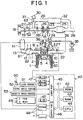
- Fig. 1 shows a 4-stroke compression ignition type internal combustion engine to which the invention has been applied.
- reference numeral 1 denotes an engine body
- reference numeral 2 denotes a cylinder block
- reference numeral 3 denotes a cylinder head
- reference numeral 4 denotes a piston
- reference numeral 5 denotes a combustion chamber
- reference numeral 6 denotes an electrically controlled type fuel injection valve
- reference numeral 7 denotes an intake valve
- reference numeral 8 denotes an intake port
- reference numeral 9 denotes an exhaust valve
- reference numeral 10 denotes an exhaust port, respectively.
- the intake port 8 is connected to a surge tank 12 via a corresponding intake branch pipe 11, and the surge tank 12 is connected to a supercharger, for example, an outlet portion of a compressor 16 of an exhaust turbo charger 15 via an intake duct 13 and an inter-cooler 14.
- An inlet portion of the compressor 16 is connected to an air cleaner 18 via an air intake pipe 17, and a throttle valve 20 driven by a stepper motor 19 is disposed within the air intake pipe 17.
- a mass flow rate detecting device 21 for detecting a mass flow rate of the intake air is disposed within the air intake pipe 17 located upstream the throttle valve 20.
- the exhaust port 10 is connected to an inlet portion of an exhaust turbine 23 of the exhaust turbo charger 15 via an exhaust manifold 22, and an outlet portion of the exhaust turbine 23 is connected to a catalytic converter 26 containing a catalyst 25 having an oxidation function there within via an exhaust pipe 24.
- An air fuel ratio sensor 27 is disposed within the exhaust manifold 22.
- An exhaust pipe 28 connected to an outlet portion of the catalytic converter 26 and the air intake pipe 17 disposed downstream the throttle valve 20 are connected to each other via an EGR passage 29, and an EGR control valve 31 driven by a stepper motor 30 is arranged within the EGR passage 29. Furthermore, an inter-cooler 32 for cooling an EGR gas flowing within the EGR passage 29 is arranged within the EGR passage 29. In the embodiment shown in Fig. 1, an engine cooling water is introduced into the inter cooler 32, and the EGR gas is cooled by the engine cooling water.
- the structure of the engine can be modified such that the exhaust pipe 28 connected to the outlet portion of the catalytic converter 26 and the air intake pipe 17 disposed downstream the throttle valve 20 are not connected to each other via the EGR passage 29, and a catalytic converter containing a catalyst having an oxidation function, such as an oxidation catalyst, a three way catalyst or an nitrogen oxides NOx absorbing agent there within is provided in the EGR passage 29 so as to connect to the exhaust manifold 22 disposed upstream the exhaust turbine 23. Accordingly, a part of the exhaust gas discharged within the exhaust manifold 22 is supplied to the air intake pipe 17 via the EGR passage 29 and the remaining exhaust gas is supplied to the exhaust turbine 23.
- a catalytic converter containing a catalyst having an oxidation function such as an oxidation catalyst, a three way catalyst or an nitrogen oxides NOx absorbing agent there within is provided in the EGR passage 29 so as to connect to the exhaust manifold 22 disposed upstream the exhaust turbine 23.
- a pressure of the EGR gas becomes higher than that of the embodiment shown in Fig. 1, however, a capacity for supercharging becomes low.
- an unburned hydrocarbon HC and soluble organic fractions SOF are purified by the catalyst, so that the EGR gas hardly containing the unburned hydrocarbon HC and the soluble organic fractions SOF is supplied into the air intake pipe 17.
- the structure of the engine can be modified such that a water cooling type EGR cooler and an air cooling type EGR cooler are arranged within the EGR passage 29. Accordingly, the EGR gas flowing within the EGR passage 29 from the side of the engine exhaust passage to the side of the engine intake passage is cooled to a predetermined temperature and net can then be cooled by the water cooling type EGR cooler.
- the fuel injection valve 6 is connected to a fuel reservoir, known as a common rail 34, via a fuel supply pipe 33.
- Fuel is supplied into the common rail 34 from an electrically controlled fuel pump 35 in which a discharge amount is variable, and the fuel supplied into the common rail 34 is supplied to the fuel injection valve 6 via the fuel supply pipe 33.
- a fuel pressure sensor 36 for detecting a fuel pressure within the common rail 34 is mounted thereto, a discharge amount of the fuel pump 35 can be controlled such that the fuel pressure within the common rail 34 reaches a target fuel pressure on the basis of an output signal of the fuel pressure sensor 36.
- An electronic control unit 40 is constituted by a digital computer and is provided with a read only memory (ROM) 42, a random access memory (RAM) 43, a microprocessor (CPU) 44, an input port 45 and an output port 46 mutually connected by a two way bus 41.
- ROM read only memory
- RAM random access memory
- CPU microprocessor
- a water temperature sensor 60 for detecting a temperature of an engine cooling water is arranged in the engine main body 1, and an output signal of the water temperature sensor 60 is input to the input port 45 via a corresponding A/D converter 47.
- a combustion pressure sensor 37 for detecting a pressure within the combustion chamber 5 is arranged within the combustion chamber 5, and an output signal of the combustion pressure sensor 37 is connected to an input terminal I of a peak hold circuit 49.
- An output terminal O of the peak hold circuit 49 is input to the input port 45 via the corresponding A/D converter 47.
- a pressure sensor 38 for detecting an absolute pressure within the air intake pipe 17 is mounted within the air intake pipe 17 disposed downstream the throttle valve 20, and an output signal of the pressure sensor 38 is input to the input port 45 via the corresponding A/D converter 47.
- a pressure sensor 61 for detecting an absolute pressure within the surge tank 12 and a temperature sensor 62 for detecting a temperature of a mixed gas between the intake air and the EGR gas are arranged in the surge tank 12, and output signals of the pressure sensor 61 and the temperature sensor 62 are respectively input to the input port 45 via the corresponding A/D converters 47.
- a humidity sensor 63 for detecting a humidity of the intake air is disposed within the air intake pipe 17 located upstream the throttle valve 20, and an output signal of the humidity sensor 63 is input to the input port 45 via the corresponding A/D converter 47.
- An output signal of the fuel pressure sensor 36 is input to the input port 45 via the corresponding A/D converter 47.
- a load sensor 51 for generating an output voltage in proportion to a depression amount L of an accelerator pedal 50 is connected to the accelerator pedal 50, and an output voltage of the load sensor 51 is input to the input port 45 via the corresponding A/D converter 47.
- a crank angle sensor 52 for generating an output pulse at every rotation of the crank shaft, for example, at 30 degrees, is connected to the input port 45.
- the output port 46 is connected to the fuel injection valve 6, the throttle valve controlling stepper motor 19, the EGR control valve controlling stepper motor 30, the fuel pump 35 and a reset input terminal R of the peak hold circuit 49 via the corresponding drive circuit 48.
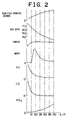
- Fig. 2 is a graph showing an experimental result of the change in an output torque, discharge amount of smoke, hydrocarbon HC, carbon monoxide CO and nitrogen oxides NOx with respect to an air fuel ratio A/F that varies by changing an opening degree of the throttle valve 20 and the EGR rate during operation of the engine in Fig. 1 at a low load.
- the smaller the air fuel ratio A/F the greater the EGR rate.
- the air fuel ratio A/F is equal to or less than a stoichiometric air fuel ratio of approximately 14.6.
- the air fuel ratio A/F is reduced when the EGR rate is increased.
- the air fuel ratio A/F reaches about 30 and the EGR rate is approximately 40 %, the amount of smoke generated starts increasing.
- the EGR rate is further increased such that the air fuel ratio A/F is reduced, the amount of smoke generated sharply increases to a peak amount after which, when further increasing the EGR rate to reduce the air fuel ratio A/F even further, the amount of smoke generated is suddenly reduced.
- the air fuel ratio A/F reaches approximately 15 and the EGR rate is approximately 65 % or greater, the amount of smoke generated is substantially 0. In other words, hardly any soot is generated.
- the amount of nitrogen oxides NOx generated is significantly reduced. Contrarily, the amount of hydrocarbon HC and carbon monoxide CO generated starts to increase at the same time.
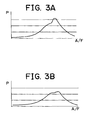
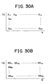
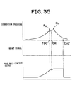
- Fig. 3A shows the change in the combustion pressure P within the combustion chamber 5 when the air fuel ratio A/F reaches approximately 21 where the largest amount of smoke is generated.
- Fig. 3B shows the change in the combustion pressure P within the combustion chamber 5 when the air fuel ratio A/F reaches approximately 18 where the amount of smoke generated is substantially 0.
- the combustion pressure P in Fig. 3B where the amount of smoke generated is substantially 0 is lower than the combustion pressure P in Fig. 3A where the amount of smoke generated is large.
- the hydrocarbon HC is discharged without evolving into soot. That is, a straight chain hydrocarbon or an aromatic hydrocarbon contained in the fuel, as shown in Fig. 4, will thermally decompose when the temperature is increased in a poor oxygen state, thus taking the form of a precursor of the soot.
- the solid soot is produced mainly in the form of an aggregation of carbon atoms. In this case, the actual process of producing the soot is complex and the exact form assumed by the precursor of the soot cannot be clarified.
- the hydrocarbon HC at this time is formed as the precursor of the soot or the hydrocarbon HC in the state preceding the precursor.
- the predetermined temperature is defined by various factors, e.g., kind of the fuel in use, compression ratio, or the air fuel ratio, the predetermined temperature cannot be specified to an exact value.
- the predetermined temperature is related to the amount of nitrogen oxides NOx generated, and can be derived from the amount of nitrogen oxides NOx generated to a predetermined degree. That is, as the EGR rate is increased, the temperature of the fuel and the surrounding gas at a time of combustion is decreased, thus reducing the amount of nitrogen oxides NOx generated.
- the soot is barely generated when the amount of nitrogen oxides NOx generated becomes approximately 10 p.p.m. or less. Accordingly, the aforementioned predetermined temperature substantially coincides with the temperature when the amount of nitrogen oxides NOx generated becomes approximately 10 p.p.m. or less.
- the soot cannot be purified by post-treatment using the catalyst having an oxidation function.
- the precursor of the soot or the hydrocarbon HC in the preceding state can easily be purified by post-treatment using the catalyst having an oxidation function.
- the structure of the combustion system used in the invention basically focuses on discharging the hydrocarbon HC from the combustion chamber 5 as the precursor of the soot or the preceding state without generating the soot within the combustion chamber 5 and then oxidizing the hydrocarbon HC using the catalyst having the oxidation function.
- the evaporated fuel immediately reacts with the oxygen in the air and is burned.
- the temperature of the air apart from the fuel is not increased, rather only the temperature around the fuel is substantially increased.
- the air apart from the fuel hardly perform an endothermic activity with respect to the combustion heat in the fuel.
- the combustion temperature is locally increased to a substantially high value, an unburned hydrocarbon HC subjected to the combustion heat produces the soot.
- the condition differs from the above case.
- the evaporated fuel diffuses and reacts with the oxygen contained in the inert gas of the mixture and is burned. Since the combustion heat is absorbed into the peripheral inert gas, the combustion temperature is not increased, thus keeping the combustion temperature at a relatively low level. Accordingly, the inert gas plays an important role in restricting the combustion temperature. The endothermic function of the inert gas, thus, makes it possible to keep the combustion temperature relatively low.
- Fig. 5 is a graph which shows a relationship between the EGR rate and the amount of smoke generated when changing the cooling degree of the EGR gas as the inert gas. That is, a curve A is derived from keeping the EGR gas temperature to approximately 90°C by forcibly cooling the EGR gas, a curve B is derived from cooling the EGR gas by a compact cooling apparatus, and a curve C is derived when the EGR gas is not forcibly cooled.
- the amount of soot generated reaches a peak amount when the EGR rate is slightly less than 50 %. As such, substantially no soot is generated if the EGR rate is set to approximately 55 % or greater. Contrarily, as shown by the curve B, the amount of soot generated reaches a peak when the EGR rate is slightly higher than 50 %. In this case, substantially no soot is generated if the EGR rate is set to approximately 65 % or greater.
- the amount of soot generated reaches a peak when the EGR rate is approximately 55 %. In this case, substantially no soot is generated if the EGR rate is set to approximately 70 % or greater.
- Fig. 5 shows the amount of smoke generated at a relatively high engine load.
- the EGR rate at which the amount of soot generated reaches its peak is slightly reduced, and a lower limit of the EGR rate at which substantially no soot is generated is slightly reduced as well.
- the lower limit of the EGR rate at which substantially no soot is generated may vary depending on the cooling degree of the EGR gas or the engine load, for example.
- Fig. 6 is a graph showing the relationship between an amount of injected fuel and an amount of a gas mixture.
- the graph in Fig. 6 shows the relationship of the mixture of air and EGR gas as the inert gas required to decrease the temperature of the fuel and surrounding gas during combustion to lower the temperature at which the soot is generated, a rate of the air to the mixture, and a rate of the EGR gas to the mixture gas.
- an ordinate represents a total amount of intake gas introduced into the combustion chamber 5
- a chain line Y shows a total amount of intake gas capable of being introduced within the combustion chamber 5 when supercharging is not performed.
- the other ordinate of Fig. 6 represents a required load.
- the rate of the air that is, the air content in the mixture represents the amount of air required to completely burn the injected fuel. That is, the ratio between the amount of air and the amount of injection fuel corresponds to the stoichiometric air fuel ratio.
- the rate of the EGR gas that is, the amount of EGR gas in the mixture gas represents the minimum amount of EGR gas required to establish the temperature of the fuel and the surrounding gas during burning of the injected fuel to be lower than the temperature at which the soot is generated.
- the amount of EGR gas is substantially equal to or greater than 55 % relative to the EGR rate.
- the amount of EGR gas shown in Fig. 6 is equal to or greater than 70 %.
- the temperature of the fuel and the surrounding gas becomes lower than the temperature at which the soot is generated, thus generating substantially no soot.
- the amount of nitrogen oxides NOx generated at this time results in a significantly small amount of soot, i.e., approximately 10 p.p.m. or less.
- the amount of heat generated when the fuel is burned is increased as the amount of fuel injection is increased, the amount of heat absorbed by the EGR gas has to be increased so as to maintain the temperature of the fuel and the surrounding gas to be lower than the temperature at which the soot is generated. Accordingly, as shown in Fig. 6, the amount of EGR gas should be increased along with the increase in the injection fuel amount. That is, the amount of EGR gas should be increased as the required load is increased.
- the upper limit of the total amount of intake gas X is defined by the chain line Y. Therefore, as shown in Fig. 6, when the required load is larger than L 0 , the air fuel ratio cannot be maintained to the stoichiometric air fuel ratio as the required load becomes higher unless the EGR gas rate is reduced. In other words, when trying to maintain the air fuel ratio to the stoichiometric value in the region where the desired load is larger than L 0 when no supercharging is performed, the EGR rate is reduced as the required load becomes high, and accordingly, in the area at the desired load larger than L 0 , it is impossible to maintain the temperature of the fuel and the surrounding gas to be lower than the temperature at which the soot is generated.
- the EGR control valve 31 when setting the EGR rate to a level substantially equal to or more than 55 % in the region where the required load is higher than L 0 , the EGR control valve 31 is fully opened and the throttle valve 20 is slightly closed.
- Fig. 6 shows the case where the fuel is burned at the stoichiometric air fuel ratio.
- the air amount to be less than the value shown in Fig. 6, that is, setting the air fuel ratio to a rich state
- the amount of air to be more than the value shown in Fig. 6, that is, setting an average value of the air fuel ratio to be in the lean state from 17 to 18, it is possible to restrict the amount of nitrogen oxides NOx generated to approximately 10 p.p.m. or less while preventing generation of the soot.
- the air fuel ratio when the air fuel ratio is set to the rich state, the amount of fuel becomes excessive. However, since the combustion temperature is restricted to be low, the excessive fuel does not generate soot, resulting in no generation of soot. At the same time, only a small amount of nitrogen oxides NOx is generated. Meanwhile, when the average air fuel ratio is in a lean state, or even when the air fuel ratio is stoichiometric, a high combustion temperature may lead to production of a small amount of soot. However, in accordance with the invention, as the combustion temperature is kept low, no soot is generated. Additionally the amount of nitrogen oxides NOx is substantially small.
- the air fuel ratio which may be rich, lean, or stoichiometric. Accordingly, it is preferable to set the average air fuel ratio to a lean value for improving fuel consumption.
- the temperature of the fuel and the surrounding gas during combustion in the combustion chamber can be restricted to be lower than the temperature at which the hydrocarbon HC growth is interrupted only when the engine is operated at a middle or low load where the amount of heat generated by the combustion is relatively small. Accordingly, in the first embodiment of the invention, during the middle or low load engine operation, the temperature of the fuel and the surrounding gas during combustion is limited to be substantially equal to or less than the temperature at which the growth of the hydrocarbon HC is interrupted such that the first combustion, that is, the low temperature combustion is conducted. Meanwhile, during the high load engine operation, the second combustion, that is, the conventional combustion is conducted.
- the first combustion that is, the low temperature combustion means a combustion in which the amount of the inert gas within the combustion chamber is greater than that of the inert gas at a time when the amount of soot generated reaches the peak, thus generating substantially no soot, as is apparent from the above explanation.
- the second combustion that is, the conventional combustion means a combustion in which the amount of the inert gas within the combustion chamber is smaller than the amount of the inert gas at a time when the amount of soot generated reaches the peak amount.
- Figs. 7A and 7B the ordinate TQ indicates a required torque and the abscissas N indicates an engine speed.
- Fig. 7B depicts a first operation area I where the low temperature combustion is performed at a substantially stoichiometric or lean air fuel ratio, and a second operation area II where the conventional combustion has to be conducted because the low temperature combustion cannot be accomplished at the substantially stoichiometric or lean air fuel ratio.
- X(N) represents a first boundary between the first operation area I where the low temperature combustion is performed and the second operation area II and Y(N) represents a second boundary between the first operation area I and the second operation area II.
- the transition of the operation area from the first operation area I to the second operation area II is determined on the basis of the first boundary X(N), and the transition of the operation area from the second operation area II to the first operation area I is determined on the basis of the second boundary Y(N).
- two boundaries including the first boundary X(N) and the second boundary Y(N), which is closer to the lower load compared with the first boundary X(N), are provided for the following two reasons.
- a third or load limit operation area Z where low temperature combustion can be performed when the air fuel ratio is made significantly rich, such as, for example, when the air fuel ratio is made smaller than 13.5 %.
- a high load side limit Z1(N) and a low load side limit Z2(N) in the third operation area Z are functions of the engine speed N.
- Fig. 7B it can be seen that there is no limit close to the low load side in the first operation area I in which the low temperature combustion can be performed when the air fuel ratio is substantially equal to the theoretical air fuel ratio or in the lean state. Contrarily, the low load side limit Z2(N) of the third operation area Z in which the low temperature combustion can be performed when the air fuel ratio is significantly rich is present in a region where the required torque TQ is negative. Accordingly, it is understood that the low load side limit Z2(N) of the third operation area Z in which the low temperature combustion can be performed goes to the high load side as the air fuel ratio becomes smaller.
- the high load side limit Z1(N) of the third operation area Z where the low temperature combustion can be performed at substantially rich air fuel ratio is at the high load side in comparison with the high load side limit X(N) of the first operation area I where the low temperature combustion can be performed at substantially the stoichioimetric or lean air fuel ratio. Accordingly, it is understood that the third operation area Z where the low temperature combustion can be performed goes to the high load side as the air fuel ratio becomes smaller.
- the low temperature combustion can be performed irrespective of whether the air fuel ratio is in a rich state or a lean state, as mentioned above.
- the air fuel ratio is set to a significantly rich state
- a misfire is generated.
- effective low temperature combustion cannot be performed. That is, even when the fuel injection amount is significantly small, the fuel is positively burned in the presence of a sufficient amount of air around the fuel particles as long as the air fuel ratio is set to the lean state.
- the air fuel ratio is set to a significantly rich state, a sufficient amount of air does not exist around the fuel particles, thus failing to burn the fuel positively. Therefore, when the fuel injection amount is significantly small, the temperature and pressure during combustion are not sufficiently increased, resulting in the misfire.
- the area where the required torque TQ is negative indicates the deceleration operation time, wherein the amount of fuel injection is extremely small. Accordingly, the low load side limit Z2(N) of the third operation area Z is in the region where the required torque TQ is negative.
- the high side load limit Z1(N) approaches the high load side closer than the first boundary X(N).
- An oxidation catalyst, a three-way catalyst or an nitrogen oxides NOx absorbent can be used as the catalyst 25.
- the nitrogen oxides NOx absorbent absorbs nitrogen oxides NOx when the average air fuel ratio within the combustion chamber 5 is in the lean state, and desorbs nitrogen oxides NOx when the average air fuel ratio within the combustion chamber 5 is in the rich state.
- the nitrogen oxides NOx absorbent is formed of a carrier, such as, for example, an alumina on which a noble metal such as platinum Pt and at least one element selected from an alkaline metal (potassium K, sodium Na, lithium Li, cesium Cs or the like), an alkaline earth metal (barium Ba, calcium Ca, or the like), and a rare earth metal (lanthanum La, yttrium Y, or the like) are carried.
- a carrier such as, for example, an alumina on which a noble metal such as platinum Pt and at least one element selected from an alkaline metal (potassium K, sodium Na, lithium Li, cesium Cs or the like), an alkaline earth metal (barium Ba, calcium Ca, or the like), and a rare earth metal (lanthanum La, yttrium Y, or the like) are carried.
- a carrier such as, for example, an alumina on which a noble metal such as platinum Pt and at least one element selected from an alkaline metal
- the three-way catalyst and the nitrogen oxides NOx absorbent have the oxidation function. Therefore, the three-way catalyst and the nitrogen oxides NOx absorbent can also be used as the catalyst 25.
- Fig. 8 shows a relation among an opening degree of the throttle valve 20 with respect to the required torque TQ, an opening degree of the EGR control valve 31, an EGR rate, an air fuel ratio, an injection timing, and an injection amount.
- the opening degree of the throttle valve 20 is gradually increased from a nearly full close state to about 2/3 of the opening degree as the required torque TQ is increased.
- the opening degree of the EGR control valve 31 is gradually increased from a nearly full close state to a full open state as the required torque TQ is increased.
- the EGR rate is set to substantially 70 % in the first operation area I, while the air fuel ratio is set to a slight lean state.
- the opening degree of the throttle valve 20 and the opening degree of the EGR control valve 31 are controlled such that the EGR rate becomes approximately 70 % and the air fuel ratio is in the slight lean state.
- fuel injection is performed prior to compression at a top dead center TDC.
- an injection start timing ⁇ S is delayed as the required load L becomes high, and an injection end timing ⁇ E is also delayed as the injection start timing ⁇ S is delayed.
- the throttle valve 20 and EGR control valve 31 are simultaneously nearly in the full close state.
- a pressure within the combustion chamber 5 at the beginning of the compression becomes low, thus reducing the compression pressure.
- compression work executed by the piston 4 is reduced to decrease vibration of the engine main body 1. That is, during idling operation, in order to restrict the vibration of the engine main body 1, the throttle valve 20 is closed nearly to the full close state.
- the operation area of the engine shifts from the first operation area I to the second operation area II, and the throttle valve 20 is increased stepwise from about 2/3 of the opening degree to the full open state.
- the EGR rate is decreased stepwise from approximately 70 % to 40 % or less, thereby increasing the air fuel ratio. That is, as the EGR rate skips over the EGR rate range (Fig. 5) where a large amount of smoke is generated, the generation of such smoke can be prevented when the operation area of the engine shifts from the first operation area I to the second operation area II.
- the second combustion that is, the conventional combustion is performed.
- the aforementioned combustion generates small amounts of soot and nitrogen oxides NOx, however, the heat efficiency is higher than that of the low temperature combustion, or first combustion.
- the injection amount is decreased stepwise.
- the throttle valve 20 is kept in the full open state with a few exceptions, and the opening degree of the EGR control valve 31 is gradually reduced as the required torque TQ becomes high.
- the EGR rate becomes low as the required torque TQ becomes high, and the air fuel ratio becomes small as the required torque TQ becomes high.
- the air fuel ratio is set to the lean air fuel ratio even when the required torque TQ becomes high.
- the injection start timing ⁇ S is set near the compression top dead center TDC.
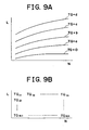
- Fig. 9A is a graph showing a relationship between the required torque TQ relative to the depression amount L of the acceleration pedal 50 and the engine speed N.
- Each curve of Fig. 9A represents a uniform torque curve.
- the required torque TQ corresponding to the depression amount L of the acceleration pedal 50 and the engine speed N is calculated first from the map shown in Fig. 9B, and the target air fuel ratio and the like can be calculated on the basis of the required torque TQ.
- the high load side limit of the first operation area I where the low temperature combustion can be performed varies with the temperature of the gas within the combustion chamber 5, the temperature of the inner wall surface of the cylinder and the like at the beginning of compression. That is, when the required torque TQ becomes high and the heat generated by the combustion is increased, the temperature of the fuel and the surrounding gas thereof during combustion becomes high, thus failing to perform the low temperature combustion. Contrarily, when the gas temperature TG within the combustion chamber 5 at the beginning of the compression becomes low, the temperature of the gas within the combustion chamber 5 immediately before the start of combustion becomes low so that the temperature of the fuel and the surrounding gas during combustion also becomes low.
- the gas temperature TG within the combustion chamber 5 at the beginning of the compression becomes low, the temperature of the fuel and the surrounding gas during combustion is not increased even when the heat generated by the combustion is increased, that is, the required torque TQ becomes high, performing the low temperature combustion.
- the gas temperature TG within the combustion chamber 5 at the beginning of compression becomes lower, the first operation area I where the low temperature combustion can be performed is expanded toward the high load side.
- the pressure within the intake passage such as, for example, the surge tank 12 becomes lower
- the compression pressure within the combustion chamber 5 becomes low. Accordingly, the temperature of the fuel and the surrounding gas during combustion is lowered.
- the first operation area I where the low temperature combustion can be performed is expanded toward the high load side.
- the humidity of the intake air becomes higher
- an endothermic amount of moisture contained in the intake air is increased.
- the temperature of the fuel and the surrounding gas during combustion is lowered. Accordingly, as the humidity in the intake air becomes higher, the first operation area I where the low temperature combustion can be performed is expanded toward the high load side.
- the first boundary when the gas temperature TG within the combustion chamber 5 at the beginning of the compression becomes low, the first boundary is shifted from Xo(N) to X(N), as shown in Fig. 10.
- the temperature difference (TW - TG) is reduced, the first boundary is shifted from Xo(N) to X(N).
- the first boundary when the pressure PM within the surge tank 12 is reduced, the first boundary also shifts from Xo(N) to X(N), and when a humidity DF in the intake air becomes high, the first boundary also is shifted from Xo(N) to X(N).
- the Xo(N) indicates the reference first boundary.
- K(T) 2 is a function of the temperature difference (TW - TG), as shown in Fig. 11B. A value of K(T) 2 becomes greater as the temperature difference (TW - TG) becomes smaller. Still further, K(T) 3 is a function of a pressure PM within the surge tank 12, as shown in Fig. 11C. A value of K(T) 3 becomes greater as the pressure PM within the surge tank 12 becomes lower. K(T) 4 is a function of a humidity DF, as shown in Fig. 11D. A value of K(T) 4 becomes greater as the humidity DF becomes higher. Looking at Figs.
- T1 is a reference temperature
- T2 is a reference temperature difference
- PM3 is a reference pressure
- DF4 is a reference humidity
- K(N) is a function of the engine speed N, as shown in Fig. 11E.
- a value of K(N) becomes smaller as the engine speed N becomes higher. That is, when the gas temperature TG within the combustion chamber at the beginning of the compression becomes lower than the standard temperature T1, the first boundary X(N) shifts to the high load side with respect to Xo(N) as the gas temperature TG within the combustion chamber 5 at the beginning of the compression becomes lower. When the temperature difference (TW - TG) becomes lower than the standard temperature difference T2, the first boundary X(N) shifts to the high load side with respect to Xo(N) as the temperature difference (TW - TG) becomes smaller.
- the first boundary X(N) shifts to the high load side with respect to Xo(N) as the pressure within the surge tank 12 becomes lower.
- the humidity DF becomes greater than the reference humidity DF4
- the first boundary X(N) shifts to the high load side with respect to Xo(N) as the humidity DF becomes higher.
- a moving amount of X(N) with respect to Xo(N) becomes smaller as the engine speed N becomes higher.
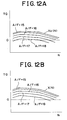
- Fig. 12A shows an air fuel ratio A/F in the first operation area I where the first boundary is the reference first boundary Xo(N).
- Each of the air fuel ratios between those curves is prorated.
- the air fuel ratio becomes lean in the first operation area I, and further leaner as the required load L is lowered.
- the air fuel ratio A/F is set to a greater value as the required load L becomes low. As the air fuel ratio A/F becomes greater, the fuel consumption is improved. Therefore in the first embodiment, the air fuel ratio A/F is set to a greater value as the required load L is lowered so as to make the air fuel ratio as lean as possible.
- Fig. 12B shows an air fuel ratio A/F in the first operation area I where the first boundary is X(N), as shown in Fig. 10.
- the air fuel ratio A/F at the same required load L and the same engine speed N becomes greater. That is, when the first operation area I is expanded toward the high load side, the operation area for generating substantially no soot or nitrogen oxides NOx is expanded, and fuel consumption is improved as well.
- the target air fuel ratio in the first operation area I when the first boundary X(N) changes is in a wide range.
- the target air fuel ratio in the first operation area I with respect to various values of K(T) has been previously stored within the ROM 42 in the form of a map as a function of the required torque TQ and the engine speed N, as shown in Figs. 13A to 13D. That is, Fig. 13A shows a target air fuel ratio AFKT1 when a value of K(T) is KT1.
- Fig. 13B shows a target air fuel ratio AFKT2 when a value of K(T) is KT2.
- Fig. 13C shows a target air fuel ratio AFKT3 when a value of K(T) is KT3.
- Fig. 13D shows a target air fuel ratio AFKT4 when a value of K(T) is KT4.
- the target opening degree of the throttle valve 20 necessary for setting the air fuel ratio to the target air fuel ratio has been previously stored within the ROM 42 in the form of a map as a function of the required torque TQ and the engine speed N as shown in Figs. 14A to 14D.
- the target opening degree of the EGR control valve 31 necessary for setting the air fuel ratio to the target air fuel ratio has been previously stored within the ROM 42 in the form of a map as a function of the required torque TQ and the engine speed N, as shown in Figs. 15A to 15D.
- Fig. 14A shows a target opening degree ST15 of the throttle valve 20 when the air fuel ratio is 15, and Fig. 15A shows a target opening degree SE15 of the EGR control valve 31 when the air fuel ratio is 15.
- Fig. 14B shows a target opening degree ST16 of the throttle valve 20 when the air fuel ratio is 16, and Fig. 15B shows a target opening degree SE16 of the EGR control valve 31 when the air fuel ratio is 16.
- Fig. 14C shows a target opening degree ST17 of the throttle valve 20 when the air fuel ratio is 17, and Fig. 15C shows a target opening degree SE17 of the EGR control valve 31 when the air fuel ratio is 17.
- Fig. 14D shows a target opening degree ST18 of the throttle valve 20 when the air fuel ratio is 18, and Fig. 15D shows a target opening degree SE18 of the EGR control valve 31 when the air fuel ratio is 18.
- a target opening degree ST of the throttle valve 20 necessary for setting the air fuel ratio to the target air fuel ratio has been previously stored within the ROM 42 as a function of the required torque TQ and the engine speed N in the form of a map as shown in Fig. 17A.
- a target opening degree SE of the EGR control valve 31 necessary for setting the air fuel ratio to the target air fuel ratio has been previously stored within the ROM 42 as a function of the required torque TQ and the engine speed N in the form of a map, as shown in Fig. 17B.
- the third operation area Z where low temperature combustion can be performed at a substantially rich air fuel ratio varies with the gas temperature TG within the combustion chamber 5 at the beginning of the compression, the temperature difference (TW - TG) between the cylinder inner wall temperature TW and the gas temperature TG, the pressure PM within the surge tank 12 and the humidity DF in the suction air.
- the third operation area Z shifts toward the high load side, like the first operation area I, as the temperature of the fuel and the surrounding gas during the combustion is lowered.
- a high load side limit Z1(N) and a low load side limit Z2(N) are both shifted toward the high load side when the temperature of the fuel and the surrounding gas during combustion becomes lower than that of the reference cases.
- the third operation area Z is also shifted to the high load side.
- the high load side limit Z1(N) and the low load side limit Z2(N) can be derived from the following equations using respective values K(T) 1 , K(T) 2 , K(T) 3 , K(T) 4 and K(N).
- Z1(N) Z1 o (N)+C2 ⁇ K(T) ⁇ K(N)
- Z2(N) Z2 o (N)+C3 ⁇ K(T) ⁇ K(N)
- K(T) K(T) 1 +K(T) 2 +K(T) 3 +K(T) 4 where C2 and C3 are constants.
- the high load side limit Z1(N) and the low load side limit Z2(N) respectively shift toward the high load side relative to Z1 o (N) and Z2 o (N) as the gas temperature TG within the combustion chamber 5 at the beginning of compression is lowered.
- the temperature difference (TW - TG) becomes lower than the reference temperature difference T 2 (Fig. 11)
- the high load side limit Z1(N) and the low load side limit Z2(N) respectively shift toward the high load side relative to Z1 o (N) and Z2 o (N) as the temperature difference (TW - TG) becomes is lowered.
- the high load side limit Z1(N) and the low load side limit Z2(N) respectively shift toward the high load side relative to Z1 o (N) and Z2 o (N) as the pressure PM within the surge tank 12 is lowered.
- the humidity DF becomes larger than the reference humidity DF4 (Fig. 11)
- the high load side limit Z1(N) and the low load side limit Z2(N) respectively shift toward the high load side relative to Z1 o (N) and Z2 o (N) as the humidity DF becomes higher.
- an oxidation catalyst, a three-way catalyst and an nitrogen oxides NOx absorbent can be employed as the catalyst 25.
- an oxidation catalyst, a three-way catalyst and an nitrogen oxides NOx absorbent can be employed as the catalyst 25.
- an nitrogen oxides NOx absorbent as the catalyst 25 will be described.
- the ratio between an air and a fuel, such as a hydrocarbon HC, supplied to the engine intake passage, the combustion chamber 5 and the exhaust air passage disposed upstream the nitrogen oxides NOx absorbent is referred to as an air fuel ratio of an inflow exhaust gas to the nitrogen oxides NOx absorbent.
- the nitrogen oxides NOx absorbent absorbs an nitrogen oxides NOx when the air fuel ratio of the flowing exhaust gas is lean and desorbs the absorbed nitrogen oxides NOx when the air fuel ratio of the inflow exhaust gas becomes the stoichiometric or rich air fuel ratio.
- the nitrogen oxides NOx absorbent 25 When positioning the nitrogen oxides NOx absorbent within the engine exhaust passage, the nitrogen oxides NOx absorbent 25 actually performs absorbing and desorbing the nitrogen oxides NOx.
- the absorbing and desorbing operation is performed by the mechanism shown in Figs. 19A and B.
- a platinum Pt and a barium Ba are carried on the carrier.
- the same mechanism can be obtained when using other noble metals, such as alkaline metal, alkaline earth metal, and rare earth metal.
- combustion is normally performed in a state where the air fuel ratio in the combustion chamber 5 is lean.
- a concentration of oxygen O z in the exhaust gas is high, and at this time, the oxygen O 2 is attached to a surface of the platinum Pt in the form of O 2 - or O 2- , as shown in Fig. 19A.
- NOx contained in the inlet exhaust gas reacts with O 2 - or O 2- on the platinum Pt to produce NO 2 (2NO + O 2 2NO 2 ).
- a part of the generated NO 2 is absorbed into the absorbent while being oxidized on the platinum Pt so as to diffuse within the absorbent in the form of nitric acid ion NO 3- , as shown in Fig. 19A, while combining with a barium oxide BaO.
- nitrogen oxides NOx is absorbed into the nitrogen oxides NOx absorbent.
- NO 2 is generated on the surface of the platinum Pt, and as long as the nitrogen oxides NOx absorbing capacity of the absorbent is not saturated, NO 2 is absorbed within the absorbent, so that the nitric acid ion NO 3 - is produced.
- nitrogen oxides NOx is desorbed from the nitrogen oxides NOx absorbent.
- nitrogen oxides NOx is gradually desorbed from the nitrogen oxides NOx absorbent, requiring a longer time to have all the nitrogen oxides NOx absorbed in the nitrogen oxides NOx absorbent desorbed therefrom
- the nitrogen oxides NOx absorbed capacity of the nitrogen oxides NOx absorbent is limited, it is necessary to have nitrogen oxides NOx desorbed from the nitrogen oxides NOx absorbent before the nitrogen oxides NOx absorbing capacity of the nitrogen oxides NOx absorbent is saturated. For this, it is necessary to estimate the nitrogen oxides NOx amount absorbed in the nitrogen oxides NOx absorbent. Then, in accordance with the first embodiment of the invention, the nitrogen oxides NOx absorbed amount ⁇ NOX in the nitrogen oxides NOx absorbent is estimated by previously determining an amount of nitrogen oxides NOx absorbed A per a unit time when the first combustion is performed as a function of the required torque TQ and the engine speed N in the form of a map shown in Fig.
- the structure can be made to have nitrogen oxides NOx desorbed from the nitrogen oxides NOx absorbent when the nitrogen oxides NOx absorbed amount ⁇ NOX exceeds a predetermined allowable maximum value.
- an allowable maximum value MAX1 is set to about 30 % of the maximum nitrogen oxides NOx absorbing amount that can be absorbed by the nitrogen oxides NOx absorbent
- the allowable maximum value MAX2 is set to about 80 % of the maximum absorbing amount that can be absorbed by the nitrogen oxides NOx absorbent.
- the air fuel ratio is set to rich such that the nitrogen oxides NOx is desorbed from the nitrogen oxides NOx absorbent.
- the air fuel ration is set to rich such that the nitrogen oxides NOx is desorbed from the nitrogen oxides NOx absorbent at a time of being switched from the second combustion to the first combustion, such as, for example, during a decelerating operation, and when the nitrogen oxides NOx absorbed amount ⁇ NOX exceeds the allowable maximum value MAX2 during the second combustion, an additional fuel is injected at a later half of an expansion stroke or during an exhaust stroke so as to have nitrogen oxides NOx desorbed from the nitrogen oxides NOx absorbent.
- a period X indicates that the required torque TQ is lower than the first boundary X(N) and the first combustion is performed.
- the air fuel ratio is slightly leaner than the stoichiometric air fuel ratio.
- the nitrogen oxides NOx absorbed amount ⁇ NOX increases at a substantially slow rate.
- the air fuel ratio A/F is temporarily set to rich, whereby the nitrogen oxides NOx absorbent desorbs the nitrogen oxides NOx. At this time, the nitrogen oxides NOx absorbed amount ⁇ NOX is set to 0.
- the operation is switched from the first combustion to the second combustion.
- the required torque TQ exceeds the first boundary X(N) at a time t1
- the first combustion is switched to the second combustion.
- the air fuel ratio A/F becomes significantly lean.
- the generation amount of nitrogen oxides NOx is more than that obtained during the first combustion. Accordingly, during the second combustion, the nitrogen oxides NOx absorbed amount ⁇ NOX is increased at a relatively high rate.
- the air fuel ratio A/F cannot be set to rich during the second combustion. Accordingly, even when the nitrogen oxides NOx absorbed amount ⁇ NOX exceeds the allowable maximum value MAX1 during the second combustion, as shown in Fig. 21, the air fuel ratio A/F cannot be set to rich for the purpose of having the nitrogen oxides NOx desorbed from the nitrogen oxides NOx absorbent. In this case, after the required torque TQ is lower than the second boundary Y(N) so as to switch the combustion from the second to the first combustion, the air fuel ratio A/F is temporarily set to rich so that the nitrogen oxides NOx absorbent desorbs the nitrogen oxides NOx.
- the time t2 in Fig. 21 indicates that deceleration is performed and the combustion is switched from the first combustion to the second combustion.
- the required torque TQ becomes negative.
- whether the air fuel ratio can be set to rich is governed by the position of the low load side limit Z2(N) of the third operation area Z, as is understood from Fig. 18.
- the air fuel ratio A/F is temporarily set to rich such that the nitrogen oxides NOx absorbent 25 desorbs the nitrogen oxides NOx when switching from the second combustion to the first combustion.
- the second combustion is continued for a predetermined time.
- the nitrogen oxides NOx absorbed amount ⁇ NOX exceeds the allowable maximum value MAX1 and further exceeds the allowable maximum value MAX2 at a time t4, at which point additional fuel is injected at the later half of the expansion stroke or during the exhaust stroke.
- the air fuel ratio of the exhaust gas flowing into the nitrogen oxides NOx absorbent is set to rich.
- the additional fuel injected at the later half of the expansion stroke or during the exhaust stroke is not used for generating the engine output. Therefore, it is preferable to reduce the chance for injecting the additional fuel as little as possible. Accordingly, when the nitrogen oxides NOx absorbed amount ⁇ NOX exceeds the allowable maximum value MAX1 during the second combustion, it is structured to temporarily set the air fuel ratio A/F to rich when switching from the second to the first combustion such that the additional fuel is injected only for the special occasion where the nitrogen oxides NOx absorbed amount ⁇ NOX exceeds the allowable maximum value MAX2.
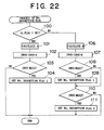
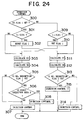
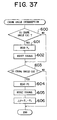
- Fig. 22 shows a process routine of a nitrogen oxides NOx desorption flag set at a time when nitrogen oxides NOx should be desorbed from the nitrogen oxides NOx absorbent.
- the routine is executed by an interruption per a fixed time.
- step 100 it is determined whether a flag I showing that the operation area of the engine is in the first operation area I.
- the flag I is set, that is, the operation area of the engine is in the first operation area I
- the process goes to step 101 where the nitrogen oxides NOx absorbed amount A per a unit time is calculated from a map shown in Fig. 20A.
- step 102 the nitrogen oxides NOx absorbed amount is added to the nitrogen oxides NOx absorbed amount ⁇ NOX.
- step 103 it is determined whether the nitrogen oxides NOx absorbed amount ⁇ NOX exceeds the allowable maximum value MAX1. if ⁇ NOX > MAX1, the process goes to step 104 where the nitrogen oxides NOx desorption flag 1 indicating that the nitrogen oxides NOx should be desorbed when the first combustion is performed is set.
- step 100 when it is determined that the flag I is set, that is, when the operation area of the engine is in the second operation area II, the process goes to step 106.
- the nitrogen oxides NOx absorbed amount B per a unit time is calculated from a map shown in Fig. 20B.
- step 107 the nitrogen oxides NOx absorbed amount B is added to the nitrogen oxides NOx absorbed amount ⁇ NOX.
- step 108 it is determined whether the nitrogen oxides NOx absorbed amount ⁇ NOX exceeds the allowable maximum value MAX1. if ⁇ NOX > MAX1, the process goes to step 109 where the nitrogen oxides NOx desorption flag 1 indicating that nitrogen oxides NOx should be desorbed when the first combustion is performed is set.
- step 110 it is determined whether the nitrogen oxides NOx absorbed amount ⁇ NOX exceeds the allowable maximum value MAX2. if ⁇ NOX > MAX2, the process proceeds to step 111 where the nitrogen oxides NOx desorption flag 2 indicating that nitrogen oxides NOx should be desorbed at the latter half of the expansion stroke or the exhaust stroke is set.
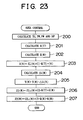
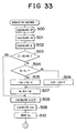
- Fig. 23 shows a process routine for controlling a low temperature combustion area, that is, the first operation area I and the third operation area Z.
- the gas temperature TG within the combustion chamber 5 at the beginning of the compression, the cylinder inner wall temperature TW, the pressure P within the surge tank 12 and the humidity DF in the intake air are calculated in step 200. Then, a temperature of a gas mixture between the intake air and the EGR gas detected by the temperature sensor 62 is set to the gas temperature TG within the combustion chamber 5 at the beginning of the compression, and an engine cooling water temperature detected by the temperature sensor 60 is set to the cylinder inner wall temperature TW. Further, the pressure PM within the surge tank 12 is detected by the pressure sensor 61, and the humidity DF is detected by the humidity sensor 63.
- step 202 K(N) is calculated from the relationship shown in Fig. 11E on the basis of the engine speed N.
- a value of the first boundary X(N) is calculated on the basis of the following formula by using the value of the previously stored first boundary Xo(N).
- X(N) Xo(N)+C1 ⁇ K(T) ⁇ K(N)
- the low load side limit Z2(N) is calculated from the following formula by using the value of the previously stored low load side limit Z2o(N).
- Z2(N) Z2o(N)+C3 ⁇ K(T) ⁇ K(N)
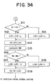
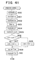
- step 300 it is determined whether a flag I showing that the operation area of the engine is in the first operation area I is set.
- the flag I is set, that is, the operation area of the engine is in the first operation area I
- the process goes to step 301 where it is determined whether the required load L becomes greater than the first boundary X1 (N). If L ⁇ X1 (N), the process goes to step 303 where the low temperature combustion is performed.
- step 303 the target opening degree ST of the throttle valve 20 is calculated from a map shown in Figs. 14A to 14D, and the opening degree of the throttle valve 20 is set to the target opening degree ST.
- step 304 the target opening degree of the EGR control valve 31 is calculated from a map shown in Figs. 15A to 15D, and the opening degree of the EGR control valve 31 is set to the target opening degree SE.
- step 305 it is determined whether the nitrogen oxides NOx desorption flag 1 is set. When the nitrogen oxides NOx desorption flag is not set, the process goes to step 307 where the fuel injection is performed. At this time, the low temperature combustion is performed at the lean air fuel ratio.
- step 305 if in step 305 it is determined that the nitrogen oxides NOx desorption flag 1 is set, the process goes to step 306 where it is determined whether the engine operation state is in the third operation area Z.
- the process goes to the step 307, and the low temperature combustion is performed at the lean air fuel ratio.
- the process goes to step 308, and the air fuel ratio is made rich for a predetermined period. During this period, nitrogen oxides NOx is desorbed from the nitrogen oxides NOx absorbent. Then, the nitrogen oxides NOx desorption flag 1 is reset, and ⁇ NOX is cleared.
- step 301 when it is determined that L > X (N), the process goes to step 302 where the flag I is reset and further goes to step 311 where the second combustion is performed.
- step 311 the target opening degree ST of the throttle valve 20 is calculated from a map shown in Fig. 17A and the opening degree of the throttle valve 20 is set to the target opening degree ST.
- step 312 the target opening degree SE of the EGR control valve 31 is calculated from a map shown in Fig. 17B and the opening degree of the EGR control valve 31 is set to the target opening degree SE.
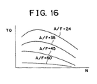
- step 313 it is determined whether the nitrogen oxides NOx desorption flag 2 is set. When the nitrogen oxides NOx desorption flag 2 is not set, the process goes to step 314 where the fuel injection is performed so as to achieve the air fuel ratio shown in Fig. 16. At this time, the second combustion is performed at the lean air fuel ratio.
- step 313 when it is determined that the nitrogen oxides NOx desorption flag 2 is set, the process goes to step 315 where additional fuel is injected for a predetermined period in the latter half of the expansion stroke or during the exhaust stroke. At this time, the air fuel ratio of the exhaust gas flowing into the nitrogen oxides NOx absorbent becomes rich, and during this time, nitrogen oxides NOx is desorbed from the nitrogen oxides NOx absorbent. Then, the nitrogen oxides NOx desorption flags 1 and 2 are reset, and ⁇ NOX is cleared.
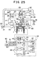
- Fig. 25 shows a second embodiment of the invention having a structure for uniformly distributing the EGR gas to each of the cylinders. An explanation of the structure similar to the engine shown in Fig. 1 will be omitted.
- an exhaust gas temperature sensor 80 for detecting a temperature of an exhaust gas from each of the cylinders is arranged within each of the exhaust manifolds 22 corresponding to each of the cylinders.
- An avenge value of output values of all the exhaust gas temperature sensors 80 is calculated from the output value of each of the exhaust gas temperature sensors 80 corresponding to each of the cylinders. It is determined that the cylinder having a difference between the output value of the exhaust gas temperature sensor 80 and the calculated average value equal to or greater than a predetermined value has a dispersion of the fuel injection amount in comparison with the other cylinders.
- a correction for increasing or reducing the fuel injection period is performed, and it is intended to reduce the dispersion in the fuel injection amount.
- an EGR surge tank 70 for preventing the EGR gas from pulsating and for accurately distributing the EGR gas into the combustion chamber 5 of the respective cylinders is arranged within the EGR passage 29 disposed upstream the joining portion between the intake branch pipe 11 and the EGR passage 29.
- a portion of the EGR passage 29 which is disposed downstream the EGR surge tank 70 and branched into four portions by the EGR surge tank 70 is hereinafter called an EGR branch pipe 71.
- Fig. 26 is schematic diagram illustrating an enlarged view of the intake surge tank 12 and the EGR surge tank 70.
- intake air passing through the throttle valve 20 flows into the intake surge tank 12 via the intake duct 13.
- the intake air is accurately distributed into each of the cylinders by the intake surge tank 12.
- the intake air is then supplied into the combustion chamber 5 in each of the cylinders via each of the intake branch pipes 11.
- the intake air passing through the EGR control valve 31 flows into the EGR surge tank 70 via the EGR passage 29.
- the intake air is them accurately distributed into each of the cylinders by the EGR surge tank 70 and supplied into the combustion chamber 5 in each of the cylinders via each of the EGR branch pipes 71 and the corresponding intake branch pipe 11.
- Fig. 27 is schematic diagram illustrating an enlarged, detailed view of a joining portion between the intake air branch pipe 11 and the EGR branch pipe 71 for a corresponding cylinder.
- the intake air branch pipe 11 corresponding to the cylinder is connected to the cylinder via branched intake ports 72, 73.
- a blow-by discharge port 91 for recirculating a blow-by gas, a fuel gas, such as an evaporation gas, and the like into the intake port 72 so as to discharge into the combustion chamber 5 is arranged within one intake port 73 of the branched intake ports 72, 73.
- the blow-by gas means a gas which is discharged into the crank case from a gap of the piston ring in a compression stroke and an explosion stroke of the engine and reaches the cylinder head 3 via a gap between the inner wall and the outer wall of the cylinder block 2.
- the EGR branch pipe 71 extending from the EGR surge tank 70 joins with one of the branched intake ports 72, 73, i.e., the intake port 72.
- An intake air flow control valve 90 for forming a swirl is arranged within the intake air port, which is not joined with the EGR branch pipe 71, i.e., the intake air port 73, in which the blow-by gas discharge hole 91 is provided, and is arranged upstream of the blow-by gas discharge hole 91.
- a purge line (not shown) for the evaporation gas control system is also connected to the blow-by gas discharge hole 91.
- the EGR surge tank 70 for the EGR gas for distributing the EGR gas into the combustion chamber 5 in each of the cylinders is arranged within the EGR passage 29 disposed upstream the joining portion between the EGR branch pipe 71 and the intake air branch pipe 11. Accordingly, it is possible to accurately distribute the EGR gas flowing into the EGR surge tank 70 into the combustion chamber 5 in each of the cylinders without being influenced by the pulsation of the intake air flowing within the engine intake air passage and the like.
- the intake air surge tank 12 for distributing the intake air into the combustion chamber 5 in each of the cylinders is arranged within the engine intake air passage disposed upstream the joining portion between the intake air branch pipe 11 and the EGR branch pipe 71. Accordingly, it is possible to accurately distribute the intake air flowing into the intake air surge tank 12 into the combustion chamber 5 in each of the cylinders without being influenced by the pulsation of the EGR gas flowing within the EGR passage 29 and the like.
- the EGR control valve 31 for controlling an amount of the EGR gas supplied within the combustion chamber 5 is arranged within the EGR passage 29 disposed upstream the EGR surge tank 70 in an adjacent manner to the EGR surge tank 70. That is, the EGR control valve 31 is arranged within the EGR passage 29 before branching into each of the cylinders and in the portion relatively near each of the cylinders. Accordingly, it is possible to improve a response performance when controlling the EGR gas amount supplied to each of the cylinders.
- the blow-by gas discharge hole 91 is provided within one intake air port 73 among the branched plural intake air ports 72, 73, and the joining portion between the intake air branch pipe 11 and the EGR branch pipe 71 is arranged within the other intake air port 72. That is, the blow-by gas and the EGR gas are not mixed within the intake air port 72 or 73. Accordingly, it is possible to prevent a deposit generated by the mixture of the blow-by gas and the EGR gas from attaching within the intake air port 72 or 73.
- the intake air flow control valve 90 for forming the swirl is arranged within the intake airport 73 having no joining portion between the intake air branch pipe. Accordingly, it is possible to prevent a deposit in the EGR gas from attaching to the intake air flow control valve 90.
- the intake air flow control valve 90 is arranged within the intake air port 73 in which the blow-by gas discharge hole 91 is provided and upstream the blow-by gas discharge pipe 91. Accordingly, it is possible to prevent the deposit in the blow-by gas from attaching to the intake air flow control valve 90.
- FIG. 28A there is shown an injection amount Q in the first operation area I.
- Fig. 28B there is shown a standard injection start timing ⁇ S in the first operation area I.
- the injection amount Q in the first operation area I is previously stored in the ROM 42 in the form of a map as a function of the required torque Q and the engine speed N
- the standard injection start timing S in the first operation area I is also previously stored in the ROM 42 in the form of a map as a function of the required torque TQ and the engine speed N.
- the target opening degree ST of the throttle valve 20 necessary for setting the air fuel ratio to an air fuel ratio corresponding to the engine operation state is previously stored in the ROM 42 in the form of a map as a function of the required torque TQ and the engine speed N, as shown in Fig. 29A.
- the target opening degree SE of the EGR control valve 31 necessary for setting the air fuel ratio to an air fuel ratio corresponding to the engine operation state is previously stored in the ROM 42 in the form of a map as a function of the required torque TQ and the engine speed N, as shown in Fig. 29B.
- the pressure PM0 within the air intake pipe 17 disposed downstream the throttle valve 20 at a time when the air fuel ratio is set to an air fuel ratio corresponding to the engine operation state, for example, the target air fuel ratio A/F shown in Fig. 12, and the EGR rate is set to the target EGR rate corresponding to the engine operation state is previously stored in the ROM 42 in the form of a map as a function of the required torque TQ and the engine speed N, as shown in Fig. 29C.
- Fig. 30A shows an injection amount Q in the second operation area II.
- Fig. 30B shows an injection start timing ⁇ S in the second operation area II.
- the injection amount Q in the second operation area II is previously stored in the ROM 42 in the form of a map as a function of the required torque TQ and the engine speed N.
- the injection start timing ⁇ S in the second operation area II is previously stored in the ROM 42 in the form of a map as a function of the required torque TQ and the engine speed N.
- the target opening degree ST of the throttle valve 20 necessary for setting the air fuel ratio to the target air fuel ratio shown in Fig. 16 is previously stored in the ROM 42 in the form of a map as a function of the required torque TQ and the engine speed N, as shown in Fig. 31A.
- the target opening degree SE of the EGR control valve 31 necessary for setting the air fuel ratio to the target air fuel ratio shown in Fig. 16 is previously stored in the ROM 42 in the form of a map as a function of the required torque TQ and the engine speed N, as shown in Fig. 31B.
- the air fuel ratio substantially becomes the target air fuel ratio A/F shown in Fig. 12, and the EGR rate becomes the target EGR rate corresponding to the required torque TQ and the engine speed N at that time. Additionally, since the air fuel ratio is set to the target air fuel ratio A/F shown in Fig. 12 in the state that the injection amount is set to the injection amount Q shown in Fig.
- the intake air amount at this time becomes the target intake air amount corresponding to the required torque TQ and the engine speed N at this time. Further, the EGR gas amount at this time becomes the target EGR gas amount corresponding to the required torque TQ and the engine speed N at this time.
- the pressure within the air intake pipe 17 disposed downstream the throttle valve 20 is defined by the intake air amount flowing into the air intake pipe 17 disposed downstream the throttle valve 20 and the EGR gas amount Accordingly, when the intake air amount and the EGR gas amount are respectively set to the target values, as mentioned above, the pressure within the air intake pipe 17 disposed downstream the throttle valve 20 becomes a pressure corresponding to the target values, and the pressure at this time coincides with the target pressure PM0 shown in Fig. 29C corresponding to the required torque TQ and the engine speed N.
- the air fuel ratio does not coincide with the air fuel ratio shown in Fig. 12 due to dispersion of the size of the parts, an aged deterioration, and a clogging of the throttle valve 20 or the EGR control valve 31, and the EGR rate is shifted from the target EGR rate.
- the engine is designed to calculate the target intake air amount necessary for setting the air fuel ratio to the target air fuel ratio A/F from the target injection amount Q, correct the opening degree of the throttle valve 20 so that the mass flow rate of the intake air detected by the mass flow rate detecting device 21 (hereinafter, simply refer to as an intake air amount) becomes the target intake air amount, and thereby accurately reconcile the air fuel ratio with the target air fuel ratio.
- the engine is designed to accurately reconcile the air fuel ratio with the target air fuel ratio, that is, to accurately coincide the intake air amount with the target air fuel amount
- the pressure within the air intake pipe 17 disposed downstream the throttle valve 20 is going to coincide with the target pressure PM0 shown in Fig. 29C when the EGR gas amount coincides with the target EGR gas amount.
- the EGR gas amount does not coincide with the target EGR gas amount. Accordingly, the EGR rate is not going to coincide with the target EGR rate.
- the opening degree of the EGR control valve 31 is controlled such that the pressure downstream the throttle valve 20 becomes the target pressure shown in Fig. 29C, thus coinciding the EGR rate with the target EGR rate.
- the engine speed is controlled such that the engine speed becomes the target idling speed during an engine idling operation.
- a control of the engine speed is performed by controlling the fuel injection amount.
- the air fuel ratio is controlled so as to become the target air fuel ratio.
- the opening degree of the EGR control valve 31 is controlled such that the pressure within the air intake pipe 17 downstream the throttle valve 20 becomes the target pressure. Accordingly, the EGR rate is controlled to become the target EGR rate.
- the pressure within the air intake pipe 17 disposed downstream the throttle valve 20 to the target pressure there are at least two purposes in maintaining the pressure within the air intake pipe 17 disposed downstream the throttle valve 20 to the target pressure.
- One purpose is to secure good combustion at a low temperature by controlling the EGR rate to the target EGR rate.
- Another purpose is to restrict vibration of the engine main body 1 by restricting the pressure within the combustion chamber 5 at the beginning of the compression to a low level.
- step 400 it is determined whether a flag I showing that the operation area of the engine in the first operation area I is set.
- the flag I is set, that is, the operation area of the engine is in the first operation area I
- the process goes to step 401 where it is determined whether the required load L becomes greater than the first boundary X (N). If the required load L is less than or equal to the first boundary L ⁇ 1Z (N), the process goes to step 403 where an operation control I for executing the first combustion is performed.
- a routine for executing the operation control I is shown in Figs. 33 and 34.
- step 401 when it is determined that the required load L is greater than the first boundary X (N) L > X (N), the process goes to step 402 where the flag I is reset and further goes to step 406 where an operation control II for executing the second combustion is performed.
- a routine for executing the operation control II is shown in Fig. 40.
- the process goes to step 404 from step 400 where it is determined whether the required load L becomes lower than the second boundary Y(N). If the required load L is greater than or equal to the second boundary Y (N), L ⁇ Y(N), the process goes to step 406 where the second combustion is performed.
- step 404 when it is determined that the required load L is less than the second boundary Y (N), L ⁇ Y(N), the process goes to step 405 where the flag I is set, and further goes to step 403 where the low temperature combustion is performed.
- step 500 the target opening degree ST of the throttle valve 20 is calculated from the map shown in Fig. 29A.
- step 501 the target opening degree SE of the EGR control valve 31 is calculated from the map shown in Fig. 29B.
- step 502 the injection amount Q is calculated from the map shown in Fig. 28A.
- step 503 it is determined whether the engine idling operation is performed. For example, when the depression amount of the acceleration pedal 50 is 0 and the vehicle speed is 0, it is determined that the engine idling operation is performed.
- step 508 a target air fuel ratio t (A/F) shown in Fig. 12 is calculated.
- step 509 a target intake air amount tGa necessary for setting the air fuel ratio to the target air fuel ratio t (A/F) is calculated on the basis of the injection amount Q and the target air fuel ratio t(A/F).
- step 510 an actual intake air amount Ga detected by the mass flow rate detecting device 21 is introduced. Looking at Fig. 34, the process continues to step 511, where it is determined whether the actual intake air amount Ga is more than the target intake air amount tGa.
- the opening degree of the throttle valve 20 is reduced, and when Ga ⁇ tGa, the opening degree of the throttle valve 20 is increased, such that the actual intake air amount Ga is set to the target intake air amount tGa and the air fuel ratio is set to the target air fuel ratio t (A/F).
- step 515 the target pressure PM0 within the air intake pipe 17 disposed downstream the throttle valve 20 is calculated from the map shown in Fig. 29C.
- step 516 it is determined whether the pressure PM within the air intake pipe 17 detected by the pressure sensor 37 is higher than the target pressure PM0.
- the process goes to step 517 where a constant value b is subtracted from the correction value ⁇ SE with respect to the EGR control valve 31 and the process continues to step 519.
- the process goes to step 518 where the constant value b is added to the correction value ⁇ SE and the process continues to step 519.
- step 504 when it is determined that engine idling operation is performed, the process continues to step 504 where it is determined whether the engine speed N is higher than the target idling speed N0.
- the process goes to step 505 where a constant value C is subtracted from the correction value ⁇ Q with respect to the injection amount and the process continues to step 507.
- the process goes to step 506 where the constant value C is added to the correction value ⁇ Q and the process continues to step 507.
- the intake air amount is set to the target intake air amount and the air fuel ratio is set to the target air fuel ratio t(A/F). Then, in steps from 516 to 519, the pressure PM downstream the throttle valve 20 is set to the target pressure PM0. At this time, the EGR rate becomes the target EGR rate.
- a combustion at a low temperature is performed in a good condition. That is, when a combustion at a low temperature is performed in a good condition, the combustion pressure is slowly changed, as shown in Fig. 35. In particular, the combustion pressure temporarily becomes a peak at the top dead center TDC, as shown by P0, and after the top dead center TDC, as shown by P1.
- the upper limit becomes smaller as the required torque TQ becomes greater.
- the upper limit ⁇ becomes smaller as the engine speed N becomes higher.
- the upper limit value ⁇ is previously stored in the ROM 42 in the form of a map as a function of the required torque TQ and the engine speed N, as shown in Fig. 36C.
- Fig. 37 shows a crank angle interruption routine.
- step 600 it is determined whether a current crank angle is CA1 (Fig. 35).
- the process goes to step 601 where an output voltage of the peak hold circuit 49 is read.
- the output voltage of the peak hold circuit 49 expresses the peak pressure P0, therefore, in step 601, the peak pressure P0 is read.
- step 602 a reset signal is input to a reset input terminal R in the peak hold circuit 49 to reset the peak hold circuit 49.
- step 603 it is determined whether the current crank angle is CA2 (Fig. 35).
- the process goes to step 604 where an output voltage of the peak hold circuit 49 is read.
- the output voltage of the peak hold circuit 49 expresses the peak pressure P1, thus in step 604, the peak pressure P1 is read.
- step 605 a reset signal is input to a reset input terminal R in the peak hold circuit 49 to reset the peak hold circuit 49.
- step 700 a standard injection start timing ⁇ S is calculated from the map shown in Fig. 28B.
- ⁇ P ⁇ 0 the process continues to step 406 and the upper limit ⁇ is calculated from the map shown in Fig. 36C.
- step 707 it is determined whether the pressure difference ⁇ P is smaller than the upper limit ⁇ .
- the process cycle is completed. In other words, the process cycle is completed when the pressure difference ⁇ P is less than the upper limit ⁇ and greater than or equal to 0,0 ⁇ ⁇ P ⁇ ⁇ .
- step 707 when it is determined that the pressure difference ⁇ P is greater than or equal to 0, ⁇ P ⁇ ⁇ , the process continues to step 708 where a constant value e is added to the correction value ⁇ with respect to the standard injection start timing ⁇ S.
- step 709 the correction value ⁇ is subtracted from the standard ignition start timing ⁇ S, thus delaying the injection start timing ⁇ S.
- step 710 an allowable maximum lag angle timing ⁇ min is calculated.
- the allowable maximum lag angle timing ⁇ min is previously stored in the ROM 42 as a function of the required torque TQ and the engine speed N, as shown in Fig. 39.
- step 711 it is determined whether the injection start timing ⁇ S is delayed with respect to the allowable maximum retard angle timing ⁇ min, that is, whether the injection start timing ⁇ S is less than the allowable maximum lag angle timing ⁇ min, ⁇ S ⁇ ⁇ min.
- the process cycle is completed.
- the injection start timing ⁇ S is less than the allowable maximum lag angle timing ⁇ min, ⁇ S ⁇ ⁇ min, the process goes to step 712 where the injection start timing ⁇ S is set to the allowable maximum retard angle timing ⁇ min.
- step 701 when it is determined that the pressure difference ⁇ P is negative, the process continues to step 702 where the constant value e is subtracted from the correction value A ⁇ .
- step 703 the correction value ⁇ is subtracted from the standard injection start timing ⁇ S, and at this time, the injection start timing ⁇ S is quickened.
- step 704 it is determined whether the correction value ⁇ ⁇ is greater than 0.
- the process cycle is completed.
- the correction value ⁇ is less than 0, ⁇ ⁇ 0, the process continues to step 705 where the injection start timing ⁇ S is set to the reference injection start timing calculated from the map shown in Fig. 28B.
- the injection start timing is gradually delayed.
- the pressure difference ⁇ P becomes negative, the injection start timing is gradually quickened. Accordingly, a good combustion at a low temperature can be always performed.
- step 800 the target fuel injection amount Q is calculated from the map shown in Fig. 30A and the fuel injection amount is set to the target fuel injection amount Q.
- step 801 the target opening degree ST of the throttle valve 20 is calculated from the map shown in Fig. 31A.
- step 802 the target opening degree SE of the EGR control valve 31 is calculated from the map shown in Fig. 31B, and the opening degree of the EGR control valve 31 is set to the target opening degree SE.
- step 803 the intake air amount Ga detected by the mass flow rate detecting device 21 is introduced.
- step 804 an actual air fuel ratio A/F is calculated from the fuel injection amount Q and the intake air amount Ga.
- step 805 the target air fuel ratio t (A/F) shown in Fig. 16 is calculated.
- step 806 it is determined whether the actual air fuel ratio A/F is greater than the target air fuel ratio t (A/F).
- the process continues to step 807 where the correction value ⁇ ST of the throttle opening degree is reduced at a constant value ⁇ and the process continues to step 809.
- step 808 the correction value ⁇ ST is increased at the constant value ⁇ and the process goes to step 809.
- step 809 the final opening degree ST can be calculated by adding the correction value ⁇ ST to the target opening degree ST of the throttle valve 20. That is, the opening degree of the throttle valve 20 can be controlled such that the actual air fuel ratio A/F becomes the target air fuel ratio t(A/F).
- step 510 the injection start timing ⁇ S is calculated from the map shown in Fig. 30B.
- Fig. 41 shows another embodiment for executing the operation control II.
- step 900 the target fuel injection amount Q is calculated from the map shown in Fig. 30A and the fuel injection amount is set to the target fuel injection amount Q.
- step 901 the target opening degree ST of the throttle valve 20 is calculated from the map shown in Fig. 31A and the opening degree of the throttle valve 20 is set to the target opening degree ST.
- step 902 the target opening degree SE of the EGR control valve 31 is calculated from the map shown in Fig. 31B.
- step 903 the intake air amount Ga detected by the mass flow rate detecting device 21 is introduced.
- step 904 an actual air fuel ratio A/F is calculated from the fuel injection amount Q and the intake air amount Ga.
- step 905 the target air fuel ratio t (A/F) shown in Fig. 16 is calculated.
- step 606 it is determined whether the actual air fuel ratio A/F is greater than the target air fuel ratio t (A/F).
- the process goes to step 907 where the correction value ⁇ ST with respect to the opening degree of the EGR control valve is increased by the constant value ⁇ and the process continues to step 909.
- step 909 the final opening degree SE can be calculated by adding the correction value ⁇ SE to the target opening degree SE of the EGR control valve 31. That is, the opening degree of the EGR control valve 31 can be controlled such that the actual air fuel ratio A/F becomes the target air fuel ratio t (A/F).
- the injection start timing ⁇ S is calculated from the map shown in Fig. 30B.
- the engine may be designed whereby, as shown in steps from 509 to 511 in Fig. 33, the throttle valve and the EGR control valve are controlled such that the actual air fuel ratio detected by the air fuel ratio sensor 27 becomes the target air fuel ratio at the low temperature combustion without performing the injection control on the basis of the target intake air amount tGa calculated for setting the air fuel ratio to the target air fuel ratio t (A/F) on the basis of the injection amount Q and the target air fuel ratio t (A/F), and the actual intake air amount Ga.
- the engine may be designed whereby the target air fuel ratio t(A/F) is previously determined in the form of a function of the intake air amount Ga and the engine speed N and the control is performed by the actual intake air amount Ga detected by the mass flow rate detecting device 21 and the target air fuel ratio t(A/F) calculated by the intake air amount Ga.
- the injection amount Q and the target air fuel ratio t (A/F) are calculated on the basis of the required torque TQ and the engine speed N, and the intake air amount Ga is controlled on the basis of the injection amount Q and the target air fuel ratio t (A/F) such that the air fuel ratio becomes the target air fuel ratio t (A/F). Accordingly, in this case, as long as the actual injection amount coincides with the calculated injection amount Q, the intake air amount Ga becomes the target intake air amount corresponding to the required torque TQ and the engine speed N.
- the intake air amount is controlled only on the basis of the opening degree of the throttle valve and the opening degree of the EGR control valve. Therefore, for example, when the throttle valve 20 is clogged, the actual intake air amount Ga is shifted from the target intake air amount.
- the target air fuel ratio t(A/F) is determined on the basis of the intake air amount Ga and the engine speed N so that the air fuel ratio becomes the target air fuel ratio t (A/F) and the EGR rate becomes the target EGR rate and the target pressure PM0 downstream the throttle valve 20 is determined on the basis of the intake air amount Ga and the engine speed N.
- the structure may be made in which the throttle valve 20 is arranged downstream the compressor 16 of the exhaust turbo charger 15 and the EGR passage 29 is connected to the inner portion of the intake air passage disposed downstream the throttle valve 20.
- the structure may be made such that the pressure sensor 37 is arranged within the intake air passage disposed downstream the throttle valve 20 and the opening degree of the EGR control valve 31 is controlled such that the pressure within the intake air passage disposed downstream the throttle valve 20 becomes the target pressure PM0.
- An internal combustion engine that selectively switches from a first combustion in which an amount of an exhaust gas recirculation gas within a combustion chamber is more than the amount of the exhaust gas recirculation gas when an amount of soot generated reaches a peak amount to generate substantially no soot, that is, a low temperature combustion, and a second combustion in which the amount of the exhaust gas recirculation gas within the combustion chamber is less than the amount of the exhaust gas recirculation gas when the amount of soot generated reaches the peak amount.
- the switching is selectively performed, such that, a stable low temperature combustion corresponding to the air fuel ratio is performed by shifting the area for performing the low temperature combustion to the high load side as the air fuel ratio is reduced.
Landscapes
- Engineering & Computer Science (AREA)
- Chemical & Material Sciences (AREA)
- Combustion & Propulsion (AREA)
- Mechanical Engineering (AREA)
- General Engineering & Computer Science (AREA)
- Electrical Control Of Air Or Fuel Supplied To Internal-Combustion Engine (AREA)
- Output Control And Ontrol Of Special Type Engine (AREA)
- Exhaust-Gas Circulating Devices (AREA)
Applications Claiming Priority (12)
| Application Number | Priority Date | Filing Date | Title |
|---|---|---|---|
| JP17491498 | 1998-06-22 | ||
| JP17491498A JP3551768B2 (ja) | 1998-06-22 | 1998-06-22 | 内燃機関 |
| JP17491698A JP3551769B2 (ja) | 1998-06-22 | 1998-06-22 | 内燃機関 |
| JP17491698 | 1998-06-22 | ||
| JP26036598A JP3463576B2 (ja) | 1998-09-14 | 1998-09-14 | 内燃機関 |
| JP26036598 | 1998-09-14 | ||
| JP28432698 | 1998-10-06 | ||
| JP28432698A JP3551785B2 (ja) | 1998-10-06 | 1998-10-06 | 内燃機関 |
| JP30848398A JP3539238B2 (ja) | 1998-10-29 | 1998-10-29 | 内燃機関 |
| JP30848398 | 1998-10-29 | ||
| JP31647798 | 1998-11-06 | ||
| JP10316477A JP2000145548A (ja) | 1998-11-06 | 1998-11-06 | 多気筒内燃機関 |
Publications (3)
| Publication Number | Publication Date |
|---|---|
| EP0967373A2 true EP0967373A2 (de) | 1999-12-29 |
| EP0967373A3 EP0967373A3 (de) | 2002-06-12 |
| EP0967373B1 EP0967373B1 (de) | 2012-10-10 |
Family
ID=27553428
Family Applications (1)
| Application Number | Title | Priority Date | Filing Date |
|---|---|---|---|
| EP99111890A Expired - Lifetime EP0967373B1 (de) | 1998-06-22 | 1999-06-21 | Brennkraftmaschine |
Country Status (2)
| Country | Link |
|---|---|
| US (1) | US6152118A (de) |
| EP (1) | EP0967373B1 (de) |
Cited By (2)
| Publication number | Priority date | Publication date | Assignee | Title |
|---|---|---|---|---|
| EP1156201A3 (de) * | 2000-05-17 | 2003-04-16 | Toyota Jidosha Kabushiki Kaisha | Brennkraftmaschine und Verfahren zur Steuerung |
| EP1156202A3 (de) * | 2000-05-17 | 2003-10-15 | Toyota Jidosha Kabushiki Kaisha | Brennkraftmaschine |
Families Citing this family (51)
| Publication number | Priority date | Publication date | Assignee | Title |
|---|---|---|---|---|
| US6560958B1 (en) * | 1998-10-29 | 2003-05-13 | Massachusetts Institute Of Technology | Emission abatement system |
| JP3998861B2 (ja) * | 1999-06-16 | 2007-10-31 | 株式会社小松製作所 | 排気還流装置およびその制御方法 |
| JP3549779B2 (ja) * | 1999-09-17 | 2004-08-04 | 日野自動車株式会社 | 内燃機関 |
| US6401457B1 (en) * | 2001-01-31 | 2002-06-11 | Cummins, Inc. | System for estimating turbocharger compressor outlet temperature |
| US6598388B2 (en) | 2001-02-01 | 2003-07-29 | Cummins, Inc. | Engine exhaust gas recirculation particle trap |
| CH695110A5 (de) * | 2001-08-06 | 2005-12-15 | Menag Holding Ag | Verfahren zur Regelung eines Verbrennungsmotors mit Abgasrückführung sowie Einrichtung zur Durchführung des Verfahrens. |
| US20030047146A1 (en) * | 2001-09-10 | 2003-03-13 | Daniel Michael J. | Plasmatron-internal combustion engine system having an independent electrical power source |
| JP3929296B2 (ja) | 2001-11-30 | 2007-06-13 | トヨタ自動車株式会社 | 内燃機関 |
| US6725848B2 (en) | 2002-01-18 | 2004-04-27 | Detroit Diesel Corporation | Method of controlling exhaust gas recirculation system based upon humidity |
| US7021048B2 (en) * | 2002-01-25 | 2006-04-04 | Arvin Technologies, Inc. | Combination emission abatement assembly and method of operating the same |
| US6976353B2 (en) | 2002-01-25 | 2005-12-20 | Arvin Technologies, Inc. | Apparatus and method for operating a fuel reformer to provide reformate gas to both a fuel cell and an emission abatement device |
| US6959542B2 (en) | 2002-01-25 | 2005-11-01 | Arvin Technologies, Inc. | Apparatus and method for operating a fuel reformer to regenerate a DPNR device |
| US7014930B2 (en) * | 2002-01-25 | 2006-03-21 | Arvin Technologies, Inc. | Apparatus and method for operating a fuel reformer to generate multiple reformate gases |
| US6651597B2 (en) * | 2002-04-23 | 2003-11-25 | Arvin Technologies, Inc. | Plasmatron having an air jacket and method for operating the same |
| AT6105U1 (de) * | 2002-05-17 | 2003-04-25 | Avl List Gmbh | Verfahren zum betreiben einer brennkraftmaschine |
| US7257942B2 (en) * | 2002-08-23 | 2007-08-21 | Donaldson Company, Inc. | Apparatus for emissions control, systems, and methods |
| US7278259B2 (en) * | 2002-08-23 | 2007-10-09 | Donaldson Company, Inc. | Apparatus for emissions control, system, and methods |
| US20040050345A1 (en) * | 2002-09-17 | 2004-03-18 | Bauer Shawn D. | Fuel reformer control system and method |
| US20040052693A1 (en) * | 2002-09-18 | 2004-03-18 | Crane Samuel N. | Apparatus and method for removing NOx from the exhaust gas of an internal combustion engine |
| US6758035B2 (en) * | 2002-09-18 | 2004-07-06 | Arvin Technologies, Inc. | Method and apparatus for purging SOX from a NOX trap |
| US6702991B1 (en) | 2002-11-12 | 2004-03-09 | Arvin Technologies, Inc. | Apparatus and method for reducing power consumption of a plasma fuel reformer |
| US6715452B1 (en) | 2002-11-13 | 2004-04-06 | Arvin Technologies, Inc. | Method and apparatus for shutting down a fuel reformer |
| US6903259B2 (en) * | 2002-12-06 | 2005-06-07 | Arvin Technologies, Inc. | Thermoelectric device for use with fuel reformer and associated method |
| US20040139730A1 (en) * | 2003-01-16 | 2004-07-22 | William Taylor | Method and apparatus for directing exhaust gas and reductant fluid in an emission abatement system |
| US6843054B2 (en) * | 2003-01-16 | 2005-01-18 | Arvin Technologies, Inc. | Method and apparatus for removing NOx and soot from engine exhaust gas |
| US6851398B2 (en) * | 2003-02-13 | 2005-02-08 | Arvin Technologies, Inc. | Method and apparatus for controlling a fuel reformer by use of existing vehicle control signals |
| US7244281B2 (en) | 2003-10-24 | 2007-07-17 | Arvin Technologies, Inc. | Method and apparatus for trapping and purging soot from a fuel reformer |
| US7285247B2 (en) | 2003-10-24 | 2007-10-23 | Arvin Technologies, Inc. | Apparatus and method for operating a fuel reformer so as to purge soot therefrom |
| US7509798B2 (en) * | 2004-10-27 | 2009-03-31 | Maganas Thomas C | Methods and systems for safely operating a diesel engine in a methane-rich environment |
| US7454896B2 (en) * | 2005-02-23 | 2008-11-25 | Emp Advanced Development, Llc | Thermal management system for a vehicle |
| US7776280B2 (en) | 2005-05-10 | 2010-08-17 | Emcon Technologies Llc | Method and apparatus for selective catalytic reduction of NOx |
| JP4713437B2 (ja) * | 2006-10-18 | 2011-06-29 | 日立オートモティブシステムズ株式会社 | 内燃機関の排気ガス再循環装置 |
| JP4424345B2 (ja) * | 2006-11-29 | 2010-03-03 | トヨタ自動車株式会社 | 内燃機関の排気還流装置 |
| JP4905327B2 (ja) * | 2007-11-13 | 2012-03-28 | トヨタ自動車株式会社 | 内燃機関の排気浄化システム |
| US20090178395A1 (en) * | 2008-01-15 | 2009-07-16 | Huffmeyer Christopher R | Method and Apparatus for Regenerating a Particulate Filter of an Emission Abatement Assembly |
| FR2936011B1 (fr) * | 2008-09-15 | 2012-06-15 | Inst Francais Du Petrole | Installation de traitement des polluants contenus dans des gaz d'echappement d'un moteur a combustion interne et procede utilisant une telle installation |
| US20110174277A1 (en) * | 2010-01-20 | 2011-07-21 | Bert Socolove | Universal hydrogen plasma carburetor |
| JP5719376B2 (ja) * | 2010-10-28 | 2015-05-20 | 本田技研工業株式会社 | Egrクーラ構造体 |
| US20110214648A1 (en) * | 2011-03-03 | 2011-09-08 | New Vision Fuel Technology, Inc. | Passive re-induction apparatus, system, and method for recirculating exhaust gas in gasoline and diesel engines |
| US8490606B2 (en) * | 2011-03-03 | 2013-07-23 | New Vision Fuel Technology, Inc. | Passive re-induction apparatus, system, and method for recirculating exhaust gas in gasoline and diesel engines |
| US8276571B2 (en) | 2011-03-03 | 2012-10-02 | New Vision Fuel Technology, Inc. | Passive re-induction apparatus, system, and method for recirculating exhaust gas in gasoline and diesel engines |
| US8869512B2 (en) * | 2011-04-06 | 2014-10-28 | Commins Inc. | Combined engine out NOX management |
| US9051901B2 (en) | 2011-06-07 | 2015-06-09 | Ford Global Technologies, Llc | Exhaust gas recirculation (EGR) system |
| KR101786651B1 (ko) * | 2011-08-12 | 2017-10-19 | 현대자동차주식회사 | 디젤 차량의 아이들 스로틀 밸브 제어 방법 |
| JP2014227844A (ja) * | 2013-05-20 | 2014-12-08 | トヨタ自動車株式会社 | 内燃機関の制御装置 |
| KR101481303B1 (ko) * | 2013-08-09 | 2015-01-09 | 현대자동차주식회사 | Egr시스템 진단방법 |
| JP6123634B2 (ja) | 2013-10-29 | 2017-05-10 | マツダ株式会社 | 圧縮着火式エンジンの制御装置 |
| FR3044046B1 (fr) * | 2015-11-25 | 2019-09-13 | Continental Automotive France | Procede de controle d'un moteur thermique |
| DE112017000237T5 (de) | 2016-01-27 | 2018-10-04 | Hitachi Automotive Systems, Ltd. | Steuergerät |
| JP2019044644A (ja) * | 2017-08-31 | 2019-03-22 | 愛三工業株式会社 | 吸気装置 |
| JP7849988B2 (ja) * | 2022-03-10 | 2026-04-22 | 本田技研工業株式会社 | 内燃機関の制御装置 |
Family Cites Families (29)
| Publication number | Priority date | Publication date | Assignee | Title |
|---|---|---|---|---|
| US4142493A (en) * | 1977-09-29 | 1979-03-06 | The Bendix Corporation | Closed loop exhaust gas recirculation control system |
| US4416056A (en) * | 1977-12-13 | 1983-11-22 | Fujitsu Limited | Process for preparation of film coils |
| JPS5482069A (en) * | 1977-12-13 | 1979-06-29 | Fujitsu Ltd | Method of forming multiiturn coil |
| DE3210810C2 (de) * | 1982-03-24 | 1984-11-08 | Mataro Co. Ltd., Georgetown, Grand Cayman Islands | Regelsystem zur Beeinflussung der Zusammensetzung der in einer fremdgezündeten Brennkraftmaschine zu verbrennenden Ladungen |
| JPS58222962A (ja) * | 1982-06-18 | 1983-12-24 | Honda Motor Co Ltd | 車輌用内燃エンジンの排気還流制御方法 |
| JPS6218326A (ja) * | 1985-07-16 | 1987-01-27 | Mitsubishi Motors Corp | 車両の減速エネルギ−回収装置 |
| JPS63204504A (ja) * | 1987-02-19 | 1988-08-24 | Toshiba Corp | 薄膜磁気ヘツドの製造方法 |
| JPH0214417A (ja) * | 1988-07-01 | 1990-01-18 | Hitachi Ltd | 薄膜磁気ヘッド及びその製造方法 |
| JPH0227508A (ja) * | 1988-07-14 | 1990-01-30 | Sony Corp | 薄膜磁気ヘッドの製造方法 |
| JP2677415B2 (ja) * | 1989-05-17 | 1997-11-17 | ティーディーケイ株式会社 | 薄膜磁気ヘッド |
| JPH0819883B2 (ja) * | 1990-11-30 | 1996-03-04 | 本田技研工業株式会社 | 内燃機関 |
| JP2586218B2 (ja) * | 1990-12-07 | 1997-02-26 | トヨタ自動車株式会社 | 内燃機関の制御装置 |
| JP2583361B2 (ja) * | 1991-05-08 | 1997-02-19 | 日産自動車株式会社 | 過給機付ディーゼルエンジンの排気還流装置 |
| CA2097609C (en) * | 1991-10-03 | 1999-03-16 | Shinichi Takeshima | Device for purifying exhaust of internal combustion engine |
| JPH05182135A (ja) * | 1992-01-07 | 1993-07-23 | Canon Inc | 薄膜磁気ヘッド及びその製造方法 |
| JPH05242430A (ja) * | 1992-02-28 | 1993-09-21 | Nec Kansai Ltd | 薄膜磁気ヘッドの製造方法 |
| JP2864896B2 (ja) * | 1992-10-01 | 1999-03-08 | 日産自動車株式会社 | ディーゼルエンジンの制御装置 |
| JP3237308B2 (ja) * | 1993-06-04 | 2001-12-10 | 日産自動車株式会社 | ディーゼルエンジンの制御装置 |
| JP2888744B2 (ja) * | 1993-10-19 | 1999-05-10 | 本田技研工業株式会社 | 内燃エンジンの制御装置 |
| JP2737071B2 (ja) * | 1993-10-19 | 1998-04-08 | 本田技研工業株式会社 | 内燃エンジンの排気還流制御装置 |
| JP3460338B2 (ja) * | 1994-10-31 | 2003-10-27 | 株式会社デンソー | 内燃機関の排気還流制御装置 |
| JP3079933B2 (ja) * | 1995-02-14 | 2000-08-21 | トヨタ自動車株式会社 | 内燃機関の排気浄化装置 |
| JP3724040B2 (ja) * | 1995-04-27 | 2005-12-07 | トヨタ自動車株式会社 | 筒内噴射式圧縮着火内燃機関 |
| JPH0988691A (ja) * | 1995-09-20 | 1997-03-31 | Toyota Motor Corp | 圧縮着火内燃機関 |
| JP2923849B2 (ja) * | 1996-02-21 | 1999-07-26 | 本田技研工業株式会社 | 内燃機関の空燃比制御装置 |
| US5890359A (en) * | 1996-12-17 | 1999-04-06 | Volvo Lastvagnar Ab | Method and a device for reducing NOx emissions from a diesel engine |
| JP3116876B2 (ja) * | 1997-05-21 | 2000-12-11 | トヨタ自動車株式会社 | 内燃機関 |
| JP3061019B2 (ja) * | 1997-08-04 | 2000-07-10 | トヨタ自動車株式会社 | 内燃機関 |
| JP3094974B2 (ja) * | 1997-09-16 | 2000-10-03 | トヨタ自動車株式会社 | 圧縮着火式内燃機関 |
-
1999
- 1999-06-11 US US09/330,100 patent/US6152118A/en not_active Expired - Lifetime
- 1999-06-21 EP EP99111890A patent/EP0967373B1/de not_active Expired - Lifetime
Non-Patent Citations (1)
| Title |
|---|
| None |
Cited By (3)
| Publication number | Priority date | Publication date | Assignee | Title |
|---|---|---|---|---|
| EP1156201A3 (de) * | 2000-05-17 | 2003-04-16 | Toyota Jidosha Kabushiki Kaisha | Brennkraftmaschine und Verfahren zur Steuerung |
| EP1156202A3 (de) * | 2000-05-17 | 2003-10-15 | Toyota Jidosha Kabushiki Kaisha | Brennkraftmaschine |
| US6634345B2 (en) | 2000-05-17 | 2003-10-21 | Toyota Jidosha Kabushiki Kaisha | Internal combustion engine and method for controlling the internal combustion engine |
Also Published As
| Publication number | Publication date |
|---|---|
| EP0967373A3 (de) | 2002-06-12 |
| EP0967373B1 (de) | 2012-10-10 |
| US6152118A (en) | 2000-11-28 |
Similar Documents
| Publication | Publication Date | Title |
|---|---|---|
| US6152118A (en) | Internal combustion engine | |
| JP4042649B2 (ja) | 内燃機関 | |
| US5890360A (en) | Compression ignition type engine | |
| US6131388A (en) | Compression ignition type engine | |
| KR100404354B1 (ko) | 내연기관 | |
| JP3539238B2 (ja) | 内燃機関 | |
| EP0992667B1 (de) | Brennkraftmaschine | |
| JP3551789B2 (ja) | 内燃機関 | |
| JP3551790B2 (ja) | 内燃機関 | |
| JP3409722B2 (ja) | 排気ガス再循環量制御弁 | |
| EP0982486B1 (de) | Brennkraftmaschine | |
| JP3812240B2 (ja) | 圧縮着火エンジンの排気浄化装置 | |
| JP3551794B2 (ja) | 内燃機関 | |
| JP3551788B2 (ja) | 圧縮着火式内燃機関 | |
| JP3463576B2 (ja) | 内燃機関 | |
| JP3551785B2 (ja) | 内燃機関 | |
| JP3405224B2 (ja) | 自動変速機付き内燃機関 | |
| JP3551797B2 (ja) | 内燃機関 | |
| JP3555439B2 (ja) | 圧縮着火式内燃機関 | |
| JP3551768B2 (ja) | 内燃機関 | |
| JP3424571B2 (ja) | 内燃機関 | |
| JP3331974B2 (ja) | 内燃機関 | |
| JP3427754B2 (ja) | 内燃機関 | |
| JP3344334B2 (ja) | 内燃機関 | |
| JP3424554B2 (ja) | 内燃機関 |
Legal Events
| Date | Code | Title | Description |
|---|---|---|---|
| PUAI | Public reference made under article 153(3) epc to a published international application that has entered the european phase |
Free format text: ORIGINAL CODE: 0009012 |
|
| 17P | Request for examination filed |
Effective date: 19990621 |
|
| AK | Designated contracting states |
Kind code of ref document: A2 Designated state(s): AT BE CH CY DE DK ES FI FR GB GR IE IT LI LU MC NL PT SE |
|
| AX | Request for extension of the european patent |
Free format text: AL;LT;LV;MK;RO;SI |
|
| PUAL | Search report despatched |
Free format text: ORIGINAL CODE: 0009013 |
|
| AK | Designated contracting states |
Kind code of ref document: A3 Designated state(s): AT BE CH CY DE DK ES FI FR GB GR IE IT LI LU MC NL PT SE |
|
| AX | Request for extension of the european patent |
Free format text: AL;LT;LV;MK;RO;SI |
|
| AKX | Designation fees paid |
Designated state(s): DE FR GB |
|
| 17Q | First examination report despatched |
Effective date: 20050120 |
|
| 17Q | First examination report despatched |
Effective date: 20050120 |
|
| GRAP | Despatch of communication of intention to grant a patent |
Free format text: ORIGINAL CODE: EPIDOSNIGR1 |
|
| GRAS | Grant fee paid |
Free format text: ORIGINAL CODE: EPIDOSNIGR3 |
|
| GRAA | (expected) grant |
Free format text: ORIGINAL CODE: 0009210 |
|
| AK | Designated contracting states |
Kind code of ref document: B1 Designated state(s): DE |
|
| RBV | Designated contracting states (corrected) |
Designated state(s): DE |
|
| RIN1 | Information on inventor provided before grant (corrected) |
Inventor name: ABE, TSUKASA Inventor name: ITO, TAKEKAZU Inventor name: YOSHIZAKI, KOUJI Inventor name: SASAKI, SHIZUO Inventor name: MURATA, HIROKI Inventor name: GOTOH, MASATO |
|
| REG | Reference to a national code |
Ref country code: DE Ref legal event code: R096 Ref document number: 69944428 Country of ref document: DE Effective date: 20121206 |
|
| RAP2 | Party data changed (patent owner data changed or rights of a patent transferred) |
Owner name: TOYOTA JIDOSHA KABUSHIKI KAISHA |
|
| PLBE | No opposition filed within time limit |
Free format text: ORIGINAL CODE: 0009261 |
|
| STAA | Information on the status of an ep patent application or granted ep patent |
Free format text: STATUS: NO OPPOSITION FILED WITHIN TIME LIMIT |
|
| 26N | No opposition filed |
Effective date: 20130711 |
|
| REG | Reference to a national code |
Ref country code: DE Ref legal event code: R097 Ref document number: 69944428 Country of ref document: DE Effective date: 20130711 |
|
| REG | Reference to a national code |
Ref country code: DE Ref legal event code: R084 Ref document number: 69944428 Country of ref document: DE |
|
| REG | Reference to a national code |
Ref country code: DE Ref legal event code: R084 Ref document number: 69944428 Country of ref document: DE Effective date: 20150326 |
|
| PGFP | Annual fee paid to national office [announced via postgrant information from national office to epo] |
Ref country code: DE Payment date: 20180605 Year of fee payment: 20 |
|
| REG | Reference to a national code |
Ref country code: DE Ref legal event code: R071 Ref document number: 69944428 Country of ref document: DE |