EP0967413A1 - Transmission continue de vitesse du type torique - Google Patents
Transmission continue de vitesse du type torique Download PDFInfo
- Publication number
- EP0967413A1 EP0967413A1 EP99111362A EP99111362A EP0967413A1 EP 0967413 A1 EP0967413 A1 EP 0967413A1 EP 99111362 A EP99111362 A EP 99111362A EP 99111362 A EP99111362 A EP 99111362A EP 0967413 A1 EP0967413 A1 EP 0967413A1
- Authority
- EP
- European Patent Office
- Prior art keywords
- trunnion
- piston
- continuously variable
- variable transmission
- toroidal continuously
- Prior art date
- Legal status (The legal status is an assumption and is not a legal conclusion. Google has not performed a legal analysis and makes no representation as to the accuracy of the status listed.)
- Granted
Links
- 230000005540 biological transmission Effects 0.000 title claims abstract description 26
- 238000006073 displacement reaction Methods 0.000 claims abstract description 12
- 230000002441 reversible effect Effects 0.000 description 5
- 230000003247 decreasing effect Effects 0.000 description 3
- 230000000694 effects Effects 0.000 description 3
- 238000010276 construction Methods 0.000 description 2
- 230000007246 mechanism Effects 0.000 description 2
- 230000006735 deficit Effects 0.000 description 1
- 230000008713 feedback mechanism Effects 0.000 description 1
- 230000004048 modification Effects 0.000 description 1
- 238000012986 modification Methods 0.000 description 1
- 239000007787 solid Substances 0.000 description 1
- 230000001360 synchronised effect Effects 0.000 description 1
Images


Classifications
-
- F—MECHANICAL ENGINEERING; LIGHTING; HEATING; WEAPONS; BLASTING
- F16—ENGINEERING ELEMENTS AND UNITS; GENERAL MEASURES FOR PRODUCING AND MAINTAINING EFFECTIVE FUNCTIONING OF MACHINES OR INSTALLATIONS; THERMAL INSULATION IN GENERAL
- F16H—GEARING
- F16H15/00—Gearings for conveying rotary motion with variable gear ratio, or for reversing rotary motion, by friction between rotary members
- F16H15/02—Gearings for conveying rotary motion with variable gear ratio, or for reversing rotary motion, by friction between rotary members without members having orbital motion
- F16H15/04—Gearings providing a continuous range of gear ratios
- F16H15/06—Gearings providing a continuous range of gear ratios in which a member A of uniform effective diameter mounted on a shaft may co-operate with different parts of a member B
- F16H15/32—Gearings providing a continuous range of gear ratios in which a member A of uniform effective diameter mounted on a shaft may co-operate with different parts of a member B in which the member B has a curved friction surface formed as a surface of a body of revolution generated by a curve which is neither a circular arc centered on its axis of revolution nor a straight line
- F16H15/36—Gearings providing a continuous range of gear ratios in which a member A of uniform effective diameter mounted on a shaft may co-operate with different parts of a member B in which the member B has a curved friction surface formed as a surface of a body of revolution generated by a curve which is neither a circular arc centered on its axis of revolution nor a straight line with concave friction surface, e.g. a hollow toroid surface
- F16H15/38—Gearings providing a continuous range of gear ratios in which a member A of uniform effective diameter mounted on a shaft may co-operate with different parts of a member B in which the member B has a curved friction surface formed as a surface of a body of revolution generated by a curve which is neither a circular arc centered on its axis of revolution nor a straight line with concave friction surface, e.g. a hollow toroid surface with two members B having hollow toroid surfaces opposite to each other, the member or members A being adjustably mounted between the surfaces
Definitions
- This invention relates to a toroidal continuously variable transmission for a vehicle.
- This toroidal continuously variable transmission comprises power rollers which transmit a rotation in contact with an input disk and an output disk, and the rotation speed ratio of the input disk and output disk is varied by varying the contact points between the power rollers and the disks.
- the contact points between a power roller and the disks are varied by varying a gyration angle of the power roller by displacing a trunnion which supports the power roller.
- the trunnion is displaced according to an oil pressure supplied via a pressure control valve.
- the input disk is connected to an output shaft of an engine via a forward/reverse change-over mechanism and torque converter.
- the output disk is joined to drive wheels via an output gear unit and a differential gear unit.
- the input direction of rotational torque to the transmission is the reverse of that during normal running.
- the rotation resistance of the input disk then varies a gyration angle of the power roller in the decreasing direction of speed ratio.
- the speed ratio mentioned here is equivalent to a value obtained by dividing the rotational speed of the input disk by the rotation speed of the output disk. Therefore, the rotation speed of the drive wheels relative to engine rotation speed increases the lower the speed ratio.
- the speed ratio is maintained at a maximum value. Due to this, to start the engine when the vehicle has stopped at a small speed ratio after being pulled or when running under its own inertia, the speed ratio must be increased to the maximum value from a small value, and this operation interferes with the smooth departure of the vehicle. This is the same when the vehicle is pulled backwards.
- this invention provides a toroidal continuously variable transmission, comprising an input disk having a rotation axis, an output disk having the same rotation axis as the input disk, a power roller in contact with the input disk and output disk for transmitting a rotational torque between the disks, a trunnion for supporting the power roller, this trunnion having a trunnion axis perpendicular to the rotation axis, an oil pressure drive device for varying a contact point between the power roller and the input disk and output disk by displacing the trunnion within a predetermined range along the trunnion axis, and a limiting member for limiting the displacement of the trunnion when a load acts on the trunnion in the direction of the trunnion axis, to a range smaller than the predetermined range when a rotation torque is input from the output disk to the power roller.
- a vehicle toroidal continuously variable transmission comprises first and second toroidal units 10, 11 disposed in series in a transmission case 1.
- the rotation of the cam flange 14 is transmitted to an input disk 17 of the first toroidal unit 10 via a cam rollers 15.
- the input disk 17 is joined to an input disk 19 of the second toroidal unit 11 via a rotation shaft 3. These input disks 17, 19 are joined to the rotation shaft 3 via ball splines 16, 21. Rotation relative to the shaft 3 is restricted, and axial displacement is permitted within a predetermined range.
- the cam rollers 15 exert a thrust load according to the rotation of the cam flange 14, on the input disks 17, 19, and the input disks 17, 19 are pushed towards output disks 18, 20 facing the Input disks 17, 19.
- the output disks 18, 20 are engaged free to rotate on the outer circumference of the rotation shaft 3.
- the input disk 17 and output disk 18 forming the first toroidal unit 10 have corresponding toroidal-shaped wall surfaces 17A, 18A, and a pair of power rollers 44FR, 44FL are gripped by the wall surfaces 17A, 18A due to the aforesaid thrust load.
- Identical power rollers 44RR, 44RL are gripped between the input disk 19 and output disk 20 of the second toroidal unit 11, as shown in Fig. 3.
- Figs. 2 and 3 are both cross-sectional views viewed from the left hand of Fig. 1, so the symbols R are given to the left parts and the symbols L are given to the right parts.
- the rotation of the input disks 17, 19 is transmitted to the output disks 18, 20 via these power rollers 44FR, 44FL, 44RR and 44RL.
- the contact point of the input disk 17 and output disk 18 of the power roller 44FR (44FL) varies according to the gyration angle of the power roller 44FR (44FL) i.e., the rotation angle of the power roller 44FR (44FL) about an axis O 3 in Fig. 2, and the ratio of rotation speeds of the input disk 17 and output disk 18 is determined according to the distance between the contact point and an axis O 1 .
- This speed ratio is the speed ratio of this toroidal transmission.
- the first toroidal unit 10 shown in Fig. 2 comprises a pair of trunnions 46FR, 46FL for supporting the power rollers 44FR, 44FL.
- the power rollers 44FR, 44FL are supported via crank-shaped eccentric shafts 29 by the trunnions 46FR, 46FL.
- the eccentric shaft 29 comprises a base end supported free to rotate by a trunnion 46 and a tip end which is crank-shaped.
- the power roller 44FR (44FL) is supported free to rotate around a rotation shaft O 2 by this point.
- the power roller 44FR (44FL) is also permitted to swing within predetermined limits around the base end as fulcrum.
- the upper parts of the trunnions 46FR, 46FL are connected by an upper link 50 via spherical joints, and the lower parts of the trunnions 46FR, 46FL are connected by a lower link 52 via spherical joints.
- a hole is formed in the lower part of the trunnion 46FR(46FL), and a trunnion shaft 70 is inserted into this hole and 46FR(46FL) joined to the trunnion 46FR (46FL) by a pin 56.
- a boss 78A of a servo piston 78FR(78FL) engages with the outer circumference of the trunnion shaft 70, and the servo piston 78FR(78FL) is secured with the trunnion 46FL by tightening a nut 82 which screws onto a male screw formed on the lower end of the trunnion shaft 70.
- the servo piston 78FR is housed in a piston housing 60.
- a first oil chamber 92A is formed above the servo piston 78FR, and a second oil chamber 92B is formed below it.
- the servo piston 78FL is also housed in the same piston housing 60, but unlike the case of the servo piston 78FR, a first oil chamber 90A is formed below and a second oil chamber 90B is formed above the servo piston 78FL.
- Equal oil pressures are supplied to the first oil chambers 90A, 92A via an oil pressure control valve, not shown. Equal oil pressures are also supplied to the second oil chambers 90B, 92B, from the same oil pressure control valve.
- the servo pistons 78FL, 78FR are displaced along the axis O 3 according to the differential pressure of the first oil chambers 90A, 92A and the second oil chambers 90B, 92B. The servo pistons 78FL, 78FR therefore displace in opposite directions to each other.
- each of the trunnions 46FR, 46FL suffers a rotational displacement around the axis O 3 together with the power roller 44FR (44FL).
- the rotational displacements of the power rollers 44FR and 44FL take place in reverse directions.
- a precess cam 66 is further gripped by the boss 78A and the nut 82.
- the precess cam 66 comprises a slanting guide groove 66A on its outer circumference, and one end of a link 68 is inserted in the guide groove 66A. Consequently, the displacement of the trunnion 46FR in the direction of the axis O 3 , and the rotational displacement, i.e., the gyration angle, of the power roller 44FR around the axis O 3 , are fed back to an oil pressure control valve via the displacement of a link 60.
- the link 60 is pushed in the direction of the arrow Fa in the figure by a spring, not shown, so that an upper surface of the end of the link 60 and a guide surface of the guide groove 66A are always in contact.
- the construction of the second toroidal unit 11 shown in Fig. 3 is almost the same as that of the first toroidal unit 10. However, in the second toroidal unit 11, there is no feedback mechanism comprising a precess cam and link.
- first plate springs 100 are respectively arranged in the second oil chamber 90B of the first toroidal unit 10 and the second oil chambers 94B and 96B of the second toroidal unit.
- a second plate spring 102 is arranged in the first oil chamber 92A of the first toroidal unit 10.
- the plate springs 100, 102 are both fitted to the outer circumference of the boss 78A.
- the inner circumferential diameters of the plate springs 100, 102 are set so as to leave a small clearance between the inner circumference of the plate springs 100, 102 and the boss 78A.
- the inner circumference of the plate springs 100, 102 comes in contact with the servo pistons 78FL, 78RR and 78RL.
- the rims of the plate springs 100, 102 come in contact with the wall surface 60A of the piston housing 60 which forms the second oil chambers 90B, 94B and 96B.
- the unit pressure exerted by the plate springs 100, 102 on the wall surface 60A can be reduced, and antiwear resistance of parts is improved. Further, the provision of a slight clearance between the inner circumference of the plate springs 100, 102 and the boss 78A has a desirable effect in that it makes the direction of the elastic restoring force of the plate springs 100, 102 which acts on the servo pistons 78FR, 78FL, 78RR, 78RL, coincide with the direction of the axis O 3 .
- the first plate spring 100 pushes the servo pistons 78FL, 78RR and 78RL in the downshift direction. Let the sum total of these forces be Fs 1 .
- the second plate spring 102 pushes the servo piston 78FR in the upshift direction. Let this force be Fs 2 .
- the speed ratio of the continuously variable transmission does not become less than the set value X :1, and impairment of startup performance when the vehicle is restarted, is therefore prevented.
- the load conditions of the power roller 44FR become identical to those of the other power rollers 44FL, 44RR and 44RL. Accordingly, the operation of the power roller 44FR may be synchronized with those of the other power rollers 44FL, 44RR and 44RL.
- the first and second plate springs 100, 102 are housed Inside the piston housing 60, so they do not take up extra space.
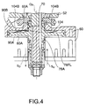
- a wave spring 104 is used instead of the first plate spring 100.
- the wave spring 104 is a ring-shaped spring which has a wave-shaped cross-section in a circumferential direction.
- the upward crest of the wave spring 104 comes in contact with the piston housing 60, and the lower crest comes in contact with the upper surface of the servo piston 78FL in the case of trunnions 46FL and 46RR as shown in Fig. 4.
- the wave spring 104 is disposed in the lower oil chamber 94B, its upper crest comes in contact with the lower surface of the piston 78RL and its lower crest comes in contact with the piston housing 60.
- the wave spring 104 is attached leaving a small clearance with the outer circumference of the boss 78A.
- Guides 104B are also formed in the wave spring. One of the guides 104B comes in contact with the piston housing 60 while the other of the guides 104B comes in contact with the servo piston 78FL (78RR, 78RL) so as to ensure coaxiality of the wave spring 104 with the boss 78A.
- the same effect is obtained as in the aforesaid first embodiment. Further, the contact area with the case 60 and the upper surfaces of the servo pistons 8FL, 78RR and 78RL is larger than when using the first plate spring 100, so wear of parts is prevented and durability of the transmission is further improved.
- Both of the above-mentioned embodiments aim to limit the change of speed ratio when the vehicle is pulled or runs under inertia in the forward direction.
- the change of speed ratio when the vehicle is being pulled or running under its own inertia in the reverse direction can also be suppressed by reversing the direction of the elastic restoring force of the first plate spring 100, i.e., by for example disposing the first plate spring 100 of the first oil chamber 90B, in the second oil chamber 90A.
Landscapes
- Engineering & Computer Science (AREA)
- General Engineering & Computer Science (AREA)
- Mechanical Engineering (AREA)
- Friction Gearing (AREA)
Applications Claiming Priority (2)
| Application Number | Priority Date | Filing Date | Title |
|---|---|---|---|
| JP17493298A JP3259684B2 (ja) | 1998-06-22 | 1998-06-22 | 車両用トロイダル型無段変速機 |
| JP17493298 | 1998-06-22 |
Publications (2)
| Publication Number | Publication Date |
|---|---|
| EP0967413A1 true EP0967413A1 (fr) | 1999-12-29 |
| EP0967413B1 EP0967413B1 (fr) | 2003-05-02 |
Family
ID=15987251
Family Applications (1)
| Application Number | Title | Priority Date | Filing Date |
|---|---|---|---|
| EP99111362A Expired - Lifetime EP0967413B1 (fr) | 1998-06-22 | 1999-06-10 | Transmission continue de vitesse du type torique |
Country Status (4)
| Country | Link |
|---|---|
| US (1) | US6159126A (fr) |
| EP (1) | EP0967413B1 (fr) |
| JP (1) | JP3259684B2 (fr) |
| DE (1) | DE69907321T2 (fr) |
Cited By (3)
| Publication number | Priority date | Publication date | Assignee | Title |
|---|---|---|---|---|
| DE10013182A1 (de) * | 2000-03-17 | 2001-09-20 | Zahnradfabrik Friedrichshafen | Stufenloses Reibradgetriebe |
| US6659906B2 (en) | 2001-05-08 | 2003-12-09 | Nissan Motor Co., Ltd. | Toroidal continuously variable transmission |
| EP1384921A3 (fr) * | 2002-07-26 | 2005-07-20 | JATCO Ltd | Transmission toroidale à variation continue |
Families Citing this family (57)
| Publication number | Priority date | Publication date | Assignee | Title |
|---|---|---|---|---|
| US6551210B2 (en) | 2000-10-24 | 2003-04-22 | Motion Technologies, Llc. | Continuously variable transmission |
| USRE41892E1 (en) | 1997-09-02 | 2010-10-26 | Fallbrook Technologies Inc. | Continuously variable transmission |
| JP3259684B2 (ja) | 1998-06-22 | 2002-02-25 | 日産自動車株式会社 | 車両用トロイダル型無段変速機 |
| EP1149893B1 (fr) * | 2000-04-26 | 2010-12-15 | Colgate-Palmolive Company | Ensemble doseur pour une composition adoucissante utilisable dans un cycle de lavage |
| US6258767B1 (en) * | 2000-04-26 | 2001-07-10 | Colgate-Palmolive Co. | Spherical compacted unit dose softener |
| EP2261537A3 (fr) | 2001-04-26 | 2012-06-13 | Fallbrook Technologies Inc. | Transmission variable continue |
| JP3790191B2 (ja) | 2002-07-18 | 2006-06-28 | ジヤトコ株式会社 | トロイダル型無段変速機 |
| JP3790192B2 (ja) * | 2002-07-26 | 2006-06-28 | ジヤトコ株式会社 | トロイダル型無段変速機 |
| US20040153091A1 (en) * | 2003-02-04 | 2004-08-05 | Marvin Figueroa | Sizing plate and sizing plate extraction |
| US7011600B2 (en) | 2003-02-28 | 2006-03-14 | Fallbrook Technologies Inc. | Continuously variable transmission |
| US7214159B2 (en) | 2003-08-11 | 2007-05-08 | Fallbrook Technologies Inc. | Continuously variable planetary gear set |
| US7166052B2 (en) | 2003-08-11 | 2007-01-23 | Fallbrook Technologies Inc. | Continuously variable planetary gear set |
| CN100554728C (zh) | 2004-07-21 | 2009-10-28 | 瀑溪技术公司 | 滚动牵引的行星传动 |
| JP4974896B2 (ja) | 2004-10-05 | 2012-07-11 | フォールブルック テクノロジーズ インコーポレイテッド | 連続可変変速機 |
| US7600963B2 (en) | 2005-08-22 | 2009-10-13 | Viryd Technologies Inc. | Fluid energy converter |
| ES2439236T3 (es) | 2005-08-24 | 2014-01-22 | Fallbrook Intellectual Property Company Llc | Turbina eólica |
| KR101831828B1 (ko) | 2005-10-28 | 2018-02-23 | 폴브룩 인텔렉츄얼 프로퍼티 컴퍼니 엘엘씨 | 전동 드라이브 |
| CN101495777B (zh) | 2005-11-22 | 2011-12-14 | 福博科技术公司 | 无级变速器 |
| CN102226460A (zh) | 2005-12-09 | 2011-10-26 | 瀑溪技术公司 | 无级变速器 |
| EP1811202A1 (fr) | 2005-12-30 | 2007-07-25 | Fallbrook Technologies, Inc. | Transmission à variation continue |
| US7882762B2 (en) | 2006-01-30 | 2011-02-08 | Fallbrook Technologies Inc. | System for manipulating a continuously variable transmission |
| DE102006010429B3 (de) * | 2006-03-03 | 2007-07-26 | Hochschule Konstanz | Reibrad-Getriebe, insbesondere Reibrad-Ring-Getriebe |
| WO2007106874A2 (fr) | 2006-03-14 | 2007-09-20 | Autocraft Industries, Inc. | Fauteuil roulant ameliore |
| EP2018314A4 (fr) | 2006-05-11 | 2010-04-14 | Fallbrook Technologies Inc | Transmission à variation continue |
| CN102269055B (zh) | 2006-06-26 | 2013-08-28 | 福博科技术公司 | 无级变速器 |
| EP2089642B1 (fr) | 2006-11-08 | 2013-04-10 | Fallbrook Intellectual Property Company LLC | Générateur de force de fixation par serrage |
| EP2125469A2 (fr) | 2007-02-01 | 2009-12-02 | Fallbrook Technologies Inc. | Système et procédés pour la commande d'une transmission et/ou d'un premier moteur d'entraînement |
| US20100093479A1 (en) | 2007-02-12 | 2010-04-15 | Fallbrook Technologies Inc. | Continuously variable transmissions and methods therefor |
| JP5350274B2 (ja) | 2007-02-16 | 2013-11-27 | フォールブルック インテレクチュアル プロパティー カンパニー エルエルシー | 無限可変変速機、連続可変変速機、方法、組立品、部分組立品、およびそのための構成要素 |
| JP5591686B2 (ja) | 2007-04-24 | 2014-09-17 | フォールブルック インテレクチュアル プロパティー カンパニー エルエルシー | 電気牽引駆動装置 |
| US8641577B2 (en) | 2007-06-11 | 2014-02-04 | Fallbrook Intellectual Property Company Llc | Continuously variable transmission |
| BRPI0814410A2 (pt) | 2007-07-05 | 2017-05-23 | Fallbrook Tech Inc | transmissão continuamente variável |
| JP4882965B2 (ja) * | 2007-11-07 | 2012-02-22 | トヨタ自動車株式会社 | トロイダル式無段変速機 |
| CN101861482B (zh) | 2007-11-16 | 2014-05-07 | 福博科知识产权有限责任公司 | 用于变速传动装置的控制器 |
| EP2234869B1 (fr) | 2007-12-21 | 2012-07-04 | Fallbrook Technologies Inc. | Transmissions automatiques et procedes correspondants |
| US8313405B2 (en) | 2008-02-29 | 2012-11-20 | Fallbrook Intellectual Property Company Llc | Continuously and/or infinitely variable transmissions and methods therefor |
| US8317651B2 (en) | 2008-05-07 | 2012-11-27 | Fallbrook Intellectual Property Company Llc | Assemblies and methods for clamping force generation |
| JP5457438B2 (ja) | 2008-06-06 | 2014-04-02 | フォールブルック インテレクチュアル プロパティー カンパニー エルエルシー | 無限可変変速機、及び無限可変変速機用の制御システム |
| JP5230804B2 (ja) | 2008-06-23 | 2013-07-10 | フォールブルック インテレクチュアル プロパティー カンパニー エルエルシー | 連続可変変速機 |
| WO2010017242A1 (fr) | 2008-08-05 | 2010-02-11 | Fallbrook Technologies Inc. | Procédés de commande d'une transmission et/ou d'une machine motrice |
| US8469856B2 (en) | 2008-08-26 | 2013-06-25 | Fallbrook Intellectual Property Company Llc | Continuously variable transmission |
| US8167759B2 (en) | 2008-10-14 | 2012-05-01 | Fallbrook Technologies Inc. | Continuously variable transmission |
| BRPI1012518B1 (pt) | 2009-04-16 | 2019-10-22 | Fallbrook Ip Co Llc | conjunto de estator e mecanismo de mudança de velocidade para uma transmissão continuamente variável |
| US8401768B2 (en) * | 2009-09-01 | 2013-03-19 | Ford Global Technologies, Llc | System and method for restarting an engine |
| US8512195B2 (en) | 2010-03-03 | 2013-08-20 | Fallbrook Intellectual Property Company Llc | Infinitely variable transmissions, continuously variable transmissions, methods, assemblies, subassemblies, and components therefor |
| US8888643B2 (en) | 2010-11-10 | 2014-11-18 | Fallbrook Intellectual Property Company Llc | Continuously variable transmission |
| AU2012240435B2 (en) | 2011-04-04 | 2016-04-28 | Fallbrook Intellectual Property Company Llc | Auxiliary power unit having a continuously variable transmission |
| JP2012219885A (ja) * | 2011-04-07 | 2012-11-12 | Nsk Ltd | トロイダル型無段変速機 |
| WO2013112408A1 (fr) | 2012-01-23 | 2013-08-01 | Fallbrook Intellectual Property Company Llc | Transmissions infiniment variables, procédés de transmissions variables en continu, ensembles, sous-ensembles, et composants à cet effet |
| US9085225B2 (en) | 2012-01-23 | 2015-07-21 | Dennis Ray Halwes | Infinitely variable transmission |
| US8858389B2 (en) * | 2012-01-27 | 2014-10-14 | Gm Global Technology Operations, Llc | Variator assembly |
| JP6660876B2 (ja) | 2013-04-19 | 2020-03-11 | フォールブルック インテレクチュアル プロパティー カンパニー エルエルシー | 連続可変変速機 |
| US10047861B2 (en) | 2016-01-15 | 2018-08-14 | Fallbrook Intellectual Property Company Llc | Systems and methods for controlling rollback in continuously variable transmissions |
| TW201825805A (zh) | 2016-03-18 | 2018-07-16 | 福柏克智慧財產有限責任公司 | 用於無級變速器之定子、定子組件及用於控制無級變速器之方法 |
| US10023266B2 (en) | 2016-05-11 | 2018-07-17 | Fallbrook Intellectual Property Company Llc | Systems and methods for automatic configuration and automatic calibration of continuously variable transmissions and bicycles having continuously variable transmissions |
| US11215268B2 (en) | 2018-11-06 | 2022-01-04 | Fallbrook Intellectual Property Company Llc | Continuously variable transmissions, synchronous shifting, twin countershafts and methods for control of same |
| US11174922B2 (en) | 2019-02-26 | 2021-11-16 | Fallbrook Intellectual Property Company Llc | Reversible variable drives and systems and methods for control in forward and reverse directions |
Citations (5)
| Publication number | Priority date | Publication date | Assignee | Title |
|---|---|---|---|---|
| DE2847919A1 (de) * | 1978-11-04 | 1980-05-22 | Charles Wesley Jackman | Friktionsgetriebe |
| US4434675A (en) * | 1981-09-11 | 1984-03-06 | Excelermatic Inc. | Transmission ratio control arrangement for a precess cam controlled infinitely variable traction roller transmission |
| SU1245785A1 (ru) * | 1985-01-07 | 1986-07-23 | Предприятие П/Я В-2942 | Автоматический торовый вариатор |
| JPS6237562A (ja) * | 1985-08-12 | 1987-02-18 | Nippon Seiko Kk | トロイダル形無段変速機の変速保持装置 |
| JPS6246060A (ja) * | 1985-08-21 | 1987-02-27 | Nippon Seiko Kk | トロイダル形無段変速機の逆変速防止装置 |
Family Cites Families (8)
| Publication number | Priority date | Publication date | Assignee | Title |
|---|---|---|---|---|
| US4126052A (en) * | 1975-12-11 | 1978-11-21 | Jackman Charles W | Friction transmission |
| US4444068A (en) * | 1982-01-26 | 1984-04-24 | Excelermatic Inc. | Infinitely variable traction roller transmission |
| JPS6392859A (ja) * | 1986-10-08 | 1988-04-23 | Honda Motor Co Ltd | 後進機構付き変速装置 |
| US4858484A (en) * | 1987-10-26 | 1989-08-22 | Excelermatic Inc. | Infinitely variable traction roller transmission |
| GB9214190D0 (en) * | 1992-07-03 | 1992-08-12 | Robinson Leslie K | Improvements in or relating to continuously-variable-ratio transmissions of the toroidal-race rolling-traction type |
| US5330396A (en) | 1992-12-16 | 1994-07-19 | The Torax Company, Inc. | Loading device for continuously variable transmission |
| JPH11257479A (ja) * | 1998-03-10 | 1999-09-21 | Honda Motor Co Ltd | トロイダル型無段変速機の制御装置 |
| JP3259684B2 (ja) | 1998-06-22 | 2002-02-25 | 日産自動車株式会社 | 車両用トロイダル型無段変速機 |
-
1998
- 1998-06-22 JP JP17493298A patent/JP3259684B2/ja not_active Expired - Fee Related
-
1999
- 1999-06-08 US US09/327,483 patent/US6159126A/en not_active Expired - Fee Related
- 1999-06-10 EP EP99111362A patent/EP0967413B1/fr not_active Expired - Lifetime
- 1999-06-10 DE DE69907321T patent/DE69907321T2/de not_active Expired - Fee Related
Patent Citations (5)
| Publication number | Priority date | Publication date | Assignee | Title |
|---|---|---|---|---|
| DE2847919A1 (de) * | 1978-11-04 | 1980-05-22 | Charles Wesley Jackman | Friktionsgetriebe |
| US4434675A (en) * | 1981-09-11 | 1984-03-06 | Excelermatic Inc. | Transmission ratio control arrangement for a precess cam controlled infinitely variable traction roller transmission |
| SU1245785A1 (ru) * | 1985-01-07 | 1986-07-23 | Предприятие П/Я В-2942 | Автоматический торовый вариатор |
| JPS6237562A (ja) * | 1985-08-12 | 1987-02-18 | Nippon Seiko Kk | トロイダル形無段変速機の変速保持装置 |
| JPS6246060A (ja) * | 1985-08-21 | 1987-02-27 | Nippon Seiko Kk | トロイダル形無段変速機の逆変速防止装置 |
Non-Patent Citations (3)
| Title |
|---|
| PATENT ABSTRACTS OF JAPAN vol. 011, no. 221 (M - 608) 17 July 1987 (1987-07-17) * |
| PATENT ABSTRACTS OF JAPAN vol. 011, no. 234 (M - 611) 30 July 1987 (1987-07-30) * |
| SOVIET INVENTIONS ILLUSTRATED Section PQ Week 8711, 25 March 1987 Derwent World Patents Index; Class Q64, AN 87-078306, XP002116873 * |
Cited By (5)
| Publication number | Priority date | Publication date | Assignee | Title |
|---|---|---|---|---|
| DE10013182A1 (de) * | 2000-03-17 | 2001-09-20 | Zahnradfabrik Friedrichshafen | Stufenloses Reibradgetriebe |
| US6659906B2 (en) | 2001-05-08 | 2003-12-09 | Nissan Motor Co., Ltd. | Toroidal continuously variable transmission |
| EP1256744A3 (fr) * | 2001-05-08 | 2005-07-27 | Nissan Motor Company, Limited | Transmission continue de vitesse toroidale |
| EP1384921A3 (fr) * | 2002-07-26 | 2005-07-20 | JATCO Ltd | Transmission toroidale à variation continue |
| US7192380B2 (en) | 2002-07-26 | 2007-03-20 | Jatco Ltd | Toroidal continuously variable transmission |
Also Published As
| Publication number | Publication date |
|---|---|
| DE69907321T2 (de) | 2004-01-22 |
| JP3259684B2 (ja) | 2002-02-25 |
| DE69907321D1 (de) | 2003-06-05 |
| JP2000009197A (ja) | 2000-01-11 |
| US6159126A (en) | 2000-12-12 |
| EP0967413B1 (fr) | 2003-05-02 |
Similar Documents
| Publication | Publication Date | Title |
|---|---|---|
| US6159126A (en) | Toroidal continuously variable transmission | |
| US6440035B2 (en) | Continuously variable transmission for motor vehicles | |
| EP1593879A1 (fr) | Transmission de traction a variateur | |
| US5144850A (en) | Continuously variable traction roller transmission | |
| US5368529A (en) | Toroidal type continuously variable transmission | |
| US5057061A (en) | Continuously variable speed transmission | |
| US6475111B2 (en) | Toroidal continuously variable transmission | |
| JPH10281269A (ja) | トロイダル型無段変速機 | |
| JP3752587B2 (ja) | トロイダル型無段変速機 | |
| JP2000205359A (ja) | ハ―フトロイダル型無段変速機 | |
| JP2004169719A (ja) | トロイダル型無段変速機及び無段変速装置 | |
| US20100184558A1 (en) | Friction type continuously variable transmission | |
| US5484346A (en) | Stepless speed changing apparatus | |
| GB2320070A (en) | Toroidal race continuously-variable transmission | |
| EP0738846A2 (fr) | Transmission continue à courroie | |
| US6231473B1 (en) | Toroidal continuously variable transmission | |
| US6666789B2 (en) | Frictional variable transmission for vehicle | |
| US6248039B1 (en) | Toroidal continuously variable transmission | |
| US6514171B2 (en) | Toroidal continuously variable transmission | |
| US4934205A (en) | Stepless speed change device | |
| JP2000257685A (ja) | トロイダル形無段変速装置 | |
| KR100313808B1 (ko) | 벨트식 무단 변속기의 무단 변속기구 | |
| KR0174168B1 (ko) | 무단 변속장치 | |
| JP2005172065A (ja) | トラクションドライブ式無段変速機 | |
| JP2005226842A (ja) | トラクションドライブ式無段変速機 |
Legal Events
| Date | Code | Title | Description |
|---|---|---|---|
| PUAI | Public reference made under article 153(3) epc to a published international application that has entered the european phase |
Free format text: ORIGINAL CODE: 0009012 |
|
| 17P | Request for examination filed |
Effective date: 19990610 |
|
| AK | Designated contracting states |
Kind code of ref document: A1 Designated state(s): DE FR GB |
|
| AX | Request for extension of the european patent |
Free format text: AL;LT;LV;MK;RO;SI |
|
| AKX | Designation fees paid |
Free format text: DE FR GB |
|
| 17Q | First examination report despatched |
Effective date: 20011221 |
|
| GRAH | Despatch of communication of intention to grant a patent |
Free format text: ORIGINAL CODE: EPIDOS IGRA |
|
| GRAH | Despatch of communication of intention to grant a patent |
Free format text: ORIGINAL CODE: EPIDOS IGRA |
|
| GRAA | (expected) grant |
Free format text: ORIGINAL CODE: 0009210 |
|
| AK | Designated contracting states |
Designated state(s): DE FR GB |
|
| REG | Reference to a national code |
Ref country code: GB Ref legal event code: FG4D |
|
| REF | Corresponds to: |
Ref document number: 69907321 Country of ref document: DE Date of ref document: 20030605 Kind code of ref document: P |
|
| ET | Fr: translation filed | ||
| PLBE | No opposition filed within time limit |
Free format text: ORIGINAL CODE: 0009261 |
|
| STAA | Information on the status of an ep patent application or granted ep patent |
Free format text: STATUS: NO OPPOSITION FILED WITHIN TIME LIMIT |
|
| 26N | No opposition filed |
Effective date: 20040203 |
|
| PGFP | Annual fee paid to national office [announced via postgrant information from national office to epo] |
Ref country code: GB Payment date: 20090610 Year of fee payment: 11 Ref country code: DE Payment date: 20090604 Year of fee payment: 11 |
|
| GBPC | Gb: european patent ceased through non-payment of renewal fee |
Effective date: 20100610 |
|
| REG | Reference to a national code |
Ref country code: FR Ref legal event code: ST Effective date: 20110228 |
|
| PG25 | Lapsed in a contracting state [announced via postgrant information from national office to epo] |
Ref country code: DE Free format text: LAPSE BECAUSE OF NON-PAYMENT OF DUE FEES Effective date: 20110101 |
|
| PG25 | Lapsed in a contracting state [announced via postgrant information from national office to epo] |
Ref country code: FR Free format text: LAPSE BECAUSE OF NON-PAYMENT OF DUE FEES Effective date: 20100630 |
|
| PG25 | Lapsed in a contracting state [announced via postgrant information from national office to epo] |
Ref country code: GB Free format text: LAPSE BECAUSE OF NON-PAYMENT OF DUE FEES Effective date: 20100610 |
|
| PGFP | Annual fee paid to national office [announced via postgrant information from national office to epo] |
Ref country code: FR Payment date: 20090611 Year of fee payment: 11 |