EP0968572B1 - Telephone sans fil a entrees multiples comportant une suppression d'echos - Google Patents
Telephone sans fil a entrees multiples comportant une suppression d'echos Download PDFInfo
- Publication number
- EP0968572B1 EP0968572B1 EP98911808A EP98911808A EP0968572B1 EP 0968572 B1 EP0968572 B1 EP 0968572B1 EP 98911808 A EP98911808 A EP 98911808A EP 98911808 A EP98911808 A EP 98911808A EP 0968572 B1 EP0968572 B1 EP 0968572B1
- Authority
- EP
- European Patent Office
- Prior art keywords
- echo
- signal
- summer
- digital
- speaker
- Prior art date
- Legal status (The legal status is an assumption and is not a legal conclusion. Google has not performed a legal analysis and makes no representation as to the accuracy of the status listed.)
- Expired - Lifetime
Links
- 230000001629 suppression Effects 0.000 title 1
- 238000000034 method Methods 0.000 claims abstract description 21
- 238000004891 communication Methods 0.000 claims description 16
- 230000001131 transforming effect Effects 0.000 claims 4
- 230000008859 change Effects 0.000 abstract description 3
- 230000003044 adaptive effect Effects 0.000 description 7
- 230000008901 benefit Effects 0.000 description 6
- 238000010586 diagram Methods 0.000 description 6
- 230000003071 parasitic effect Effects 0.000 description 4
- 230000005540 biological transmission Effects 0.000 description 3
- 230000001413 cellular effect Effects 0.000 description 3
- 230000008878 coupling Effects 0.000 description 3
- 238000010168 coupling process Methods 0.000 description 3
- 238000005859 coupling reaction Methods 0.000 description 3
- 230000004044 response Effects 0.000 description 3
- 238000001228 spectrum Methods 0.000 description 2
- 206010019133 Hangover Diseases 0.000 description 1
- 230000015556 catabolic process Effects 0.000 description 1
- 238000006243 chemical reaction Methods 0.000 description 1
- 238000006731 degradation reaction Methods 0.000 description 1
- 230000001419 dependent effect Effects 0.000 description 1
- 230000009977 dual effect Effects 0.000 description 1
- 238000002592 echocardiography Methods 0.000 description 1
- 230000008569 process Effects 0.000 description 1
- 230000003595 spectral effect Effects 0.000 description 1
Images

Classifications
-
- H—ELECTRICITY
- H04—ELECTRIC COMMUNICATION TECHNIQUE
- H04B—TRANSMISSION
- H04B7/00—Radio transmission systems, i.e. using radiation field
- H04B7/015—Reducing echo effects
-
- H—ELECTRICITY
- H04—ELECTRIC COMMUNICATION TECHNIQUE
- H04M—TELEPHONIC COMMUNICATION
- H04M9/00—Arrangements for interconnection not involving centralised switching
- H04M9/08—Two-way loud-speaking telephone systems with means for conditioning the signal, e.g. for suppressing echoes for one or both directions of traffic
- H04M9/082—Two-way loud-speaking telephone systems with means for conditioning the signal, e.g. for suppressing echoes for one or both directions of traffic using echo cancellers
-
- H—ELECTRICITY
- H04—ELECTRIC COMMUNICATION TECHNIQUE
- H04B—TRANSMISSION
- H04B3/00—Line transmission systems
- H04B3/02—Details
- H04B3/20—Reducing echo effects or singing; Opening or closing transmitting path; Conditioning for transmission in one direction or the other
- H04B3/23—Reducing echo effects or singing; Opening or closing transmitting path; Conditioning for transmission in one direction or the other using a replica of transmitted signal in the time domain, e.g. echo cancellers
Definitions
- the present invention relates to digital communications. More particularly, the present invention relates to a novel and improved method and apparatus for canceling echo in a Wireless Local Loop telephone system.
- CDMA code division multiple access
- a multiple access technique wherein a large number of mobile telephone system users, each having a transceiver, communicate through satellite repeaters or terrestrial base stations (also known as base stations, or cell-sites) using code division multiple access (CDMA) spread spectrum communication signals.
- CDMA code division multiple access
- Wire based or wire line telephone systems are the traditional method of providing non-mobile telephone service.
- Wire based telephone systems are well suited for this task because they provide high quality telephone connections at a low operating cost and can easily accommodate increased demand for telephone service by the introduction of new telephone wires into the existing network.
- a disadvantage of wire based telephone systems is the substantial infrastructure and capital necessary for their implementation. These requirements can make wire based telephone systems uneconomical for providing telephone service in areas that are remote or less populated, or in less developed areas where the required capital is not available. The result is that these less populated and required capital is not available. The result is that these less populated and developed areas often lack adequate telephone service. Also, the time necessary to put the required infrastructure in place makes wire based telephone systems less desirable in areas where new telephone service must be provided quickly.
- Wireless cellular telephone systems require substantially less capital and infrastructure than wire based telephone systems and therefore provide a possible alternative for providing primary telephone service in areas where access to wire based telephone service is inadequate.
- Such wireless cellular systems are known as Wireless Local Loop (WLL).
- WLL Wireless Local Loop
- ISS Integrated Subscriber System
- the ISS unit contains a handset and a keypad, looking and functioning like an ordinary home telephone. Speech is provided from the integrated handset to the ISS base unit and converted into digital format so that it can be processed in accordance with CDMA techniques, as described in aforementioned patents '307 and '459.
- SSS Single Subscriber System
- An SSS unit can be used in a home where multiple standard telephone sets are used, each telephone having the same ESN so that only one call may be placed or received at one time. Users can pick up a second line and actively participate in the conversation, each home user able to communicate with the far end speaker as well as each other, similar to multiple phone extensions in the home.
- Echo is a problem that must be addressed for both ISS and SSS WLL subscriber stations.
- an earseal echo is generated at the ISS handset causing the far end speaker to hear an annoying echo of his own voice.
- an echo results from the impedance mismatch in a 4-to-2-wire converter, known as a hybrid, within the SSS unit.
- the 4-to-2 wire conversion is needed so that standard analog telephones can be interfaced to the SSS.
- the echo problem is alleviated using a single network echo canceller located inside the ISS or SSS unit.
- An example of a network echo canceller is disclosed in U.S. Patent No. 5,307,405 (the '405 patent) entitled "NETWORK ECHO CANCELLER" assigned to the assignee of the present invention and incorporated by reference herein.
- the echo canceller can be optimized to cancel the earseal echo.
- the echo canceller can be optimized to cancel the hybrid echo.
- US-A-4,935,919 discloses an echo canceller in a modem that cancels echoes from hybrid transformers on both the near end and the far end.
- the echo canceller has a variable delay which may be adjusted to conform to a round trip of an echo.
- An adaptive filter has a number of delay circuits, each adding an increment of delay. A number of these delay circuits are selected in order to provide a selected delay time.
- the present invention is method and apparatus for combining an ISS unit and an SSS unit to allow conference calls between two near-end users and a far-end user.
- the combined unit known as and ISS/SSS unit, also reduces echo to the far-end user resulting from the impedance characteristics of the analog telephones and the ISS input.
- the ISS/SSS unit uses two echo cancellers to reduce the echo signals. One echo canceller is optimized to eliminate the earseal echo resulting from the ISS handset and the other is optimized to remove a hybrid echo resulting from the analog telephone inputs.
- each echo canceller can be specifically designed to eliminate the particular type of echo to be canceled.
- Another advantage of the present invention is fast echo canceller filter convergence because a near end silent state is more likely to occur with a single near end speaker than in a multi-user situation.
- a wireless telephone for allowing two or more users to communicate simultaneously with each other and a far end user, comprising a dedicated handset for providing a first telephonic input and at least one interface for receiving an analog telephone input.
- the present invention is able to cancel both earseal echo and hybrid echo in a digital telephone system, said system comprising a far end speaker in wireless communication with at least two near end speakers, said near end speakers using a wireless subscriber unit, said subscriber unit having at least two user interfaces, one interface being a dedicated handset, and at least one other interface being a 2-wire, standard analog telephone, said standard analog telephone connected to said subscriber unit via a 4-to-2 wire hybrid, wherein said subscriber unit allows simultaneous communication between said far end speaker, a first near end speaker using said dedicated handset, and a second speaker using said standard analog telephone, said apparatus comprising a first echo canceling means located within said subscriber unit for eliminating said earseal echo generated at said dedicated handset and a second echo canceling means located within said subscriber unit for eliminating said hybrid echo generated at said 4-to-2 wire hybrid.
- the present invention discloses a Wireless Local Loop telephone system, called an ISS/SSS unit, which includes a handset and keypad as one telephonic interface, herein denoted as ISS, and other telephonic interfaces provided by standard analog telephones connected to the ISS/SSS unit via standard RJ-11x jacks, herein denoted as SSS.
- ISS/SSS unit which includes a handset and keypad as one telephonic interface, herein denoted as ISS, and other telephonic interfaces provided by standard analog telephones connected to the ISS/SSS unit via standard RJ-11x jacks, herein denoted as SSS.
- SSS standard analog telephones connected to the ISS/SSS unit via standard RJ-11x jacks
- ISS/SSS unit One problem with the ISS/SSS unit is the presence of echo generated by the ISS and SSS interfaces to the far end speaker. For example, in a three way call between a far end speaker, an ISS speaker and a SSS speaker, an echo signal is generated by acoustic coupling between earpiece speaker and microphone at the ISS handset, while another echo signal results from the impedance mismatch developed at the 4-to-2-wire hybrid associated with the SSS interface.
- far end speaker denotes the person who is not using the ISS/SSS unit while the term "near end speaker" denotes the speaker using the ISS/SSS unit.
- FIG. 1 is an overall block diagram of a WLL ISS/SSS subscriber station, denoted as ISS/SSS unit 2. Near end speakers may use either ISS handset 16 or analog telephone 18 or 20 to place and receive calls. Multiple analog telephones may be interfaced to ISS/SSS unit 2, denoted in FIG. 1 as including analog telephone 20.
- the interface between ISS handset 16 and codec 14 is a 4-wire interface, while the connections between subscriber line interface 12 and analog telephones 18 through 20 are each 2-wire. For purposes of discussion herein, it will be assumed that only analog telephone 18 is connected to ISS/SSS unit 2.
- Three-way switch 10 controls communications between the far end speaker and ISS/SSS speaker(s). If only one speaker is using ISS/SSS unit 2, communications between that speaker and the far end speaker are routed through three-way switch 10 to either ISS handset 16 or analog telephone 18, depending, of course, which interface the near end speaker is using.
- Three way switch 10, in the exemplary embodiment, is configured in digital processor form, such as model ADSP-2181 of the ADSP-2100 series of digital signal processors manufactured by Analog Devices of Norwood, Massachusetts. It should be understood that other digital signal processors may be programmed to function in accordance with the teachings herein. Alternatively, other implementations of three way switch 10 may be configured from discrete processors or in application specific integrated circuit (ASIC) form.
- ASIC application specific integrated circuit
- ISS handset 16 When ISS handset 16 is in use, speech from the near end speaker is provided to codec 14 where it is transformed from an analog signal into digitized PCM data samples. If no other near end speaker is using ISS/SSS unit 2, the digital samples are routed to modem 8, where the PCM samples are encoded into data packets that are modulated using any number of techniques including TDMA, FDMA, or CDMA. The modulated data is then provided to RF module 6, where it is upconverted to a high frequency signal and then transmitted via antenna 4 to remote base station(s), which are not shown.
- Received speech from the far end user arrives at antenna 4 as a high frequency signal which has been modulated in accordance with the particular modulation method used.
- RF module 6 downconverts the signal down to baseband, filters and amplifies the signal, and provides it to modem 8 for demodulation.
- the received packet data is decoded into digital PCM samples in modem 8 and is provided to three way switch 10 where it is routed to codec 14 when only ISS handset 16 is being used.
- Codec 14 accepts the PCM data and converts it into an analog signal, where it is then provided to handset 16 via a four-wire interface.
- Analog telephone 18 When analog telephone 18 is in use, speech from the near end speaker is provided from analog telephone 18 to subscriber line interface 12 via a two-wire connection.
- Analog telephone 18 contains a hybrid which combines the two-wire microphone signal with the two wire earpiece speaker signal to produce a two wire signal to ISS/SSS unit 2.
- Subscriber line interface 12 contains a 4-to-2-wire hybrid converter which converts the two wire signal from analog telephone 18 into a 2-wire transmit signal and a 2-wire receive signal.
- Subscriber Line Interface 12 also contains a codec used to transform the analog near end speech signal into digital PCM samples.
- the PCM samples are then provided to three way switch 10 where it is routed to modem 8 where the PCM samples are encoded into data packets that are modulated in accordance with the chosen modulation method.
- the modulated data is then provided to RF module 6 where is upconverted and then transmitted via antenna 4.
- Received speech is processed in the same way as described above for the ISS case. If only analog telephone 18 is being used, the demodulated PCM signal from modem 8 is sent through three way switch 10 to subscriber line interface 12 only. There, the PCM signal is converted into an analog speech signal and then converted to a 2-wire signal by the hybrid located within subscriber line unit 12. The analog speech signal is then provided to analog telephone 18.
- a conference call can be described in which there are at least three speakers carrying on a conversation: one far end speaker, one near end speaker using ISS handset 16 , and a second near end speaker using analog telephone 18.
- three way switch 10 provides communications between all parties.
- the ISS speaker will be able to communicate with both the far end speaker and the analog telephone speaker simultaneously.
- the analog telephone speaker will be able to communicate with both the far end speaker and the ISS speaker simultaneously.
- the far end speaker will be able to communicate with both the ISS speaker and the analog telephone speaker simultaneously.
- An echo signal is produced both by acoustic coupling at ISS handset 16 and as a result of an impedance mismatch at subscriber line interface 12. As a result, the far end speaker will hear an annoying echo of his own voice.
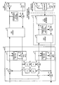
- FIG. 2 is a detailed block diagram of three way switch 10, codec 14, and subscriber line interface 12.
- the present invention introduces two echo cancellers into the three way switch design.
- Echo canceller (EC1) 30 is used to cancel the earseal echo from handset 16 while echo canceller (EC2) 32 is used to cancel the hybrid echo created by hybrid 44.
- EC1 30 is comprised of adaptive filter block 34 which is used to estimate the unknown echo channel characteristics and summer 22 which subtracts the estimated echo signal from the near end speech signal.
- EC2 32 operates in similar fashion, and is comprised of adaptive filter block 36 and summer 28.
- echo cancellers 30 and 32 are provided in the manner disclosed in the aforementioned '405 patent entitled "NETWORK ECHO CANCELLER.”
- received speech from the far end speaker in the form of PCM samples are provided by modem 8 to summer 20 and summer 24.
- digitized speech samples from the analog telephone speaker are added to the far end digitized speech after passing through delay element 68 and attenuation element 70.
- Attenuation element 70 is an optional feature that is used to prevent the analog speaker's voice from being fed back along the return path from the ISS handset. This might occur when echo canceller 30 has not fully adapted to unknown echo channel 46 during the first few seconds of a call.
- Delay element 68 is a parasitic result of attenuator 70 and is thus not a physical element of the system.
- the combined signal from summer 20 is provided to codec 14, where it is converted into an analog waveform and sent to ISS handset 16.
- the ISS speaker can hear both the far end speaker and the analog telephone speaker.
- the combined digital signal from summer 20 is also provided to EC1 30 for use as a reference signal to cancel the earseal echo from ISS handset 16.
- An earseal echo is created by acoustic coupling of the received speech from earpiece speaker 50 to microphone 52 in ISS handset 16 and is modeled as passing through unknown echo channel 46 and added at summer 54. It should be understood that unknown echo channel 46 and summer 54 are not included elements in the system itself, but rather are parasitic results from the physical proximity of microphone 52 and earpiece speaker 50.
- Attenuator 66 is an optional feature that is used to prevent the ISS speaker's voice from being fed back along the return path from the SSS handset(s). This might occur when echo canceller 32 has not fully adapted to unknown echo channel 48 during the first few seconds of a call.
- Delay element 64 is a parasitic result of attenuator 66 and is thus not a physical element of the system.
- the combined digital signal from summer 24 is provided to codec 42 where it is converted into an analog signal.
- the analog signal is then provided to hybrid 44 where it is converted into a 2 wire signal and then onto analog telephone 18 where it is received by hybrid 58.
- Hybrid 58 converts the two wire signal into a four wire signal: two wires to speaker 60 and two wires to microphone 62.
- the combined digital signal from summer 24 is also provided to EC2 32 where it is used as a reference signal to cancel the echo resulting from hybrid 44.
- a hybrid echo is created by an impedance mismatch at hybrid 44 which causes the received analog speech signal to couple to the transmitted speech from the analog telephone speaker, modeled as passing through unknown echo canceller 48 and added at summer 56.
- unknown echo channel 48 and summer 56 are not included elements in the system itself, but rather are parasitic results from the impedance mismatch at hybrid 44.
- Speech from the ISS speaker is received by microphone 52 in ISS handset 16 and an echo signal is added to it, modeled by summer 54, as discussed above.
- the speech-plus-echo signal is provided to codec 14 in analog form and converted to digital PCM samples.
- the PCM samples are provided to summer 22 where an estimated echo signal is subtracted from it, resulting in an echo free signal which is then provided to summer 26.
- digitized speech from the analog telephone speaker is added to the echo canceled speech from summer 22 and then provided to modem 8 for modulation and eventual transmission to the far end speaker.
- Speech from the analog telephone speaker is received by microphone 62 inside analog telephone 18.
- the analog speech is provided to hybrid 58 inside analog telephone 18 where it is converted into a two-wire signal.
- the two-wire signal is provided to hybrid 44 inside ISS/SSS unit 2 and converted back into a four-wire signal: 2 wires for transmitted signals and 2 wires for received signals.
- An echo signal is added to the speech signal at summer 56, as described above.
- the analog speech-plus-echo signal is then provided to codec 42 where it is converted into digital PCM samples and provided to summer 28.
- An estimated echo signal generated by adaptive filter 36 is subtracted from the digital speech-plus-echo signal, leaving an echo canceled speech signal which is provided to summer 26.
- Speech from the ISS speaker is added to the echo free speech at summer 26 and is then provided to modem 8 for modulation and transmission to the far end speaker.
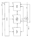
- FIG. 3 is a simplified functional block diagram of echo canceller 30.
- the figure is equally applicable to echo canceller 32.
- Full details of the echo canceller is disclosed in the aforementioned '405 patent. It should be understood that in the exemplary embodiment, echo canceller 30 and 32 are in essence state machines with defined functions for each of the different states of operation.
- the states in which echo canceller 30 and 32 operate are silence, far-end speech, near-end speech, doubletalk, and hangover.
- echo canceller 30 the received far end speech plus the echo canceled speech from summer 28 is labeled as x(n), while the received speech signal from the ISS near end is labeled as v(n). It should be understood that both x(n) and v(n) are digital representations of the analog speech waveforms.
- the input far-end speech x(n) is stored in buffer 100 for input to state filter 102, echo canceller filter 104 and control unit 106.
- state filter 102 and echo canceller filter 104 each have 256 taps. It should be understood that state filter 102 and echo canceller filter 104 may use a greater or lesser number of taps depending upon whether the echo to be canceled is an earseal echo or a hybrid echo.
- filters 102 and 104 track the unknown echo channel. While filter 104 performs the actual echo cancellation, filter 102 is used by the control unit 106 to determine which of several states echo canceller 30 should be operating in. For this reason, filters 102 and 104 are respectively referred to as the state filter and the echo canceller filter.
- the advantage of this two-filter approach is that the filter coefficients of echo canceller filter 104, which model unknown echo channel, can be preserved more effectively without risk of degradation from near-end speech. State determination from state filter 102 is provided to control unit 106 where it is used to decide at when to adjust the tap coefficients to state filter 102 and echo canceller filter 104.
- Echo canceller filter 104 provides an echo replica signal y(n) to one input of summer 22 where it is subtracted from the signal v(n).
- the echo replica signal y(n) is generated by estimating the impulse response of the unknown echo channel during periods of near end silence.
- the resultant echo suppressed signal e(n) output from summer 22 is fed back as an input to control unit 106 and is also provided to summer 26 and delay element 36, shown in FIG. 2.
- echo canceller filter 104 and state filter 102 do not have to adapt their filter tap coefficients in response to the channel change. This results in a more accurate echo estimation signal.
- echo canceller 30 can adapt when the ISS speaker is silent and the far end speaker or analog telephone speaker is talking.
- echo canceller 32 can adapt when the analog telephone speaker is silent and the far end speaker or ISS speaker is talking. If it is assumed that the active speech durations are evenly distributed between each speaker, each echo canceller can adapt two-thirds of the time. If a single echo canceller was used, it could only adapt one-third of the time.
- Echo canceller filter 104 and state filter 102 can only determine the unknown echo channel characteristics and converge when the near end speaker is silent. If only one near end speaker is assigned to each echo canceller, a near end silent state is much more likely to occur than if there is more than one near end speaker assigned to a single echo canceller.
Landscapes
- Engineering & Computer Science (AREA)
- Signal Processing (AREA)
- Computer Networks & Wireless Communication (AREA)
- Cable Transmission Systems, Equalization Of Radio And Reduction Of Echo (AREA)
- Telephonic Communication Services (AREA)
- Telephone Function (AREA)
- Investigating Or Analyzing Materials By The Use Of Ultrasonic Waves (AREA)
Claims (11)
- Dispositif pour supprimer l'écho local et l'écho hybride dans un système de boucle locale sans fil, le système comprenant un haut-parleur lointain dans la communication sans fil et au moins deux haut-parleurs proches, les haut-parleurs lointains utilisant un poste d'abonné sans fil (2), le poste d'abonné (2) comportant au moins deux interfaces d'utilisateur, une première interface étant un poste dédié (16), et au moins une autre interface étant un téléphone analogique classique (18) bifilaire, le téléphone analogique classique (18) étant connecté au poste d'abonné (2) par l'intermédiaire d'un connecteur hybride 4-fils/2-fils (44), dans lequel le poste d'abonné permet une communication simultanée entre le haut-parleur lointain, un premier haut-parleur proche utilisant le poste dédié (16) et un second haut-parleur utilisant le téléphone analogique classique (18), ce dispositif comprenant :un premier moyen de suppression d'écho (30) disposé dans le poste d'abonné (2) pour éliminer l'écho local produit au niveau du poste dédié (16) ; etun second moyen de suppression d'écho (32) disposé dans le poste d'abonné (2) pour éliminer l'écho hybride produit au niveau du connecteur hybride 4-fils/2-fils (44).
- Dispositif selon la revendication 1, dans lequel le premier moyen de suppression d'écho (30) fonctionne indépendamment du second moyen de suppression d'écho (32).
- Procédé de suppression de l'écho local et de l'écho hybride dans un système de boucle locale sans fil, le système comprenant un haut-parleur lointain dans la communication sans fil et au moins deux haut-parleurs proches, les haut-parleurs proches utilisant un poste d'abonné sans fil (2), le poste d'abonné sans fil (2) comportant au moins deux interfaces d'utilisateur, une première interface étant un poste dédié (16), et au moins une autre interface étant un téléphone analogique classique (18) bifilaire, le téléphone analogique classique (18) étant connecté au poste d'abonné (2) par l'intermédiaire d'un connecteur hybride 4-fils/2-fils (44), dans lequel le poste d'abonné (2) permet une communication simultanée entre le haut-parleur lointain, un premier haut-parleur proche utilisant le poste dédié (16) et un second haut-parleur utilisant le téléphone analogique classique (18), ce procédé comprenant les étapes suivantes :fournir un signal numérique de parole lointain et un premier signal numérique de parole plus écho à partir du poste dédié (16) vers un premier moyen de suppression d'écho (30) ;produire un signal de reproduction de l'écho numérique qui approche le signal d'écho proche ;soustraire le signal de reproduction d'écho numérique du premier signal numérique de parole plus écho pour produire un premier signal.de parole à écho supprimé ;fournir le signal de parole numérique lointain et un second signal numérique de parole plus écho à partir du téléphone analogique classique (18) vers un second moyen de suppression d'écho (32) ;produire un signal numérique de reproduction d'écho qui approche du signal d'écho hybride ; etsoustraire le signal de reproduction d'écho numérique du second signal de parole plus écho pour produire un second signal de parole à écho supprimé.
- Procédé selon la revendication 3, comprenant en outre les étapes suivantes :combiner le premier signal de parole à écho supprimé et le second signal de parole à écho supprimé, etfournir le signal de parole à écho supprimé combiné au haut-parleur lointain.
- Dispositif selon la revendication 1, dans lequel le poste d'abonné sans fil comprend un téléphone sans fil pour permettre à deux utilisateurs ou plus de communiquer simultanément l'un avec l'autre et avec un utilisateur lointain, comprenant :le poste dédié (16) pour fournir une première entrée téléphonique ;au moins une interface (12) pour recevoir une entrée de téléphone analogique ;un premier codeur-décodeur (14) connecté à un commutateur trois voies (10) et au poste (16) pour transformer un premier signal analogique en provenance du poste (16) en un premier signal numérique et pour transformer un second signal numérique en provenance du commutateur trois voies (10) en un second signal analogique ;une interface de ligne d'abonné (12) connectée audit au moins un téléphone analogique (18) et au commutateur trois voies (10) pour transformer un troisième signal analogique en provenance dudit au moins un téléphone analogique (18) en un troisième signal numérique et pour transformer un quatrième signal numérique en provenance du commutateur trois voies (10) en un quatrième signal analogique ;le commutateur trois voies (10) étant connecté au codeur-décodeur (14) à l'interface de ligne d'abonné (12) et à un modem pour combiner le premier signal numérique, le troisième signal numérique et les échantillons de paroles numérisés en provenance d'un utilisateur lointain.
- Dispositif (2) selon la revendication 5, dans lequel l'interface de ligne d'abonné (12) comprend :un second codeur-décodeur (42) ; etun système hybride (44) pour former une interface entre le second codeur-décodeur (42) et ledit au moins un téléphone analogique (18).
- Dispositif (2) selon la revendication 5, dans lequel le premier signal numérique, le troisième signal numérique et les échantillons de paroles numérisés sont sous forme de paquets de données PCM.
- Dispositif selon la revendication 5, dans lequel le commutateur trois voies comprend :un premier moyen de suppression d'écho (30) connecté au premier codeur-décodeur (14), un premier additionneur, un second additionneur et un troisième additionneur pour recevoir le premier signal numérique du premier codeur-décodeur (14) et un premier signal combiné à écho supprimé en provenance du premier additionneur et pour fournir un premier signal combiné à écho supprimé au deuxième additionneur et au troisième additionneur ;un second moyen de suppression d'écho (32) connecté à l'interface de ligne d'abonné, au premier additionneur, au second additionneur et au troisième additionneur pour recevoir le troisième signal numérique de l'interface de ligne d'abonné et un second signal combiné à écho supprimé en provenance du second additionneur et pour fournir un second signal à écho supprimé au premier additionneur et au troisième additionneur ;le premier additionneur (20) ayant une première entrée connectée au second moyen de suppression d'écho et au troisième additionneur, une deuxième entrée connectée au modem pour recevoir les échantillons de paroles numérisés en provenance d'un utilisateur lointain, et une sortie connectée au premier moyen de suppression d'écho et au premier codeur-décodeur, le premier additionneur étant destiné à combiner le second signal à écho supprimé et les échantillons de paroles numérisés pour produire un premier signal à écho supprimé combiné ;le deuxième additionneur (24) ayant une première entrée connectée au premier moyen de suppression d'écho, une deuxième entrée connectée au modem pour recevoir des échantillons de paroles numérisés en provenance d'un utilisateur lointain, et une sortie connectée au second moyen de suppression d'écho et à l'interface de ligne d'abonné, le deuxième sommateur étant destiné à combiner le premier signal à écho supprimé et un cinquième signal numérique pour produire un deuxième signal à écho supprimé combiné ; etle troisième additionneur (26) et une première entrée connectée au deuxième additionneur et au premier moyen de suppression d'écho, une deuxième entrée connectée au premier additionneur et au second moyen de suppression d'écho, et une sortie connectée au modem, le troisième additionneur étant destiné à combiner le premier signal à écho supprimé et le deuxième signal à écho supprimé pour produire un troisième signal à écho supprimé combiné.
- Dispositif selon la revendication 8, comprenant en outre :un premier atténuateur (66) interposé entre le premier additionneur et le premier moyen de suppression d'écho ; etun deuxième atténuateur (70) interposé entre le premier additionneur et le second moyen de suppression d'écho.
- Dispositif selon la revendication 8, comprenant en outre :un premier élément de retard (64) interposé entre le deuxième additionneur et le premier moyen de suppression d'écho ; etun deuxième élément de retard (68) interposé entre le premier additionneur et le second moyen de suppression d'écho.
- Procédé selon la revendication 3, pour assurer une communication entre au moins trois utilisateurs, un premier utilisateur proche utilisant le poste dédié dans un système à boucle locale sans fil, au moins un autre utilisateur proche utilisant le téléphone analogique (18) et un utilisateur lointain, comprenant en outre les étapes suivantes :numériser un premier signal analogique en provenance d'un premier utilisateur proche pour produire un premier signal numérique ;numériser un deuxième signal analogique en provenance d'au moins un utilisateur proche pour produire un deuxième signal numérique ;additionner un signal d'un utilisateur lointain avec le premier signal numérique et fournir un premier signal combiné audit au moins un utilisateur proche ;additionner un signal en provenance d'un utilisateur lointain avec le deuxième signal numérique et fournir un deuxième signal combiné au premier utilisateur proche ; etadditionner le premier signal numérique à un deuxième signal numérique pour fournir un troisième signal combiné à l'utilisateur lointain.
Applications Claiming Priority (3)
| Application Number | Priority Date | Filing Date | Title |
|---|---|---|---|
| US820934 | 1997-03-19 | ||
| US08/820,934 US5999828A (en) | 1997-03-19 | 1997-03-19 | Multi-user wireless telephone having dual echo cancellers |
| PCT/US1998/005372 WO1998042084A1 (fr) | 1997-03-19 | 1998-03-18 | Telephone sans fil a entrees multiples comportant une suppression d'echos |
Publications (2)
| Publication Number | Publication Date |
|---|---|
| EP0968572A1 EP0968572A1 (fr) | 2000-01-05 |
| EP0968572B1 true EP0968572B1 (fr) | 2006-07-26 |
Family
ID=25232090
Family Applications (1)
| Application Number | Title | Priority Date | Filing Date |
|---|---|---|---|
| EP98911808A Expired - Lifetime EP0968572B1 (fr) | 1997-03-19 | 1998-03-18 | Telephone sans fil a entrees multiples comportant une suppression d'echos |
Country Status (16)
| Country | Link |
|---|---|
| US (1) | US5999828A (fr) |
| EP (1) | EP0968572B1 (fr) |
| JP (1) | JP2001516539A (fr) |
| KR (1) | KR20000076309A (fr) |
| CN (1) | CN1135729C (fr) |
| AT (1) | ATE334513T1 (fr) |
| AU (1) | AU741749B2 (fr) |
| BR (1) | BR9808372A (fr) |
| CA (1) | CA2283707A1 (fr) |
| DE (1) | DE69835347T2 (fr) |
| ES (1) | ES2267180T3 (fr) |
| FI (1) | FI120568B (fr) |
| ID (1) | ID24156A (fr) |
| IL (1) | IL131769A (fr) |
| RU (1) | RU2199180C2 (fr) |
| WO (1) | WO1998042084A1 (fr) |
Families Citing this family (40)
| Publication number | Priority date | Publication date | Assignee | Title |
|---|---|---|---|---|
| JP3139405B2 (ja) * | 1997-02-28 | 2001-02-26 | 日本電気株式会社 | エコーキャンセラ |
| US6633604B1 (en) * | 1997-08-11 | 2003-10-14 | Vocal Technologies, Ltd. | Method of improving echo canceller training in modems and of discovering characteristics of a PCM channel |
| US6731748B1 (en) * | 1998-11-30 | 2004-05-04 | Qualcomm Incorporated | Audio interface for satellite user terminals |
| KR100407938B1 (ko) * | 1999-10-11 | 2003-12-01 | 엘지전자 주식회사 | 이동통신시스템의 음성처리장치 |
| CA2390200A1 (fr) * | 1999-11-03 | 2001-05-10 | Charles W. K. Gritton | Systeme de traitement vocal integre pour reseaux a commutation par paquets |
| US20020181699A1 (en) * | 2001-03-23 | 2002-12-05 | Tien Pham | System for convolutional echo cancellation by iterative autocorrelation |
| US6895086B2 (en) | 2001-11-13 | 2005-05-17 | Inmate Telephone, Inc. | 3-Way call detection system and method |
| KR20030052708A (ko) * | 2001-12-21 | 2003-06-27 | 엘지전자 주식회사 | 일체형 무선 가입자 망 시스템 |
| US20040224645A1 (en) * | 2003-05-07 | 2004-11-11 | Ching Liou Chih | Phone handset with wireless technology |
| US7248685B2 (en) * | 2003-08-05 | 2007-07-24 | Inmate Telephone, Inc. | Three-way call detection using steganography |
| US20050285935A1 (en) * | 2004-06-29 | 2005-12-29 | Octiv, Inc. | Personal conferencing node |
| US7860236B2 (en) * | 2007-02-01 | 2010-12-28 | Hewlet-Packard Company | Method and system for echo cancellation in a network switch |
| US20080201158A1 (en) | 2007-02-15 | 2008-08-21 | Johnson Mark D | System and method for visitation management in a controlled-access environment |
| US8542802B2 (en) | 2007-02-15 | 2013-09-24 | Global Tel*Link Corporation | System and method for three-way call detection |
| US10194032B2 (en) | 2007-05-04 | 2019-01-29 | Staton Techiya, Llc | Method and apparatus for in-ear canal sound suppression |
| US11683643B2 (en) | 2007-05-04 | 2023-06-20 | Staton Techiya Llc | Method and device for in ear canal echo suppression |
| US11856375B2 (en) | 2007-05-04 | 2023-12-26 | Staton Techiya Llc | Method and device for in-ear echo suppression |
| US8526645B2 (en) | 2007-05-04 | 2013-09-03 | Personics Holdings Inc. | Method and device for in ear canal echo suppression |
| US8411871B2 (en) * | 2007-08-22 | 2013-04-02 | Lantiq Deutschland Gmbh | Echo cancellation |
| US8630685B2 (en) * | 2008-07-16 | 2014-01-14 | Qualcomm Incorporated | Method and apparatus for providing sidetone feedback notification to a user of a communication device with multiple microphones |
| US9202455B2 (en) * | 2008-11-24 | 2015-12-01 | Qualcomm Incorporated | Systems, methods, apparatus, and computer program products for enhanced active noise cancellation |
| US8498407B2 (en) * | 2008-12-02 | 2013-07-30 | Qualcomm Incorporated | Systems and methods for double-talk detection in acoustically harsh environments |
| CN102341105B (zh) | 2009-02-03 | 2014-09-17 | 微生物公司 | 用作上皮组织、急性和慢性伤口、细菌生物被膜和其他适应症的抗菌剂的铋硫醇 |
| US9028878B2 (en) | 2009-02-03 | 2015-05-12 | Microbion Corporation | Bismuth-thiols as antiseptics for biomedical uses, including treatment of bacterial biofilms and other uses |
| US8630726B2 (en) | 2009-02-12 | 2014-01-14 | Value-Added Communications, Inc. | System and method for detecting three-way call circumvention attempts |
| US9225838B2 (en) | 2009-02-12 | 2015-12-29 | Value-Added Communications, Inc. | System and method for detecting three-way call circumvention attempts |
| US20100304679A1 (en) * | 2009-05-28 | 2010-12-02 | Hanks Zeng | Method and System For Echo Estimation and Cancellation |
| CN107308186A (zh) * | 2010-02-03 | 2017-11-03 | 微生物公司 | 作为抗菌剂用于包括细菌生物膜的治疗的生物医学用途以及其它用途的铋‑硫醇 |
| BR112012019286A2 (pt) * | 2010-02-03 | 2018-06-26 | Microbion Corp | bismuto-tióis como antisséptico para usos biomédicos, que incluem tratamento de biofilmes bacterianos e outros usos |
| EP2444967A1 (fr) * | 2010-10-25 | 2012-04-25 | Fraunhofer-Gesellschaft zur Förderung der Angewandten Forschung e.V. | Suppression d'écho comprenant la modélisation des composants de la réverbération tardive |
| US10572961B2 (en) | 2016-03-15 | 2020-02-25 | Global Tel*Link Corporation | Detection and prevention of inmate to inmate message relay |
| US9609121B1 (en) | 2016-04-07 | 2017-03-28 | Global Tel*Link Corporation | System and method for third party monitoring of voice and video calls |
| WO2018168227A1 (fr) * | 2017-03-16 | 2018-09-20 | パナソニックIpマネジメント株式会社 | Dispositif de suppression d'écho acoustique, et procédé de suppression d'écho acoustique |
| US10027797B1 (en) | 2017-05-10 | 2018-07-17 | Global Tel*Link Corporation | Alarm control for inmate call monitoring |
| US10225396B2 (en) | 2017-05-18 | 2019-03-05 | Global Tel*Link Corporation | Third party monitoring of a activity within a monitoring platform |
| US10860786B2 (en) | 2017-06-01 | 2020-12-08 | Global Tel*Link Corporation | System and method for analyzing and investigating communication data from a controlled environment |
| US9930088B1 (en) | 2017-06-22 | 2018-03-27 | Global Tel*Link Corporation | Utilizing VoIP codec negotiation during a controlled environment call |
| JP7564101B2 (ja) | 2018-07-31 | 2024-10-08 | マイクロビオン コーポレーション | ビスマスチオール組成物及び使用方法 |
| MX2021001276A (es) | 2018-07-31 | 2021-07-15 | Microbion Corp | Composiciones de bismuto-tiol y metodos para tratar heridas. |
| KR102172608B1 (ko) * | 2019-05-02 | 2020-11-02 | 남서울대학교 산학협력단 | 동시통화에 강인한 심층학습 기반 음향반향 제거 장치 및 그 방법 |
Family Cites Families (23)
| Publication number | Priority date | Publication date | Assignee | Title |
|---|---|---|---|---|
| US4712235A (en) * | 1984-11-19 | 1987-12-08 | International Business Machines Corporation | Method and apparatus for improved control and time sharing of an echo canceller |
| US4629829A (en) * | 1984-12-14 | 1986-12-16 | Motorola, Inc. | Full duplex speakerphone for radio and landline telephones |
| JPH0650829B2 (ja) * | 1986-09-16 | 1994-06-29 | 日本電気株式会社 | エコ−キヤンセラ方式モデム |
| US4890315A (en) * | 1987-03-20 | 1989-12-26 | Orion Industries, Inc. | Cellular remote station with multiple coupled units |
| GB2213686A (en) * | 1987-12-09 | 1989-08-16 | Racal Communications Equip | Radio telephone terminal unit |
| US4912758A (en) * | 1988-10-26 | 1990-03-27 | International Business Machines Corporation | Full-duplex digital speakerphone |
| JP2842607B2 (ja) * | 1989-03-13 | 1999-01-06 | 株式会社日立製作所 | エコーキャンセラ、それを備えた通信装置および信号処理方法 |
| RU2011298C1 (ru) * | 1991-04-23 | 1994-04-15 | Омский Институт Инженеров Железнодорожного Транспорта | Устройство снижения уровня помех в аппаратуре связи |
| GB2258370B (en) * | 1991-08-02 | 1995-09-06 | Technophone Ltd | Cellular telephone |
| US5206854A (en) * | 1991-09-24 | 1993-04-27 | At&T Bell Laboratories | Detecting loss of echo cancellation |
| US5271057A (en) * | 1991-10-09 | 1993-12-14 | Bell Communications Research, Inc. | Audio processing system for teleconferencing system |
| JP2792311B2 (ja) * | 1992-01-31 | 1998-09-03 | 日本電気株式会社 | 多チャンネルエコー除去方法および装置 |
| US5307405A (en) * | 1992-09-25 | 1994-04-26 | Qualcomm Incorporated | Network echo canceller |
| US5546459A (en) * | 1993-11-01 | 1996-08-13 | Qualcomm Incorporated | Variable block size adaptation algorithm for noise-robust acoustic echo cancellation |
| US5381475A (en) * | 1993-12-02 | 1995-01-10 | At&T Corp. | Arrangement for suppressing echoes in a digital portable telephone |
| US5577097A (en) * | 1994-04-14 | 1996-11-19 | Northern Telecom Limited | Determining echo return loss in echo cancelling arrangements |
| JP2550914B2 (ja) * | 1994-06-21 | 1996-11-06 | 日本電気株式会社 | 折りたたみ型携帯電話装置 |
| US5812951A (en) * | 1994-11-23 | 1998-09-22 | Hughes Electronics Corporation | Wireless personal communication system |
| US5553137A (en) * | 1994-12-05 | 1996-09-03 | Motorola, Inc. | Method and apparatus for echo canceling in a communication system |
| SE516006C2 (sv) * | 1995-01-10 | 2001-11-05 | Ericsson Telefon Ab L M | Kommunikationssystem för ett företag/organisation |
| US5852661A (en) * | 1995-02-17 | 1998-12-22 | Advanced Micro Devices, Inc. | Adaptive echo cancellation used with echo suppression to reduce short and long duration echoes |
| JP2856113B2 (ja) * | 1995-07-10 | 1999-02-10 | 日本電気株式会社 | エコーキャンセラ |
| US5649012A (en) * | 1995-09-15 | 1997-07-15 | Hughes Electronics | Method for synthesizing an echo path in an echo canceller |
-
1997
- 1997-03-19 US US08/820,934 patent/US5999828A/en not_active Expired - Lifetime
-
1998
- 1998-03-18 DE DE69835347T patent/DE69835347T2/de not_active Expired - Lifetime
- 1998-03-18 RU RU99122027/09A patent/RU2199180C2/ru not_active IP Right Cessation
- 1998-03-18 CA CA002283707A patent/CA2283707A1/fr not_active Abandoned
- 1998-03-18 JP JP54078698A patent/JP2001516539A/ja active Pending
- 1998-03-18 ES ES98911808T patent/ES2267180T3/es not_active Expired - Lifetime
- 1998-03-18 KR KR1019997008410A patent/KR20000076309A/ko not_active Withdrawn
- 1998-03-18 ID IDW991099A patent/ID24156A/id unknown
- 1998-03-18 WO PCT/US1998/005372 patent/WO1998042084A1/fr not_active Ceased
- 1998-03-18 CN CNB988035669A patent/CN1135729C/zh not_active Expired - Fee Related
- 1998-03-18 IL IL13176998A patent/IL131769A/en not_active IP Right Cessation
- 1998-03-18 EP EP98911808A patent/EP0968572B1/fr not_active Expired - Lifetime
- 1998-03-18 BR BR9808372-4A patent/BR9808372A/pt not_active Application Discontinuation
- 1998-03-18 AT AT98911808T patent/ATE334513T1/de not_active IP Right Cessation
- 1998-03-18 AU AU65678/98A patent/AU741749B2/en not_active Ceased
-
1999
- 1999-09-10 FI FI991937A patent/FI120568B/fi not_active IP Right Cessation
Also Published As
| Publication number | Publication date |
|---|---|
| AU741749B2 (en) | 2001-12-06 |
| ATE334513T1 (de) | 2006-08-15 |
| US5999828A (en) | 1999-12-07 |
| JP2001516539A (ja) | 2001-09-25 |
| FI120568B (fi) | 2009-11-30 |
| ID24156A (id) | 2000-07-13 |
| IL131769A0 (en) | 2001-03-19 |
| IL131769A (en) | 2002-11-10 |
| KR20000076309A (ko) | 2000-12-26 |
| CN1135729C (zh) | 2004-01-21 |
| DE69835347T2 (de) | 2007-07-26 |
| BR9808372A (pt) | 2000-05-23 |
| CA2283707A1 (fr) | 1998-09-24 |
| AU6567898A (en) | 1998-10-12 |
| RU2199180C2 (ru) | 2003-02-20 |
| FI19991937A7 (fi) | 1999-11-19 |
| CN1253677A (zh) | 2000-05-17 |
| WO1998042084A1 (fr) | 1998-09-24 |
| DE69835347D1 (de) | 2006-09-07 |
| EP0968572A1 (fr) | 2000-01-05 |
| ES2267180T3 (es) | 2007-03-01 |
Similar Documents
| Publication | Publication Date | Title |
|---|---|---|
| US5999828A (en) | Multi-user wireless telephone having dual echo cancellers | |
| EP0204718B1 (fr) | Combine entierement duplex pour telephones radio et par cable aerien | |
| US5475731A (en) | Echo-canceling system and method using echo estimate to modify error signal | |
| US5696821A (en) | Radiotelephone and method therefor for substantially reducing audio feedback | |
| CN1706174B (zh) | 综合噪声消除及残余回波抑制 | |
| JPH09312595A (ja) | ハンズフリー電話機 | |
| EP0972355B1 (fr) | Procédé et appareil de suppression d'echo des deux cotes d'une connexion | |
| JP4350803B2 (ja) | 電話システムにおける動的な反響消去装置及びパラメーターの選択 | |
| EP2405587B1 (fr) | Annuleur d'écho | |
| Raghavendran | Implementation of an acoustic echo canceller using matlab | |
| MXPA99008572A (en) | Multi-input wireless phone with echo suppression | |
| JPH09181652A (ja) | 反響除去システム | |
| JP3383164B2 (ja) | デジタル式無線電話装置 | |
| JPS6364104B2 (fr) | ||
| JPH05316552A (ja) | 公専接続における構内交換機の音声品質保証方式 | |
| WO1999033323A1 (fr) | Procede et appareil pour une conference telephonique a plusieurs voies avec un telephone haut-parleur en mode duplex integral et une interface de communication numerique sans fil | |
| JPH1188922A (ja) | エコーキャンセラ | |
| JP2002353863A (ja) | エコーキャンセラ | |
| JPH05300559A (ja) | 公専接続における構内交換機の音声品質保証方式 |
Legal Events
| Date | Code | Title | Description |
|---|---|---|---|
| PUAI | Public reference made under article 153(3) epc to a published international application that has entered the european phase |
Free format text: ORIGINAL CODE: 0009012 |
|
| 17P | Request for examination filed |
Effective date: 19990915 |
|
| AK | Designated contracting states |
Kind code of ref document: A1 Designated state(s): AT BE CH DE DK ES FI FR GB GR IE IT LI LU MC NL PT SE |
|
| RIN1 | Information on inventor provided before grant (corrected) |
Inventor name: GUPTA, KUMAR, SAMIR, C/O QUALCOMM INCORPORTED Inventor name: SIH, GILBERT, C. |
|
| RAP1 | Party data changed (applicant data changed or rights of an application transferred) |
Owner name: QUALCOMM INCORPORATED |
|
| 17Q | First examination report despatched |
Effective date: 20040211 |
|
| GRAP | Despatch of communication of intention to grant a patent |
Free format text: ORIGINAL CODE: EPIDOSNIGR1 |
|
| GRAS | Grant fee paid |
Free format text: ORIGINAL CODE: EPIDOSNIGR3 |
|
| GRAA | (expected) grant |
Free format text: ORIGINAL CODE: 0009210 |
|
| AK | Designated contracting states |
Kind code of ref document: B1 Designated state(s): AT BE CH DE DK ES FI FR GB GR IE IT LI LU MC NL PT SE |
|
| PG25 | Lapsed in a contracting state [announced via postgrant information from national office to epo] |
Ref country code: NL Free format text: LAPSE BECAUSE OF FAILURE TO SUBMIT A TRANSLATION OF THE DESCRIPTION OR TO PAY THE FEE WITHIN THE PRESCRIBED TIME-LIMIT Effective date: 20060726 Ref country code: LI Free format text: LAPSE BECAUSE OF FAILURE TO SUBMIT A TRANSLATION OF THE DESCRIPTION OR TO PAY THE FEE WITHIN THE PRESCRIBED TIME-LIMIT Effective date: 20060726 Ref country code: IT Free format text: LAPSE BECAUSE OF FAILURE TO SUBMIT A TRANSLATION OF THE DESCRIPTION OR TO PAY THE FEE WITHIN THE PRESCRIBED TIME-LIMIT;WARNING: LAPSES OF ITALIAN PATENTS WITH EFFECTIVE DATE BEFORE 2007 MAY HAVE OCCURRED AT ANY TIME BEFORE 2007. THE CORRECT EFFECTIVE DATE MAY BE DIFFERENT FROM THE ONE RECORDED. Effective date: 20060726 Ref country code: CH Free format text: LAPSE BECAUSE OF FAILURE TO SUBMIT A TRANSLATION OF THE DESCRIPTION OR TO PAY THE FEE WITHIN THE PRESCRIBED TIME-LIMIT Effective date: 20060726 Ref country code: BE Free format text: LAPSE BECAUSE OF FAILURE TO SUBMIT A TRANSLATION OF THE DESCRIPTION OR TO PAY THE FEE WITHIN THE PRESCRIBED TIME-LIMIT Effective date: 20060726 Ref country code: AT Free format text: LAPSE BECAUSE OF FAILURE TO SUBMIT A TRANSLATION OF THE DESCRIPTION OR TO PAY THE FEE WITHIN THE PRESCRIBED TIME-LIMIT Effective date: 20060726 |
|
| REG | Reference to a national code |
Ref country code: GB Ref legal event code: FG4D |
|
| REG | Reference to a national code |
Ref country code: CH Ref legal event code: EP |
|
| REG | Reference to a national code |
Ref country code: IE Ref legal event code: FG4D |
|
| REF | Corresponds to: |
Ref document number: 69835347 Country of ref document: DE Date of ref document: 20060907 Kind code of ref document: P |
|
| REG | Reference to a national code |
Ref country code: SE Ref legal event code: TRGR |
|
| PG25 | Lapsed in a contracting state [announced via postgrant information from national office to epo] |
Ref country code: DK Free format text: LAPSE BECAUSE OF FAILURE TO SUBMIT A TRANSLATION OF THE DESCRIPTION OR TO PAY THE FEE WITHIN THE PRESCRIBED TIME-LIMIT Effective date: 20061026 |
|
| PG25 | Lapsed in a contracting state [announced via postgrant information from national office to epo] |
Ref country code: PT Free format text: LAPSE BECAUSE OF FAILURE TO SUBMIT A TRANSLATION OF THE DESCRIPTION OR TO PAY THE FEE WITHIN THE PRESCRIBED TIME-LIMIT Effective date: 20061226 |
|
| NLV1 | Nl: lapsed or annulled due to failure to fulfill the requirements of art. 29p and 29m of the patents act | ||
| REG | Reference to a national code |
Ref country code: ES Ref legal event code: FG2A Ref document number: 2267180 Country of ref document: ES Kind code of ref document: T3 |
|
| ET | Fr: translation filed | ||
| PLBE | No opposition filed within time limit |
Free format text: ORIGINAL CODE: 0009261 |
|
| STAA | Information on the status of an ep patent application or granted ep patent |
Free format text: STATUS: NO OPPOSITION FILED WITHIN TIME LIMIT |
|
| 26N | No opposition filed |
Effective date: 20070427 |
|
| PG25 | Lapsed in a contracting state [announced via postgrant information from national office to epo] |
Ref country code: MC Free format text: LAPSE BECAUSE OF NON-PAYMENT OF DUE FEES Effective date: 20070331 Ref country code: IE Free format text: LAPSE BECAUSE OF NON-PAYMENT OF DUE FEES Effective date: 20070319 |
|
| PG25 | Lapsed in a contracting state [announced via postgrant information from national office to epo] |
Ref country code: GR Free format text: LAPSE BECAUSE OF FAILURE TO SUBMIT A TRANSLATION OF THE DESCRIPTION OR TO PAY THE FEE WITHIN THE PRESCRIBED TIME-LIMIT Effective date: 20061027 |
|
| PG25 | Lapsed in a contracting state [announced via postgrant information from national office to epo] |
Ref country code: LU Free format text: LAPSE BECAUSE OF NON-PAYMENT OF DUE FEES Effective date: 20070318 |
|
| PGFP | Annual fee paid to national office [announced via postgrant information from national office to epo] |
Ref country code: SE Payment date: 20091223 Year of fee payment: 13 |
|
| PGFP | Annual fee paid to national office [announced via postgrant information from national office to epo] |
Ref country code: ES Payment date: 20100317 Year of fee payment: 13 |
|
| PGFP | Annual fee paid to national office [announced via postgrant information from national office to epo] |
Ref country code: IT Payment date: 20100322 Year of fee payment: 13 Ref country code: FR Payment date: 20100318 Year of fee payment: 13 Ref country code: FI Payment date: 20100301 Year of fee payment: 13 |
|
| PGFP | Annual fee paid to national office [announced via postgrant information from national office to epo] |
Ref country code: GB Payment date: 20100208 Year of fee payment: 13 |
|
| PGFP | Annual fee paid to national office [announced via postgrant information from national office to epo] |
Ref country code: DE Payment date: 20100331 Year of fee payment: 13 |
|
| REG | Reference to a national code |
Ref country code: SE Ref legal event code: EUG |
|
| GBPC | Gb: european patent ceased through non-payment of renewal fee |
Effective date: 20110318 |
|
| PG25 | Lapsed in a contracting state [announced via postgrant information from national office to epo] |
Ref country code: FI Free format text: LAPSE BECAUSE OF NON-PAYMENT OF DUE FEES Effective date: 20110318 |
|
| REG | Reference to a national code |
Ref country code: FR Ref legal event code: ST Effective date: 20111130 |
|
| PG25 | Lapsed in a contracting state [announced via postgrant information from national office to epo] |
Ref country code: FR Free format text: LAPSE BECAUSE OF NON-PAYMENT OF DUE FEES Effective date: 20110331 Ref country code: DE Free format text: LAPSE BECAUSE OF NON-PAYMENT OF DUE FEES Effective date: 20111001 |
|
| REG | Reference to a national code |
Ref country code: DE Ref legal event code: R119 Ref document number: 69835347 Country of ref document: DE Effective date: 20111001 |
|
| PG25 | Lapsed in a contracting state [announced via postgrant information from national office to epo] |
Ref country code: IT Free format text: LAPSE BECAUSE OF NON-PAYMENT OF DUE FEES Effective date: 20110318 Ref country code: GB Free format text: LAPSE BECAUSE OF NON-PAYMENT OF DUE FEES Effective date: 20110318 |
|
| REG | Reference to a national code |
Ref country code: ES Ref legal event code: FD2A Effective date: 20120424 |
|
| PG25 | Lapsed in a contracting state [announced via postgrant information from national office to epo] |
Ref country code: ES Free format text: LAPSE BECAUSE OF NON-PAYMENT OF DUE FEES Effective date: 20110319 |
|
| PG25 | Lapsed in a contracting state [announced via postgrant information from national office to epo] |
Ref country code: SE Free format text: LAPSE BECAUSE OF NON-PAYMENT OF DUE FEES Effective date: 20110319 |