EP0968666B1 - Skischuh - Google Patents
Skischuh Download PDFInfo
- Publication number
- EP0968666B1 EP0968666B1 EP99810510A EP99810510A EP0968666B1 EP 0968666 B1 EP0968666 B1 EP 0968666B1 EP 99810510 A EP99810510 A EP 99810510A EP 99810510 A EP99810510 A EP 99810510A EP 0968666 B1 EP0968666 B1 EP 0968666B1
- Authority
- EP
- European Patent Office
- Prior art keywords
- stud
- cuff
- narrowed section
- boot
- ski boot
- Prior art date
- Legal status (The legal status is an assumption and is not a legal conclusion. Google has not performed a legal analysis and makes no representation as to the accuracy of the status listed.)
- Expired - Lifetime
Links
- 210000001699 lower leg Anatomy 0.000 claims description 3
- 230000000717 retained effect Effects 0.000 description 5
- 238000005452 bending Methods 0.000 description 4
- 210000001264 anterior cruciate ligament Anatomy 0.000 description 3
- 210000003127 knee Anatomy 0.000 description 3
- 210000003423 ankle Anatomy 0.000 description 2
- 238000010276 construction Methods 0.000 description 2
- 238000006073 displacement reaction Methods 0.000 description 2
- 210000002683 foot Anatomy 0.000 description 2
- 206010061599 Lower limb fracture Diseases 0.000 description 1
- 229910000831 Steel Inorganic materials 0.000 description 1
- 208000027418 Wounds and injury Diseases 0.000 description 1
- 230000006835 compression Effects 0.000 description 1
- 238000007906 compression Methods 0.000 description 1
- 230000006378 damage Effects 0.000 description 1
- 230000003247 decreasing effect Effects 0.000 description 1
- 230000001747 exhibiting effect Effects 0.000 description 1
- 208000014674 injury Diseases 0.000 description 1
- 230000009191 jumping Effects 0.000 description 1
- 210000002414 leg Anatomy 0.000 description 1
- 210000003041 ligament Anatomy 0.000 description 1
- 239000002184 metal Substances 0.000 description 1
- 238000000465 moulding Methods 0.000 description 1
- 230000001012 protector Effects 0.000 description 1
- 239000010959 steel Substances 0.000 description 1
- 210000002303 tibia Anatomy 0.000 description 1
- 210000000689 upper leg Anatomy 0.000 description 1
Images

Classifications
-
- A—HUMAN NECESSITIES
- A43—FOOTWEAR
- A43B—CHARACTERISTIC FEATURES OF FOOTWEAR; PARTS OF FOOTWEAR
- A43B5/00—Footwear for sporting purposes
- A43B5/04—Ski or like boots
- A43B5/0427—Ski or like boots characterised by type or construction details
- A43B5/0452—Adjustment of the forward inclination of the boot leg
- A43B5/0454—Adjustment of the forward inclination of the boot leg including flex control; Dampening means
- A43B5/046—Adjustment of the forward inclination of the boot leg including flex control; Dampening means with the actuator being disposed at the lateral or medial side of the boot
-
- A—HUMAN NECESSITIES
- A43—FOOTWEAR
- A43B—CHARACTERISTIC FEATURES OF FOOTWEAR; PARTS OF FOOTWEAR
- A43B5/00—Footwear for sporting purposes
- A43B5/04—Ski or like boots
- A43B5/0427—Ski or like boots characterised by type or construction details
- A43B5/0452—Adjustment of the forward inclination of the boot leg
- A43B5/0454—Adjustment of the forward inclination of the boot leg including flex control; Dampening means
- A43B5/0456—Adjustment of the forward inclination of the boot leg including flex control; Dampening means with the actuator being disposed at the rear side of the boot
Definitions
- the present invention relates to a ski boot comprising a first part constituted essentially a sole and an enveloping upper the foot and the malleolar region and a second part consisting of a collar articulated with respect to the rod so as to allow movement of the front collar backwards and vice versa, and means for retaining the collar opposing the tilting of the collar towards the rear but yielding when the effort tending to make tilting the collar exceeds a determined value.
- the purpose of such a construction is to protect the knees of the skier, more specifically the cruciate ligament anterior, when excessive forward force is exerted on the tibia relative to the femur. He was observed that ruptures of the anterior cruciate ligament due to excessive effort of this type have increased in a very large extent while other people's injuries types, especially leg fractures and the ankle have decreased considerably due to progress made in security fasteners. A excessive effort on the anterior cruciate ligament produced in particular during a hump passage, whether either by jumping, at the reception, or by descending quickly the bump.
- the present invention proposes to provide the means much more retaining collar. simple and much less expensive than the devices according to prior art.
- the shoe according to the invention is characterized in that that the retaining means are elastic means bistables consisting of a stop integral with a part shoe and an elastically deformable part attached to the other part of the shoe and intended to be deformed by said stop.
- the elastic piece advantageously consists of a simple curved flexible blade embedded by its ends in one part of the shoe, preferably the necklace, so as to form a piece bistable.
- the stop may have come from molding with the other room.
- the elastically deformable part is constituted by the necklace itself, in which. East formed an oblong cut oriented substantially vertically and having two parts of dimensions at least equal to the dimensions of said stud and connected by a narrowing of width less than the horizontal dimension of the stud, so that it opposes the passage of the stud. In this case, we use therefore the elasticity of the plastic constituting the collar.
- Figure 1 is a partial view, from the back, of the first mode of execution before triggering.
- Figure 2 is a partial side view, of the same mode of execution, in which a snatch allows to see the bistable device.
- Figure 3 is a view similar to Figure 1 showing the bistable device after triggering.
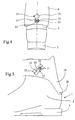
- Figure 4 is a back view of the second mode execution.
- Figure 5 is a side view of the third mode execution.
- the ski boot partially shown in Figures 1 to 3, essentially comprises a shell 1, forming a rod 2 surrounding the foot and the ankle at level of the malleoli and a sole 3, and a collar of lower leg 4 articulated on the shell 1 at the level of malleoli at two opposite points 5.
- the collar 4 is retained against rear tilting by a blade flexible 6, for example steel, curved downwards and retained by its ends in two housings 7 and 8 collar 4 which has a cutout at the back concave 9 extending above the blade 6.
- rod 2 has a bearing surface 10 at middle of which is formed a stop in the form of boss 11 coming into contact with the middle of the blade 6.
- the retaining means are in a first state stable.
- the rod 2 is provided with a stud 12 protruding above of blade 6.
- This stud 12 makes it possible to bring the blade 6 in its first stable state, FIG. 1, by the simple bending of the leg: in the position shown in Figure 3, the blade 6 comes indeed abut against the stud 12 during this bending.
- This embodiment also has the advantage of allow the trigger resistance to be adapted to the user morphology by an adequate choice of the blade 6.
- the back of the rod 2 is provided with an oval stud 13 and the collar has an oblong cutout 14 in which is engaged the stud 13.
- the cutout 14 is oriented substantially vertically and has two parts 15 to 16 of dimensions such that the stud 13 can be there housed in all its angular positions with a low clearance. These two parts 15 and 16 are connected by a narrowing 17 of width less than the most large transverse dimension of the stud 13.
- the stud 13 is provided with a screw slot 18 allowing its rotational drive by means of a piece of change.
- the stud 13 In the descent position, the stud 13 is engaged in the lower part 15 of the cutout 14. It occupies the angular position shown in the drawing.
- the collar 4 is retained in position by the stud 13 which abuts against the narrowing 17. If this effort exceeds the determined value, the pad 13 crosses the narrowing 17 while deforming elastically the plastic of the collar 4. There are trigger.
- the stud 13 could present pairs of facets defining different stud widths. At least two pairs of facets have distances, between facets, greater than the width of the narrowing 15. According to the orientation of the stud, the resistance to its passage to through the narrowing 17 will be more or less high.
- FIG. 5 shows the execution shoe. is fitted with a lower leg collar 19 hinged in 20 behind the rod 2.
- the collar is retained against tilting backwards by a stud 21, similar to stud 13, secured to rod 2, on the side of this rod, and engaged in an oblong cut 22 formed in a plate 23, made of metal or plastic fixed obliquely on the collar 19.
- the cutout 22 present, similar to the cutout 14, two parts 24 and 25 of substantially dimensions equal to those of stud 21 and connected by a narrowing 26 of width less than large dimension of the stud 21.
- the cutting 14 could also be formed in a wafer similar to the wafer 23.
- the cutout 22 could be formed in the plastic of the collar.
Landscapes
- Health & Medical Sciences (AREA)
- General Health & Medical Sciences (AREA)
- Physical Education & Sports Medicine (AREA)
- Footwear And Its Accessory, Manufacturing Method And Apparatuses (AREA)
Claims (7)
- Schischuh mit einem ersten Teil (1), das im wesentlichen aus einer Sohle (3) und einem den Fuss und den Knöchelbereich umgebenden Schaft (2) besteht, mit einem zweiten Teil, das aus einer Unterschenkelmanschette (4; 19) besteht, die in bezug auf den Schaft derart gelenkig ist, dass sie sich von vorn nach hinten und umgekehrt bewegen kann, und mit Mitteln zum Halten der Manschette, welche einem Kippen dieser Manschette nach hinten entgegenwirken, jedoch nachgeben, wenn die die Manschette zu kippen suchende Kraft einen bestimmten Wert übersteigt, dadurch gekennzeichnet, dass die erwähnten Haltemittel bistabile elastische Mittel sind, welche aus einem fest an einem Teil des Schuhs angebrachten Anschlag (13; 21) und aus einem elastisch verformbaren Stück (6; 4; 23 bestehen, das am anderen Teil des Schuhs befestigt und dazu bestimmt ist, durch den erwähnten Anschlag verformt zu werden.
- Schischuh nach Anspruch 1,dadurch gekennzeichnet, dass das elastisch verformbare Stück (6) eine gewölbte flexible Lamelle (6) ist, welche mit ihren Enden in einem der Teile des Schuhs derart eingespannt ist, dass die ein bistabiles Stück bildet.
- Schischuh nach Anspruch 1, dadurch gekennzeichnet, dass der Anschlag aus einem am Schaft befestigten Klotz (13) besteht, dass das bistabile Stück aus der Manschette (4) selber besteht, in welche ein länglicher Ausschnitt (14) gebildet ist, in den der erwähnte Klotz eingreift, und dass dieser Ausschnitt im wesentlichen senkrecht zu einem durch die Gelenkachse der Manschette verlaufenden Radius orientiert ist und zwei Teile (15, 16) aufweist, deren Abmessungen wenigstens gleich den Abmessungen des erwähnten Klotzes sind und welche durch eine Verengung (17) miteinander verbunden sind, deren Breite kleiner als wenigstens die grösste Querabmessung des Klotzes ist, derart, dass sich diese Verengung dem Durchgang des Klotzes widersetzt, wobei das Durchqueren der Verengung durch den Klotz durch Verformung der Manschette erfolgt.
- Schischuh nach Anspruch 1, dadurch gekennzeichnet, dass der Anschlag aus einem am Schaft befestigten Klotz (21) besteht, dass das bistabile Stück aus einem auf der Manschette befestigten aufgesetzten Stück (23) besteht, welches einen länglichen Ausschnitt (22) hat, in den der erwähnte Klotz (21) eingreift, und dass dieser Ausschnitt im wesentlichen senkrecht zu einem durch die Drehachse der Manschette verlaufenden Radius orientiert ist und zwei Teile (24, 25) hat, deren Abmessungen wenigstens gleich den Abmessungen des Klotzes (21) sind und welche durch eine Verengung miteinander verbunden sind, deren Breite kleiner als wenigstens die grösste Querabmessung des Klotzes ist, derart, dass sich diese Verengung dem Durchgang des Klotzes widersetzt, wobei das Durchqueren der Verengung durch den Klotz durch Verformung des aufgebrachten Stücks (23) erfolgt.
- Schischuh nach Anspruch 3 oder 4, dadurch gekennzeichnet, dass der Klotz (13; 21) wenigstens zwei Paare von paarweise parallelen Facetten hat, deren Abstände für jedes Paar verschieden und grösser als die Breite der Verengung (17; 26) sind.
- Schischuh nach einem der Ansprüche 3 bis 5, dadurch gekennzeichnet, dass der erwähnte Klotz (13; 21 eine Querabmessung hat, die kleiner als die Breite der erwähnten Verengung (17; 26) ist.
- Schischuh nach Anspruch 4, dadurch gekennzeichnet, dass das Plättchen nach dem Belieben des Benutzers gewechselt werden kann.
Applications Claiming Priority (2)
| Application Number | Priority Date | Filing Date | Title |
|---|---|---|---|
| CH01435/98A CH692233A5 (fr) | 1998-07-03 | 1998-07-03 | Chaussure de ski. |
| CH143598 | 1998-07-03 |
Publications (2)
| Publication Number | Publication Date |
|---|---|
| EP0968666A1 EP0968666A1 (de) | 2000-01-05 |
| EP0968666B1 true EP0968666B1 (de) | 2002-10-02 |
Family
ID=4210406
Family Applications (1)
| Application Number | Title | Priority Date | Filing Date |
|---|---|---|---|
| EP99810510A Expired - Lifetime EP0968666B1 (de) | 1998-07-03 | 1999-06-10 | Skischuh |
Country Status (4)
| Country | Link |
|---|---|
| US (1) | US6295745B1 (de) |
| EP (1) | EP0968666B1 (de) |
| CH (1) | CH692233A5 (de) |
| DE (1) | DE69903222T2 (de) |
Families Citing this family (3)
| Publication number | Priority date | Publication date | Assignee | Title |
|---|---|---|---|---|
| DE20118134U1 (de) * | 2001-11-07 | 2002-03-14 | Neumeyer, Max, 64289 Darmstadt | Schließmechanismus für Schuhe |
| EP3165113B1 (de) * | 2011-09-15 | 2022-03-16 | NB NewBoots SA | Sportstiefel |
| US9241532B2 (en) | 2012-01-04 | 2016-01-26 | K-2 Corporation | Ski/walk mechanism |
Family Cites Families (11)
| Publication number | Priority date | Publication date | Assignee | Title |
|---|---|---|---|---|
| US4360979A (en) * | 1978-03-15 | 1982-11-30 | Spademan Richard George | Sport shoe with a dynamic adjustable cuff assembly |
| FR2498061B1 (fr) * | 1981-01-20 | 1985-05-31 | Articles Sport Cie Fse | Chaussure de ski |
| CH645001A5 (fr) * | 1982-01-22 | 1984-09-14 | Battelle Memorial Institute | Chaussure de ski. |
| CH669718A5 (de) * | 1986-06-06 | 1989-04-14 | Lange Int Sa | |
| CH678385A5 (de) * | 1989-01-27 | 1991-09-13 | Lange Int Sa | |
| FR2656989B1 (fr) * | 1990-01-18 | 1992-04-24 | Salomon Sa | Chaussure de ski alpin du type a "entree arriere". |
| US5107608A (en) | 1990-10-02 | 1992-04-28 | Arthur Kreitenberg | Safety releasing ski boot |
| FR2678490B1 (fr) * | 1991-07-01 | 1993-09-24 | Salomon Sa | Chaussure de ski avec dispositif de blocage de tige. |
| FR2697728B1 (fr) | 1992-11-06 | 1995-01-13 | Salomon Sa | Chaussure destinée à la pratique d'un sport de glisse. |
| WO1997022271A1 (en) | 1995-12-19 | 1997-06-26 | Lange International S.A. | Injury preventing ski boot |
| FR2752147B1 (fr) * | 1996-08-06 | 1998-10-09 | Salomon Sa | Chaussure de sport |
-
1998
- 1998-07-03 CH CH01435/98A patent/CH692233A5/fr not_active IP Right Cessation
-
1999
- 1999-06-10 DE DE69903222T patent/DE69903222T2/de not_active Expired - Fee Related
- 1999-06-10 EP EP99810510A patent/EP0968666B1/de not_active Expired - Lifetime
- 1999-06-14 US US09/332,696 patent/US6295745B1/en not_active Expired - Fee Related
Also Published As
| Publication number | Publication date |
|---|---|
| DE69903222D1 (de) | 2002-11-07 |
| US6295745B1 (en) | 2001-10-02 |
| EP0968666A1 (de) | 2000-01-05 |
| DE69903222T2 (de) | 2003-07-10 |
| CH692233A5 (fr) | 2002-04-15 |
Similar Documents
| Publication | Publication Date | Title |
|---|---|---|
| EP0248149B1 (de) | Schischuh | |
| EP2674203A1 (de) | Zehenhalter mit automatischer Auslösung in Torsion | |
| CH645001A5 (fr) | Chaussure de ski. | |
| EP0825892B1 (de) | Schuhbindungsvorrichtung für einen gleitschuh | |
| CH668888A5 (fr) | Chaussure de ski. | |
| EP0968664B1 (de) | Skischuh | |
| FR2788444A1 (fr) | Fixation declenchable pour planche de glisse | |
| EP1104251B1 (de) | Langlaufskischuh | |
| EP0968666A1 (de) | Skischuh | |
| FR2745192A1 (fr) | Dispositif de retenue d'une chaussure sur une planche de glisse. | |
| EP0968665B1 (de) | Skischuh | |
| FR2666201A1 (fr) | Chaussure de sport, notamment pour la pratique du ski de fond. | |
| WO1997018016A1 (fr) | Dispositif de retenue d'une chaussure de snowboard permettant un basculement lateral de la chaussure par rapport a la planche | |
| EP2259851B1 (de) | Bremssystem für inlineskates | |
| EP1785172B1 (de) | Sportschuh-Bindungsvorrichtung auf einem Gleitbrett | |
| EP0667174A1 (de) | Sicherheitsbindung für Skier mit Ausgleichsvorrichtung | |
| EP4670549A1 (de) | Verriegelungsvorrichtung für einen skischuh | |
| FR3072884A1 (fr) | Butee de dispositif de fixation d'une chaussure | |
| EP2379183A1 (de) | Schneeschuh mit einer kletterleiste | |
| FR2543445A1 (fr) | Fixation de securite pour ski | |
| EP1138354B1 (de) | Vorrichtung zur Halterung eines Schuhvorderteils auf einem Ski | |
| FR2666748A1 (fr) | Fixation de securite pour ski. | |
| EP4555889A1 (de) | Verriegelungsvorrichtung für einen sportschuh | |
| CH673777A5 (de) | ||
| FR2788443A1 (fr) | Fixation declenchable pour planche de glisse |
Legal Events
| Date | Code | Title | Description |
|---|---|---|---|
| PUAI | Public reference made under article 153(3) epc to a published international application that has entered the european phase |
Free format text: ORIGINAL CODE: 0009012 |
|
| AK | Designated contracting states |
Kind code of ref document: A1 Designated state(s): DE FR IT |
|
| AX | Request for extension of the european patent |
Free format text: AL;LT;LV;MK;RO;SI |
|
| 17P | Request for examination filed |
Effective date: 20000413 |
|
| AKX | Designation fees paid |
Free format text: DE FR IT |
|
| GRAG | Despatch of communication of intention to grant |
Free format text: ORIGINAL CODE: EPIDOS AGRA |
|
| 17Q | First examination report despatched |
Effective date: 20020208 |
|
| GRAG | Despatch of communication of intention to grant |
Free format text: ORIGINAL CODE: EPIDOS AGRA |
|
| GRAH | Despatch of communication of intention to grant a patent |
Free format text: ORIGINAL CODE: EPIDOS IGRA |
|
| GRAH | Despatch of communication of intention to grant a patent |
Free format text: ORIGINAL CODE: EPIDOS IGRA |
|
| GRAA | (expected) grant |
Free format text: ORIGINAL CODE: 0009210 |
|
| AK | Designated contracting states |
Kind code of ref document: B1 Designated state(s): DE FR IT |
|
| REF | Corresponds to: |
Ref document number: 69903222 Country of ref document: DE Date of ref document: 20021107 |
|
| PLBE | No opposition filed within time limit |
Free format text: ORIGINAL CODE: 0009261 |
|
| STAA | Information on the status of an ep patent application or granted ep patent |
Free format text: STATUS: NO OPPOSITION FILED WITHIN TIME LIMIT |
|
| 26N | No opposition filed |
Effective date: 20030703 |
|
| PGFP | Annual fee paid to national office [announced via postgrant information from national office to epo] |
Ref country code: DE Payment date: 20050628 Year of fee payment: 7 |
|
| PGFP | Annual fee paid to national office [announced via postgrant information from national office to epo] |
Ref country code: FR Payment date: 20060616 Year of fee payment: 8 |
|
| PGFP | Annual fee paid to national office [announced via postgrant information from national office to epo] |
Ref country code: IT Payment date: 20060630 Year of fee payment: 8 |
|
| PG25 | Lapsed in a contracting state [announced via postgrant information from national office to epo] |
Ref country code: DE Free format text: LAPSE BECAUSE OF NON-PAYMENT OF DUE FEES Effective date: 20070103 |
|
| REG | Reference to a national code |
Ref country code: FR Ref legal event code: ST Effective date: 20080229 |
|
| PG25 | Lapsed in a contracting state [announced via postgrant information from national office to epo] |
Ref country code: FR Free format text: LAPSE BECAUSE OF NON-PAYMENT OF DUE FEES Effective date: 20070702 |
|
| PG25 | Lapsed in a contracting state [announced via postgrant information from national office to epo] |
Ref country code: IT Free format text: LAPSE BECAUSE OF NON-PAYMENT OF DUE FEES Effective date: 20070610 |