EP0969228A2 - Vis à billes - Google Patents
Vis à billes Download PDFInfo
- Publication number
- EP0969228A2 EP0969228A2 EP99305111A EP99305111A EP0969228A2 EP 0969228 A2 EP0969228 A2 EP 0969228A2 EP 99305111 A EP99305111 A EP 99305111A EP 99305111 A EP99305111 A EP 99305111A EP 0969228 A2 EP0969228 A2 EP 0969228A2
- Authority
- EP
- European Patent Office
- Prior art keywords
- ball
- ballscrew
- cage
- screw shaft
- balls
- Prior art date
- Legal status (The legal status is an assumption and is not a legal conclusion. Google has not performed a legal analysis and makes no representation as to the accuracy of the status listed.)
- Withdrawn
Links
Images


Classifications
-
- F—MECHANICAL ENGINEERING; LIGHTING; HEATING; WEAPONS; BLASTING
- F16—ENGINEERING ELEMENTS AND UNITS; GENERAL MEASURES FOR PRODUCING AND MAINTAINING EFFECTIVE FUNCTIONING OF MACHINES OR INSTALLATIONS; THERMAL INSULATION IN GENERAL
- F16H—GEARING
- F16H25/00—Gearings comprising primarily only cams, cam-followers and screw-and-nut mechanisms
- F16H25/18—Gearings comprising primarily only cams, cam-followers and screw-and-nut mechanisms for conveying or interconverting oscillating or reciprocating motions
- F16H25/20—Screw mechanisms
- F16H25/22—Screw mechanisms with balls, rollers, or similar members between the co-operating parts; Elements essential to the use of such members
- F16H25/2204—Screw mechanisms with balls, rollers, or similar members between the co-operating parts; Elements essential to the use of such members with balls
- F16H25/2233—Screw mechanisms with balls, rollers, or similar members between the co-operating parts; Elements essential to the use of such members with balls with cages or means to hold the balls in position
Definitions
- the present invention relates to a ballscrew.
- a ball nut with an internal helical groove surrounds a screw shaft, around which is formed an external helical groove, these grooves being of the same pitch so that, when the ballscrew is assembled, the two grooves define a cavity which is helical in shape and has a generally circular cross-section.
- Ball bearings having a diameter just slightly less than the cross-section of the helical cavity fill the latter at a certain section or sections along the ballscrew.
- the balls roll within the helical cavity against the ball nut and the screw shaft so that the ballscrew can act as a rotary bearing, the nut and shaft moving axially relative to one another as a result of their relative rotary motion.
- the present invention seeks to provide a remedy.
- the present invention is directed to a ballscrew having a ball cage interposed between the ball nut and the screw shaft.
- the ball cage is cylindrical. Slots may be formed in it extending in an axial direction to accommodate the balls.
- each slot is slightly less than the diameter of each ball and the cross-sectional diameter of the ball cage is such that more than half of each ball projects outwardly of the cage to facilitate recirculation of the balls.
- a spring may be secured between the ball cage and the screw shaft, or between the ball cage and the ball nut, to urge the ball cage into a normal position. This reduces the extent to which the balls are free to migrate from a normal position along the screw shaft.
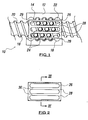
- the ballscrew 10 shown in Figure 1 comprises a ball nut 12 made of a hollow cylinder of metal or synthetic plastics material and having a generally cylindrical inner surface 14 on which is formed an internal helical groove 16.
- a screw shaft 18 extends through the ball nut 12 coaxially therewith, and is formed with an internal helical groove 20 having the same pitch as the groove 16 of the ball nut 12.
- the grooves 16 and 20 thereby define a helical cavity 22 between the ball nut 12 and the screw shaft 18, which is generally circular in cross-section.
- a multiplicity of balls 234 are uniformed spaced apart within this helical cavity 22.
- the balls 24 may be metal ball bearings or they may be made of a synthetic plastics material.
- a cylindrical machined metal or synthetic plastics integrally moulded ball cage 26 is interposed between the ball nut 12 and the screw shaft 18 so as to be coaxial therewith. It is provided with elongate slots 28 extending in an axial direction and having a width which is slightly less than the diameter of each ball 24, so that more than half of each ball is outside the cage 26.
- the ball cage 26 may be retained in the ball nut 12 by means of inwardly directed lips 29 at each end of the nut 12.
- One of the lips 29 may be removable for assembly and dismantling of the ballscrew.
- the cage 26 is shown on its own in Figures 2 and 3.
- the strips 30 of cage material between the slots 28 therefore act as spacers between the balls 24, and prevent the latter contacting one another whilst rolling around the screw shaft 18.
- Figure 5 shows an internal edge of one of the slots 28. This is seen to be arcuate, so that it corresponds to the surface of each ball 24. However, this arcuate edge of each strip 30 is uniform along the length of the strip to enable the balls to shift along the associated slot 28 as it progresses along the screw shaft 18, in an axial direction equal to at least one, and in this case four turns of the helical cavity 22.
- the screw shaft 18 rotates within the ball nut 12
- the angular velocity of the balls 24 and the cage 26 will be generally half the angular velocity of the screw shaft 18 by virtue of the rolling motion of the balls 24 against the ball nut 12 and the screw shaft 18.
- Figure 6 shows means for recirculating the balls 24, for example to enable the ball nut 12 to progress along the screw shaft 18 at a distance which is substantially greater than the axial extent of the ball nut.
- the parts concerned are shown in ghosted form since they overlap one another.
- a scoop 32 on the internal surface of the ball nut 12 is positioned in the path of the balls 24 so that when each ball 24 reaches the scoop 32, it is lifted out of the groove 20 and the relevant slot 28 up into a recirculating passageway 34 within the ball nut 12.
- the ball which has just been lifted in this way is then urged further into the passageway 34 by the next ball arriving into the scoop 32 as the screw shaft rotates relative to the ball nut 12.
- the chute 36 becomes the scoop and the scoop 32 becomes the chute.
- the recirculation passageway 34 is shown as an S-shape, it could clearly be any shape, and may for example be helical following the material of the ball nut 12 around the ball screw 18 at an angle of 45° to the ballscrew axis.
- a spiral spring 70 has one end 72 secured to the centre of one end of the shaft 18 and another end 74 secured to one end of the ball cage 26.
- each slot 28 at the cage 26 is half the maximum possible axial displacement of the balls along the screw shaft.
- the cage 26 and slots 28 may be so dimensioned that more than half of each ball is on the inside of the cage 26, in which case it would be possible for the balls 24 to be retained on the screw shaft 18 even in the absence of the ball nut 12, to facilitate assembly and dismantling of the ballscrew.
Landscapes
- Engineering & Computer Science (AREA)
- General Engineering & Computer Science (AREA)
- Mechanical Engineering (AREA)
- Transmission Devices (AREA)
Applications Claiming Priority (2)
| Application Number | Priority Date | Filing Date | Title |
|---|---|---|---|
| GB9814164 | 1998-06-30 | ||
| GBGB9814164.1A GB9814164D0 (en) | 1998-06-30 | 1998-06-30 | Ballscrew |
Publications (2)
| Publication Number | Publication Date |
|---|---|
| EP0969228A2 true EP0969228A2 (fr) | 2000-01-05 |
| EP0969228A3 EP0969228A3 (fr) | 2001-01-03 |
Family
ID=10834695
Family Applications (1)
| Application Number | Title | Priority Date | Filing Date |
|---|---|---|---|
| EP99305111A Withdrawn EP0969228A3 (fr) | 1998-06-30 | 1999-06-29 | Vis à billes |
Country Status (2)
| Country | Link |
|---|---|
| EP (1) | EP0969228A3 (fr) |
| GB (1) | GB9814164D0 (fr) |
Cited By (4)
| Publication number | Priority date | Publication date | Assignee | Title |
|---|---|---|---|---|
| US6898994B2 (en) * | 2000-03-03 | 2005-05-31 | Thomson Saginaw Ball Screw Company, Llc | Ball nut and screw assembly |
| DE102007010327A1 (de) * | 2007-03-02 | 2008-09-25 | Knorr-Bremse Systeme für Nutzfahrzeuge GmbH | Zuspannvorrichtung für eine elektromechanisch oder elektrohydraulisch betätigbare Fahrzeug-Scheibenbremse |
| FR3067779A1 (fr) * | 2017-06-14 | 2018-12-21 | Valeo Systemes De Controle Moteur | Dispositif d'actionnement pour actionneur de controle moteur, comprenant un mecanisme de vis a billes avec cage |
| CN112196921A (zh) * | 2019-07-07 | 2021-01-08 | 瀚德刹车片产品公司 | 制动器致动机构和盘式制动器以及制造方法 |
Family Cites Families (4)
| Publication number | Priority date | Publication date | Assignee | Title |
|---|---|---|---|---|
| IT1070470B (it) * | 1975-10-28 | 1985-03-29 | Arnold Franz | Meccanismo a vite a sfere |
| US4229983A (en) * | 1978-03-29 | 1980-10-28 | France Bed Co., Ltd. | Ball-and-screw power transmission device |
| JPS56120851A (en) * | 1980-02-29 | 1981-09-22 | Hiroshi Teramachi | Ball screw with retainer |
| JPS6078155A (ja) * | 1983-09-30 | 1985-05-02 | Toshiba Corp | 減速機 |
-
1998
- 1998-06-30 GB GBGB9814164.1A patent/GB9814164D0/en not_active Ceased
-
1999
- 1999-06-29 EP EP99305111A patent/EP0969228A3/fr not_active Withdrawn
Cited By (5)
| Publication number | Priority date | Publication date | Assignee | Title |
|---|---|---|---|---|
| US6898994B2 (en) * | 2000-03-03 | 2005-05-31 | Thomson Saginaw Ball Screw Company, Llc | Ball nut and screw assembly |
| DE102007010327A1 (de) * | 2007-03-02 | 2008-09-25 | Knorr-Bremse Systeme für Nutzfahrzeuge GmbH | Zuspannvorrichtung für eine elektromechanisch oder elektrohydraulisch betätigbare Fahrzeug-Scheibenbremse |
| DE102007010327B4 (de) * | 2007-03-02 | 2019-10-24 | Knorr-Bremse Systeme für Nutzfahrzeuge GmbH | Zuspannvorrichtung für eine elektromechanisch oder elektrohydraulisch betätigbare Fahrzeug-Scheibenbremse |
| FR3067779A1 (fr) * | 2017-06-14 | 2018-12-21 | Valeo Systemes De Controle Moteur | Dispositif d'actionnement pour actionneur de controle moteur, comprenant un mecanisme de vis a billes avec cage |
| CN112196921A (zh) * | 2019-07-07 | 2021-01-08 | 瀚德刹车片产品公司 | 制动器致动机构和盘式制动器以及制造方法 |
Also Published As
| Publication number | Publication date |
|---|---|
| GB9814164D0 (en) | 1998-08-26 |
| EP0969228A3 (fr) | 2001-01-03 |
Similar Documents
| Publication | Publication Date | Title |
|---|---|---|
| KR100953461B1 (ko) | 순환 부재, 이 순환 부재를 구비한 운동 안내 장치 및 이순환 부재를 구비한 볼 나사 | |
| US6619845B2 (en) | Roller retainer, direct-acting guide device and roller screw using the roller retainer | |
| JP2000120825A (ja) | ボ―ルねじ機構、および直動装置 | |
| US6282971B1 (en) | Ball screw | |
| KR930010902B1 (ko) | 볼 나사 | |
| US3055230A (en) | Screw-nut assemblies | |
| DE10121311B4 (de) | Wälzkörper-Abstandshalter in einer Rollführungsvorrichtung | |
| US6776063B2 (en) | Ball screw | |
| CN101410652A (zh) | 滚珠丝杠装置 | |
| JPH11210858A (ja) | 循環式ねじ装置 | |
| EP0969228A2 (fr) | Vis à billes | |
| EP0281491B1 (fr) | Système comprenant une broche à circulation de billes et un écrou ouvert associé, utilisé pour supporter des broches filetées | |
| JP5178889B2 (ja) | ボールねじ | |
| US2714821A (en) | Deflector pin construction for ballbearing screw and nut mechanism | |
| US8272289B2 (en) | Roller screw | |
| DE4318427C2 (de) | Wälzkörperumlauflager | |
| KR102269699B1 (ko) | 볼 나사 | |
| US5520038A (en) | Device for manufacturing a groove bearing | |
| DE4327543C2 (de) | Gleit-Wälz-Lager | |
| EP1245868B1 (fr) | Mécanisme de vis à billes | |
| EP1347187A2 (fr) | Palier linéaire | |
| US20200362946A1 (en) | Everted Ball Screw Drive | |
| KR20210002561A (ko) | 볼 나사 | |
| KR20070059976A (ko) | 베어링 스크류 이송장치 | |
| KR100657657B1 (ko) | 베어링 스크류 이송장치 |
Legal Events
| Date | Code | Title | Description |
|---|---|---|---|
| PUAI | Public reference made under article 153(3) epc to a published international application that has entered the european phase |
Free format text: ORIGINAL CODE: 0009012 |
|
| AK | Designated contracting states |
Kind code of ref document: A2 Designated state(s): AT BE CH CY DE DK ES FI FR GB GR IE IT LI LU MC NL PT SE |
|
| AX | Request for extension of the european patent |
Free format text: AL;LT;LV;MK;RO;SI |
|
| PUAL | Search report despatched |
Free format text: ORIGINAL CODE: 0009013 |
|
| AK | Designated contracting states |
Kind code of ref document: A3 Designated state(s): AT BE CH CY DE DK ES FI FR GB GR IE IT LI LU MC NL PT SE |
|
| AX | Request for extension of the european patent |
Free format text: AL;LT;LV;MK;RO;SI |
|
| AKX | Designation fees paid | ||
| STAA | Information on the status of an ep patent application or granted ep patent |
Free format text: STATUS: THE APPLICATION IS DEEMED TO BE WITHDRAWN |
|
| 18D | Application deemed to be withdrawn |
Effective date: 20010704 |