EP0970876B1 - Système de détection d'angle de dérapage de roue d'un véhicule - Google Patents
Système de détection d'angle de dérapage de roue d'un véhicule Download PDFInfo
- Publication number
- EP0970876B1 EP0970876B1 EP99113360A EP99113360A EP0970876B1 EP 0970876 B1 EP0970876 B1 EP 0970876B1 EP 99113360 A EP99113360 A EP 99113360A EP 99113360 A EP99113360 A EP 99113360A EP 0970876 B1 EP0970876 B1 EP 0970876B1
- Authority
- EP
- European Patent Office
- Prior art keywords
- slip angle
- lateral
- vehicle
- lateral acceleration
- detecting
- Prior art date
- Legal status (The legal status is an assumption and is not a legal conclusion. Google has not performed a legal analysis and makes no representation as to the accuracy of the status listed.)
- Expired - Lifetime
Links
Images


Classifications
-
- B—PERFORMING OPERATIONS; TRANSPORTING
- B60—VEHICLES IN GENERAL
- B60W—CONJOINT CONTROL OF VEHICLE SUB-UNITS OF DIFFERENT TYPE OR DIFFERENT FUNCTION; CONTROL SYSTEMS SPECIALLY ADAPTED FOR HYBRID VEHICLES; ROAD VEHICLE DRIVE CONTROL SYSTEMS FOR PURPOSES NOT RELATED TO THE CONTROL OF A PARTICULAR SUB-UNIT
- B60W40/00—Estimation or calculation of non-directly measurable driving parameters for road vehicle drive control systems not related to the control of a particular sub unit, e.g. by using mathematical models
- B60W40/10—Estimation or calculation of non-directly measurable driving parameters for road vehicle drive control systems not related to the control of a particular sub unit, e.g. by using mathematical models related to vehicle motion
- B60W40/101—Side slip angle of tyre
-
- B—PERFORMING OPERATIONS; TRANSPORTING
- B60—VEHICLES IN GENERAL
- B60T—VEHICLE BRAKE CONTROL SYSTEMS OR PARTS THEREOF; BRAKE CONTROL SYSTEMS OR PARTS THEREOF, IN GENERAL; ARRANGEMENT OF BRAKING ELEMENTS ON VEHICLES IN GENERAL; PORTABLE DEVICES FOR PREVENTING UNWANTED MOVEMENT OF VEHICLES; VEHICLE MODIFICATIONS TO FACILITATE COOLING OF BRAKES
- B60T8/00—Arrangements for adjusting wheel-braking force to meet varying vehicular or ground-surface conditions, e.g. limiting or varying distribution of braking force
- B60T8/17—Using electrical or electronic regulation means to control braking
- B60T8/1755—Brake regulation specially adapted to control the stability of the vehicle, e.g. taking into account yaw rate or transverse acceleration in a curve
- B60T8/17551—Brake regulation specially adapted to control the stability of the vehicle, e.g. taking into account yaw rate or transverse acceleration in a curve determining control parameters related to vehicle stability used in the regulation, e.g. by calculations involving measured or detected parameters
-
- B—PERFORMING OPERATIONS; TRANSPORTING
- B62—LAND VEHICLES FOR TRAVELLING OTHERWISE THAN ON RAILS
- B62D—MOTOR VEHICLES; TRAILERS
- B62D6/00—Arrangements for automatically controlling steering depending on driving conditions sensed and responded to, e.g. control circuits
- B62D6/04—Arrangements for automatically controlling steering depending on driving conditions sensed and responded to, e.g. control circuits responsive only to forces disturbing the intended course of the vehicle, e.g. forces acting transversely to the direction of vehicle travel
-
- B—PERFORMING OPERATIONS; TRANSPORTING
- B60—VEHICLES IN GENERAL
- B60T—VEHICLE BRAKE CONTROL SYSTEMS OR PARTS THEREOF; BRAKE CONTROL SYSTEMS OR PARTS THEREOF, IN GENERAL; ARRANGEMENT OF BRAKING ELEMENTS ON VEHICLES IN GENERAL; PORTABLE DEVICES FOR PREVENTING UNWANTED MOVEMENT OF VEHICLES; VEHICLE MODIFICATIONS TO FACILITATE COOLING OF BRAKES
- B60T2230/00—Monitoring, detecting special vehicle behaviour; Counteracting thereof
- B60T2230/02—Side slip angle, attitude angle, floating angle, drift angle
Definitions
- the present invention relates to a wheel slip angle detecting system for a vehicle according to the preamble part of claim 1.
- Such a wheel slip angle detecting system is known from EP 0 775 617 A, a family member of JP 9 142286 A. From this document there is known a technique of detecting a slip angle of each of wheels in the control of the motion of a vehicle (e.g., in the traction control, the antilock brake control and the like).
- a lateral slip angle of a vehicle body (an angle formed by the direction of movement of the vehicle with respect to the orientation of the vehicle) must be calculated. It is a conventional practice to calculate a lateral slip angle ⁇ of a vehicle body by integrating a differentiated value of lateral slip angle determined according to a differential equation based on a linear two-wheel vehicle's motion model.
- a sensor noise (a mounting error noise) of detector means for detecting a lateral acceleration AY, a yaw rate ⁇ and a vehicle speed V and a travel noise are accumulated in the course of integral calculation, resulting in poor lateral slip angle calculation accuracy and in reduced wheel slip angle detecting accuracy.
- a wheel slip angle detecting system for a vehicle of the generic kind, wherein a lateral slip angle of a vehicle body is calculated with good accuracy using an appropriate calculating equation suitable for a travel state of the vehicle, and a wheel slip angle is determined with good accuracy using the lateral slip angle having high accuracy.
- a wheel slip angle detecting system with all features of claim 1.
- This system is designed to determine a slip angle of each of wheels (an angle formed by the direction of movement of the wheel with respect to the orientation of the wheel) to grasp a road surface contact situation of each wheel, and more specifically, a lateral force itself of each wheel, in order to increase the accuracy in the control of the motion, e.g., of the turning movement of the vehicle.
- a wheel slip angle detecting system for a vehicle comprising a vehicle speed detecting means for detecting a vehicle speed; a yaw rate detecting means for detecting a yaw rate, a lateral acceleration detecting means for detecting a lateral acceleration; a steering angle detecting means for detecting a steering angle; a slip rate calculating means for calculating a slip rate of each of wheels; a tire characteristic establishing means in which tire characteristics are previously determined based on actual travel data; a travel-state detecting means for detecting a travel state of the vehicle based on the vehicle speed, the yaw rate, the lateral acceleration and the steering angle which are detected by the detecting means, respectively; a lateral acceleration presuming means for determining a presumed lateral acceleration of a vehicle body; a first lateral slip angle calculating means for calculating a lateral slip angle of the vehicle body as a first lateral slip angle by integrating a differentiated value of lateral
- linear two-wheel vehicle's motion model means a motion model in which cornering forces for the front and rear wheels are varied linearly with respect to the slip angle on the assumption that the cornering forces for the left and right front wheels are equal to each other and the cornering forces for the left and right rear wheels are equal to each other.
- non-linear four-wheel vehicle's motion model means a motion model in which cornering forces for the front and rear wheels are varied non-linearly with respect to the slip angle in a state in which it is not on the assumption that the cornering forces for the left and right front wheels and for the left and right rear wheels are equal to each other.
- the slip angle of each wheel is calculated based on the second lateral slip angle calculated in the second lateral slip angle calculating means.
- the second lateral slip angle is calculated using detected values of the vehicle speed, yaw rate, lateral acceleration and steering angle and is not calculated by integration. Therefore, even if the detected values of the vehicle speed, yaw rate, lateral acceleration and steering angle are small due to a low-speed traveling state near a state traveling straightforwardly, a sensor noise (a mounting error noise) and a travel noise cannot be accumulated and hence, the lateral slip angle can be calculated with good accuracy.
- the slip angle of each wheel is calculated based on the first lateral slip angle calculated in the first lateral slip angle calculating means.
- the detected values of the vehicle speed and the yaw rate are relatively large, and the proportion of the noise magnitude with respect to the detected values is relatively small.
- the lateral acceleration is presumed using the tire characteristics previously established from actual travelings and at least one of the slip angle calculated in the slip angle calculating means and the slip rate calculated in the slip rate calculating means so that the presuming accuracy can be increased.
- the wheel slip angle can be determined with good accuracy based on the lateral slip angle of high accuracy, irrespective of the traveling state of the vehicle.
- the wheel slip angle detecting system further comprises a first deviation calculating means for calculating a deviation between the presumed lateral acceleration determined in the lateral acceleration presuming means and the lateral acceleration detected by the lateral acceleration detecting means based on the tire characteristics established in the tire characteristic establishing means, a vehicle body yaw moment presuming means for presuming a yaw rate variation speed as a vehicle body yaw moment based on the tire characteristics established in the tire characteristic establishing means, a differentiating means for differentiating the yaw rate detected by the yaw rate detecting means, a second deviation calculating means for calculating a deviation between the presumed yaw rate variation speed determined in the vehicle body yaw moment presuming means and a detected yaw rate variation speed determined in the differentiating means, a high-select means for selecting a larger one of the deviations calculated respectively in the first and second deviation calculating means,
- the wheel slip angle depending on an actual road surface friction coefficient. More specifically, the presumed lateral acceleration and the presumed yaw rate variation speed are based on the tire characteristics established in the tire characteristic establishing means with the road surface friction coefficient being defined constant.
- a larger one of the value calculated in the first deviation calculating means for calculating the deviation between the detected lateral acceleration and the presumed lateral acceleration and the value calculated in the second deviation calculating means for calculating the deviation between the detected yaw rate and the presumed yaw rate i.e., a value largely influenced by the variation in friction coefficient is a deviation corresponding to an amount of variation in friction coefficient, and the friction coefficient is corrected, while the presumed lateral acceleration and the presumed yaw rate variation speed are corrected.
- the tire characteristics can be corrected in accordance with the actual road surface friction coefficient, and further, a corrected precise wheel slip angle can be determined.
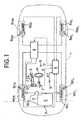
- a power unit P comprising an engine E and a transmission T is mounted at a front portion of a vehicle body 1 to drive a left front wheel W FL and a right front wheel W FR which are driven wheels.
- Left and right front wheel brakes B FL and B FR are mounted on the left and right front wheels W FL and W FR
- left and right rear wheel brakes B RL and B RR are mounted on a left rear wheel W RL and a right rear wheel W RR which are follower wheels.
- Each of the wheel brakes B FL , B FR , B RL and B RR is a disk brake, for example.
- a braking liquid pressure depending on the operation of depression of a brake pedal 3 is delivered from first and second output ports 2A and 2B provided in a tandem-type master cylinder M. Both of the output ports 2A and 2B are connected to a braking liquid pressure circuit 4, so that a braking liquid pressure from the braking liquid pressure circuit 4 is applied to each of the wheel brakes B FL , B FR , B RL and B RR .
- the braking liquid pressure applied to each of the wheel brakes B FL , B FR , B RL and B RR is regulated by control by a control unit 5.
- Input to the control unit 5 are detection values provided by wheel speed detectors 6 FL , 6 FR , 6 RL and 6 RR for detecting wheel speed of the wheels W FL , W FR , W RL and W RR , a steering angle detecting means 7 for detecting a steering angle ⁇ provided by operation of a steering wheel H, a yaw rate detecting means 8 for detecting a yaw rate ⁇ of a vehicle, and a lateral acceleration detecting means 9 for detecting a lateral acceleration AY of the vehicle.
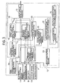
- the control unit 5 includes a vehicle speed detecting means 10, a slip rate calculating means 11, a wheel slip angle calculating section 12, and a braking amount control section 26.
- a vehicle speed V is provided based on the detection values provided by the four wheel speed detectors 6 FL , 6 FR , 6 RL and 6 RR for individually detecting wheel speed of the wheels W FL , W FR , W RL and W RR .
- the slip rate calculating means 11 a slip rate for every wheel is calculated based on the vehicle speed V calculated by the vehicle speed detecting means 10 and the detection values provided by the wheel speed detectors 6 FL , 6 FR , 6 RL and 6 RR .
- the wheel slip angle calculating section 12 calculates a slip angle of each of the wheels to grasp a grip force of each of tires on the four front and rear wheels in order to increase the control accuracy in the control of the turning movement of the vehicle.
- a slip angle ⁇ for every wheel is calculated in the wheel slip angle calculating section 12, based on the steering angle ⁇ detected by the steering angle detecting means 7, the yaw rate ⁇ detected by the yaw rate detecting means 8, the lateral acceleration AY detected by the lateral acceleration detecting means 9, the vehicle speed V detected by the vehicle speed detecting means 10, and the slip rate for every wheel calculated by the slip rate calculating means 11.
- the wheel slip angle ⁇ provided by the wheel slip angle calculating section 12 is input to the braking amount control section 26.
- the braking liquid pressure applied to each of the wheel brakes B FL , B FR, B RL and B RR to control the turning movement of the vehicle on the basis of the wheel slip angle is calculated in the braking amount control section 26.
- the braking liquid pressure circuit 4 is operated on the basis of the result of the calculation in the braking amount control section 26.
- the wheel slip angle calculating section 12 includes a travel-state detecting means 13, a tire characteristic establishing means 14, a lateral acceleration presuming means 15, a first lateral slip angle calculating means 16, a second lateral slip angle calculating means 17, a selecting means 18, a slip angle calculating means 19, a first deviation calculating means 20, a second deviation calculating means 21, a vehicle body yaw moment presuming means 22, a differentiating means 23, a high-select means 24, and a friction coefficient presuming means 25.
- Tire characteristics for every tire on the wheels are previously established in the tire characteristic determining means 14 based on actual travel data. Specifically, a slip angle/cornering force characteristic showing the relationship between the slip angle ⁇ and the cornering force CF, a slip angle/cornering force decrease rate characteristic showing the relationship between the slip rate ⁇ and the cornering force decrease rate RCF and a slip rate/braking and driving force characteristic showing the relationship between the slip rate ⁇ and the braking and driving forces FX, are previously established in the tire characteristic establishing means 14 for every wheel in accordance with the friction coefficient ⁇ of a road surface presumed by the friction coefficient presuming means 25, as shown in Fig.4.
- the tire characteristic establishing means 14 has a function to correct the slip angle/cornering force characteristic, the slip angle/cornering force decrease rate characteristic and the slip rate/braking and driving force characteristic in accordance with the presumed friction coefficient ⁇ provided by the friction coefficient presuming means 25.
- a presumed lateral acceleration AYE is presumed by the lateral acceleration presuming means 15, based on the slip angle/cornering force characteristic and the slip rate/cornering force decrease rate characteristic of the tire characteristics established in the tire characteristic establishing means 14. More specifically, the tire characteristic establishing means 14 is connected to the lateral acceleration presuming means 15, and the slip rate ⁇ calculated in the slip rate calculating means 11 and the slip angle ⁇ for every wheel calculated in the slip angle calculating means 19 are input to the lateral acceleration presuming means 15, so that the presumed lateral acceleration AYE is determined in the lateral acceleration presuming means 15, based on a total sum of values (CF x RCF) for the four left and right front and rear wheels.
- CF x RCF total sum of values
- the cornering force CF is corrected in accordance with a variation in the slip rate ⁇ with the control of the vehicle's motion by multiplying the cornering force CF by the cornering force decrease rate RCF based on the slip rate/cornering force decrease rate characteristic in the above calculation (CF x RCF).
- the presumed lateral acceleration AYE determined by the lateral acceleration presuming means 15 is input to the first lateral slip angle calculating means 16.
- the vehicle speed V detected by the vehicle speed detecting means 10 and the yaw rate ⁇ detected by the yaw rate detecting means 8, in addition to the presumed lateral acceleration AYE, are input to the first lateral slip angle calculating means 16, and the calculation for determining the lateral slip angle of the vehicle body as a first lateral slip angle ⁇ 1 based on a non-linear four-wheel vehicle's motion model is carried out in the first lateral slip angle calculating means 16.
- a differentiation value of a lateral slip angle is provided as ⁇ (lateral acceleration/vehicle speed) - yaw rate ⁇ .
- the lateral acceleration is the presumed lateral acceleration AYE;
- the vehicle speed is the vehicle speed V detected by the vehicle speed detecting means 10;
- the yaw rate is the yaw rate ⁇ detected by the yaw rate detecting means 8
- the first lateral slip angle ⁇ 1 determined based on the non-linear four-wheel vehicle's motion model is equal to a lateral slip angle at the time when the lateral slip amount is relatively large in the turning movement state of the vehicle.
- the lateral slip amount is relatively small in a state in which the vehicle is traveling straightforwardly at a low speed
- a wheel slip angle ⁇ is determined using the first lateral slip angle ⁇ 1 in the state in which the vehicle is traveling straightforwardly at the low speed. Therefore, the calculation for determining the lateral slip angle of the vehicle body as a second lateral slip angle ⁇ 2 based on a linear two-wheel vehicle's motion model is carried out in the second lateral slip angle calculating means 17.
- a lateral dynamic equation is used wherein the cornering forces CFF for the left and right front wheels are equal to each other, and the cornering forces CFR for the left and right rear wheels are each to each other, as shown in Fig.5.
- the slip angle ⁇ F of the front wheels and the slip angle ⁇ R of the rear wheels and the lateral slip angle ⁇ of the vehicle body are represented with the counterclockwise direction being defined as positive.
- the second lateral slip angle calculating means 17 carries out the calculation according to the above equation (10).
- the vehicle speed V detected by the vehicle speed detecting means 10, the yaw rate ⁇ detected by the yaw rate detecting means 8, and the lateral acceleration AY detected by the lateral acceleration detecting means 9 and the steering angle ⁇ detected by the steering angle detecting means 7 are input to the second lateral slip angle calculating means 17.
- the second lateral slip angle calculating means 17 outputs the slip angle ⁇ determined by the calculation according to the equation (10) as the second lateral slip angle ⁇ 2.
- the first lateral slip angle ⁇ 1 calculated by the first lateral slip angle calculating means 16 and the second lateral slip angle ⁇ calculated by the second lateral slip angle calculating means 17 are alternatively selected by the selecting means 18 and input to the slip angle calculating means 19.
- the alternative selection by the selecting means 18 is switched over by the travel-state detecting means 13.
- the travel-state detecting means 13 detects the travel state of the vehicle, based on the vehicle speed V detected by the vehicle speed detecting means 10, the yaw rate ⁇ detected by the yaw rate detecting means 8, the lateral acceleration AY detected by the lateral acceleration detecting means 9 and the steering angle ⁇ detected by the steering angle detecting means 7.
- the travel-state detecting means 13 determines whether, for example, all of the following conditions are realized: V ⁇ 10 km / hr - 3 ( deg ) ⁇ ⁇ ⁇ + 3 ( deg ) - 0.1 ( G ) ⁇ AY ⁇ + 0.1 ( G ) - 1.0 ( deg / s ) ⁇ ⁇ ⁇ + 1.0 ( deg / s )
- the travel-state detecting means 13 determines that the vehicle is in a state in which it is traveling straightforwardly at a low speed, and a signal indicative of command to select the second lateral slip angle ⁇ 2 calculated in the second lateral slip angle calculating means 17 by the selecting means 18 is applied to the selecting means 18.
- a signal indicative of command to select the first lateral slip angle ⁇ 1 calculated in the first lateral slip angle calculating means 16 by the selecting means 18 is applied to the selecting means 18.
- the calculation of the slip angle ⁇ for every wheel according to the equations (6) and (7) is carried out using the first lateral slip angle ⁇ 1 or the second lateral slip angle ⁇ 2 selected by the selecting means 18 and input to the slip angle calculating means 19, the vehicle speed V detected by the vehicle speed detecting means 10, and the yaw rate ⁇ detected by the yaw rate detecting means 8 as well as the steering angle ⁇ detected by the steering angle detecting means 7.
- the slip angle ⁇ for every wheel determined by the slip angle calculating means 19 is input to the lateral acceleration presuming means 15 for the calculation of the presumed lateral acceleration AYE in the lateral acceleration presuming means 15.
- the slip angle ⁇ for every wheel determined by the slip angle calculating means 19 is applied to the braking-amount control section 26 for controlling the turning movement of the vehicle based on the wheel slip angle.
- An output from the high-select means 24 is input to the friction coefficient presuming means 25, and the high-select means 24 selects a larger one of a value calculated in the first deviation calculating means 20 and a value calculated in the second deviation calculating means 21 to output it.
- a difference (AYE - AY) between the presumed lateral acceleration AYE determined by the lateral acceleration presuming means 15 and the lateral acceleration AY detected by the lateral acceleration detecting means 9 is calculated.
- the cornering forces CFFL, CFFR, CFRL and CFRR are provided by carrying out the calculation of (CF x RCF) for each of the left and right front wheels and the left and right rear wheels on the basis of the slip angle/cornering force characteristic and the slip rate/cornering force decrease rate characteristic established in the tire characteristic establishing means 14, and the braking/driving forces FXFL, FXFR, FXRL and FXRR are provided for each of the left and right front wheels and the left and right rear wheels on the basis of the slip rate/braking and driving force characteristic established in the tire characteristic establishing means 14.
- the tire characteristics established in the tire characteristic establishing means 14 are input to the vehicle body yaw moment presuming means 22, and the slip rate ⁇ calculated in the slip rate calculating means 11 is also input to the vehicle body yaw moment presuming means 22.
- the lateral acceleration AYE presumed in the lateral acceleration presuming means 15 and the yaw rate variation speed (d ⁇ /dt)E presumed in the vehicle body yaw moment presuming means 22 are based on the tire characteristics established in the tire characteristic establishing means 14.
- Such two deviations i.e., the presumed deviation in lateral acceleration and the yaw rate variation rate appear significantly when the road surface friction coefficient is relatively large and when the road surface friction coefficient is relatively small, respectively. Therefore, a larger one of the value calculated by the first deviation calculating means 20 for calculating the deviation between the detected lateral acceleration AY and the presumed lateral acceleration AYE and the value calculated by the second deviation calculating means 21 for calculating the deviation between the differentiation value (d ⁇ /dt) of the detected yaw rate ⁇ and the presumed yaw rate variation speed (d ⁇ /dt)E, i.e., one of these values largely influenced by the variation in friction coefficient ⁇ is determined as being a deviation corresponding to the amount of variation in friction coefficient ⁇ , and is selected in the high-select means 24.
- a friction coefficient ⁇ is presumed in the friction coefficient presuming means 25 on the basis of the determination that the deviation selected in the high-select means 24 corresponds to a deviation between the values of friction
- a friction coefficient ⁇ in the current processing loop is presumed by defining the initial value of the friction coefficient ⁇ as "1", and adding or retracting the friction coefficient variation corresponding to deviation calculated by the first or second deviation calculating means 20 or 21 corresponding to the variation in friction coefficient ⁇ to or from the friction coefficient ⁇ determined in the last processing loop.
- a slip angle ⁇ for every wheel is calculated based on the second lateral slip angle ⁇ 2 calculated in the second lateral slip angle calculating means 17.
- the second lateral slip angle ⁇ 2 is calculated based on the linear two-wheel vehicle's motion model from the detected values of the vehicle speed V, the yaw rate ⁇ , the lateral acceleration AY and the steering angle ⁇ , rather than being calculated by integration.
- the slip angle ⁇ of each wheel is calculated based on the first lateral slip angle ⁇ 1 calculated in the first lateral slip angle calculating means 16.
- the detected values of the vehicle speed V and the yaw rate ⁇ are relatively large, and the proportion of the noise magnitude to the detected values is relatively small.
- the presumed lateral acceleration AYE is presumed using the previously established tire characteristics and at least one of the slip angle calculated in the slip angle calculating means 19 and the slip rate calculated in the slip rate calculating means 11 and hence, the presuming accuracy can be increased. Further, even if the first lateral slip angle ⁇ 1 is determined by integrating the differentiated value d ⁇ /dt of the lateral slip angle P calculated according to the differential equation based on the non-linear four-wheel vehicle's motion model, the error accumulation due to the noise in the course of integral calculation can be maintained to a small level and hence, the accuracy of calculation of the lateral slip angle ⁇ can be increased, and the wheel slip angle ⁇ can be determined with good accuracy, based on the lateral slip angle ⁇ of the increased accuracy.
- a deviation between the presumed lateral acceleration AYE determined by the lateral acceleration presuming means 15 and the lateral acceleration AY detected by the lateral acceleration detecting means 9 is calculated in the first deviation calculating means 20.
- a deviation between the presumed yaw rate variation speed (d ⁇ /dt)E as the vehicle body yaw moment determined in the vehicle body yaw moment presuming means 22 and the differentiated value (d ⁇ /dt) of the yaw rate ⁇ detected by the yaw rate detecting means 8 is calculated in the second deviation calculating means 21.
- a larger one of the deviations calculated respectively in the deviation calculating means 20 and 21 is alternatively selected in the high-select means 24.
- the lateral acceleration presuming means 15 and the vehicle body yaw moment presuming means 22 presume the presumed lateral acceleration AYE and the presumed yaw rate variation speed (d ⁇ /dt)E, based on the tire characteristics established in the tire characteristic establishing means 14. Therefore, when the actual road surface friction coefficient ⁇ is changed from the road surface friction coefficient ⁇ upon the presumption of the lateral acceleration and upon the presumption of the vehicle body yaw moment, deviations corresponding to the variation in the friction coefficient must be calculated in the deviation calculating means 20 and 21.
- the deviations calculated in the deviation calculating means 20 and 21, i.e., the presumed deviation in lateral acceleration and the yaw rate variation rate appear significantly when the road surface friction coefficient is relatively large and when the road surface friction coefficient is relatively small, respectively. Therefore, a larger one of the values calculated in the deviation calculating means 20 and 21, i.e., the deviation largely influenced by the variation in friction coefficient ⁇ is determined as being a deviation corresponding to the amount of variation in friction coefficient ⁇ , and is selected in the select means 24.
- a friction coefficient ⁇ is presumed by the friction coefficient presuming means 25 on the basis of the deviation selected in the select means 24.
- the tire characteristic establishing means 14 corrects the tire characteristics on the basis of the friction coefficient ⁇ presumed in the friction coefficient presuming means 25 and hence, a presumed lateral acceleration AYE and a presumed yaw rate variation speed (d ⁇ /dt)E corresponding to the actual road surface friction coefficient ⁇ can be determined. As a result, a wheel slip angle ⁇ corresponding to the actual road surface friction coefficient ⁇ can be determined.
- the characteristics showing the relationship between the wheel slip rate varied in accordance with the control of the vehicle's motion using the wheel slip angle ⁇ and the braking/driving force as well as the cornering force decrease rate is previously established in the tire characteristic establishing means 14, and the slip rate/braking and driving force characteristic and the slip rate/cornering force decrease rate characteristic are referred to calculate the presumed lateral acceleration AYE and to calculate the presumed yaw rate variation speed (d ⁇ /dt)E.
- the presumed lateral acceleration AYE and the presumed yaw rate variation speed (d ⁇ /dt)E can be determined in consideration of even a variation in slip rate ⁇ depending on the control of the motion of each wheel with the calculation of the slip angle ⁇ of each of the four wheels, whereby a wheel slip angle further suitable for the actual controlled state can be determined.
Landscapes
- Engineering & Computer Science (AREA)
- Transportation (AREA)
- Mechanical Engineering (AREA)
- Physics & Mathematics (AREA)
- Automation & Control Theory (AREA)
- Mathematical Physics (AREA)
- Chemical & Material Sciences (AREA)
- Combustion & Propulsion (AREA)
- Regulating Braking Force (AREA)
- Control Of Driving Devices And Active Controlling Of Vehicle (AREA)
- Steering Control In Accordance With Driving Conditions (AREA)
- Hydraulic Control Valves For Brake Systems (AREA)
Claims (2)
- Système de détection d'angle de dérapage de roue pour un véhicule, comprenant un moyen de détection d'angle de braquage (7) pour détecter un angle de braquage (δ) ; un moyen de détection de vitesse de lacet (8) pour détecter une vitesse de lacet (γ) ; un moyen de détection d'accélération latérale (9) pour détecter une accélération latérale (AY) ; un moyen de détection de vitesse de véhicule (10) pour détecter une vitesse de véhicule (V) ; un moyen d'établissement de caractéristiques de pneu (14) dans lequel des caractéristiques de pneu sont antérieurement déterminées sur la base de données de déplacement réel ; un moyen de détection d'état de déplacement (13) pour détecter un état de déplacement du véhicule sur la base de la vitesse de véhicule (V), de la vitesse de lacet (γ), de l'accélération latérale (AY) et de l'angle de braquage (δ) qui sont détectés par lesdits moyens de détection, respectivement ; un moyen de supposition d'accélération latérale (15) pour déterminer une accélération latérale supposée (AYE) d'une carrosserie de véhicule ;
caractérisé en ce que ledit système de détection d'angle de dérapage de roue comprend, en outre, un moyen de calcul de vitesse de dérapage (11) pour calculer une vitesse de dérapage (λ) de chacune des roues (WFL, WFR, WRL, WRR); un moyen de calcul de premier angle de dérapage latéral (16) pour calculer un angle de dérapage latéral de la carrosserie de véhicule en tant que premier angle de dérapage latéral par intégration d'une valeur différentiée de l'angle de dérapage latéral déterminée sur la base d'un modèle de mouvement non linéaire d'un véhicule à quatre roues, en utilisant la vitesse de véhicule (V) détectée par ledit moyen de détection de vitesse de véhicule (10), la vitesse de lacet (γ) détectée par ledit moyen de détection de vitesse de lacet (8) et l'accélération latérale supposée (AY) déterminée par ledit moyen de supposition d'accélération latérale (15) ; un moyen de calcul de second angle de dérapage latéral (17) pour calculer un angle de dérapage latéral de la carrosserie de véhicule en tant que second angle de dérapage latéral sur la base d'un modèle de mouvement linéaire d'un véhicule à deux roues, en utilisant la vitesse de véhicule (V), la vitesse de lacet (γ), l'accélération latérale (AY) et l'angle de braquage (δ) qui sont détectés par lesdits moyens de détection, respectivement ; un moyen de sélection (18) pouvant être mis en oeuvre pour sélectionner le second angle de dérapage latéral calculé dans ledit moyen de calcul de second angle de dérapage latéral (17) lors de la détection par ledit moyen de détection d'état de déplacement (13) d'un état dans lequel le véhicule se déplace en ligne droite et à faible vitesse, et pour sélectionner le premier angle de dérapage latéral calculé dans ledit moyen de calcul de premier angle de dérapage latéral (16) dans d'autres états ; et un moyen de calcul d'angle de dérapage (19) pour calculer un angle de dérapage de chaque roue (WFL, WFR, WRL, WRR) sur la base de l'angle de dérapage latéral sélectionné dans ledit moyen de sélection (18), dans lequel ledit moyen de supposition d'accélération latérale (15) peut être mis en oeuvre pour supposer une accélération latérale supposée de ladite carrosserie de véhicule sur la base d'au moins l'un de l'angle de dérapage calculé dans ledit moyen de calcul d'angle de dérapage (19) et de la vitesse de dérapage (λ) calculée dans ledit moyen de calcul de vitesse de dérapage (11), et sur la base des caractéristiques de pneu établies dans ledit moyen d'établissement de caractéristiques de pneu (14). - Système de détection d'angle de dérapage de roue pour un véhicule selon la revendication 1, comprenant, en outre, un premier moyen de calcul d'écart (20) pour calculer un écart entre l'accélération latérale supposée (AYE) déterminée dans ledit moyen de supposition d'accélération latérale (15) et l'accélération latérale (AY) détectée par ledit moyen de détection d'accélération latérale (9) sur la base des caractéristiques de pneu établies dans ledit moyen d'établissement de caractéristiques de pneu (14), un moyen de supposition de moment de lacet de carrosserie de véhicule (22) pour supposer une vitesse de variation de vitesse de lacet en tant que moment de lacet de carrosserie de véhicule sur la base des caractéristiques de pneu établies dans ledit moyen d'établissement de caractéristiques de pneu (14), un moyen de différentiation (23) pour différentier la vitesse de lacet détectée par ledit moyen de détection de vitesse de lacet (8), un second moyen de calcul d'écart (21) pour calculer un écart entre la vitesse de variation de vitesse de lacet supposée déterminée dans ledit moyen de supposition de moment de lacet de carrosserie de véhicule (22) et une vitesse de variation de vitesse de lacet détectée déterminée dans ledit moyen de différentiation (23), un moyen de sélection de valeur haute (24) pour sélectionner une valeur la plus haute des écarts calculés respectivement dans lesdits premier (20) et second moyens de calcul d'écart (21), et un moyen de supposition de coefficient de frottement (25) pour supposer un coefficient de frottement de surface de route sur la base dudit écart sélectionné dans ledit moyen de sélection de valeur haute (24), et dans lequel ledit moyen d'établissement de caractéristiques de pneu (14) peut être mis en oeuvre pour corriger les caractéristiques de pneu conformément au coefficient de frottement supposé déterminé dans ledit moyen de supposition de coefficient de frottement (25).
Applications Claiming Priority (2)
| Application Number | Priority Date | Filing Date | Title |
|---|---|---|---|
| JP19628298 | 1998-07-10 | ||
| JP19628298A JP3669668B2 (ja) | 1998-07-10 | 1998-07-10 | 車両用車輪スリップ角検出装置 |
Publications (3)
| Publication Number | Publication Date |
|---|---|
| EP0970876A2 EP0970876A2 (fr) | 2000-01-12 |
| EP0970876A3 EP0970876A3 (fr) | 2004-02-04 |
| EP0970876B1 true EP0970876B1 (fr) | 2006-05-03 |
Family
ID=16355219
Family Applications (1)
| Application Number | Title | Priority Date | Filing Date |
|---|---|---|---|
| EP99113360A Expired - Lifetime EP0970876B1 (fr) | 1998-07-10 | 1999-07-09 | Système de détection d'angle de dérapage de roue d'un véhicule |
Country Status (4)
| Country | Link |
|---|---|
| US (1) | US6223116B1 (fr) |
| EP (1) | EP0970876B1 (fr) |
| JP (1) | JP3669668B2 (fr) |
| DE (2) | DE69931105T8 (fr) |
Cited By (1)
| Publication number | Priority date | Publication date | Assignee | Title |
|---|---|---|---|---|
| EP3511218B1 (fr) * | 2016-09-07 | 2022-04-20 | NTN Corporation | Système de commande de virage de véhicule |
Families Citing this family (35)
| Publication number | Priority date | Publication date | Assignee | Title |
|---|---|---|---|---|
| JP3585798B2 (ja) * | 1999-12-24 | 2004-11-04 | 本田技研工業株式会社 | 四輪駆動車両の駆動力制御装置 |
| JP3618274B2 (ja) * | 2000-03-21 | 2005-02-09 | トヨタ自動車株式会社 | 車両用センサ異常検出装置 |
| US6526336B2 (en) | 2001-02-01 | 2003-02-25 | Invacare Corp. | System and method for steering a multi-wheel drive vehicle |
| JP2003026030A (ja) * | 2001-07-17 | 2003-01-29 | Koyo Seiko Co Ltd | 車両の操舵装置 |
| JP3889261B2 (ja) * | 2001-10-11 | 2007-03-07 | 本田技研工業株式会社 | 車体ヨーレイト推定装置 |
| US6789017B2 (en) * | 2002-02-15 | 2004-09-07 | Robert Bosch Corporation | Vehicle steering angle position determination method |
| DE10215464B9 (de) * | 2002-03-28 | 2013-11-07 | Volkswagen Ag | Verfahren und Vorrichtung zum Schätzen einer Zustandsgröße |
| US6816799B2 (en) * | 2002-08-05 | 2004-11-09 | Robert Bosch Corporation | Vehicle operating parameter determination system and method |
| US7502675B2 (en) * | 2004-04-01 | 2009-03-10 | Delphi Technologies, Inc. | Feedforward control of motor vehicle roll angle |
| US7191047B2 (en) * | 2004-09-27 | 2007-03-13 | Delphi Technologies, Inc. | Motor vehicle control using a dynamic feedforward approach |
| JP2007099178A (ja) * | 2005-10-07 | 2007-04-19 | Fuji Heavy Ind Ltd | 近似推定装置 |
| DE102008013102B4 (de) * | 2007-10-19 | 2025-07-17 | Robert Bosch Gmbh | Verfahren zur Fahrzustandsbeobachtung |
| FR2938809B1 (fr) | 2008-11-25 | 2013-04-12 | Bosch Gmbh Robert | Procede de correction automatique de trajectoire. |
| JP5133918B2 (ja) * | 2009-02-16 | 2013-01-30 | 本田技研工業株式会社 | 路面摩擦係数推定装置 |
| JP5185854B2 (ja) * | 2009-02-16 | 2013-04-17 | 本田技研工業株式会社 | 路面摩擦係数推定装置 |
| JP5133917B2 (ja) * | 2009-02-16 | 2013-01-30 | 本田技研工業株式会社 | 路面摩擦係数推定装置 |
| US9221439B2 (en) | 2009-02-16 | 2015-12-29 | Honda Motor Co., Ltd. | Road surface frictional coefficient estimating apparatus |
| JP5208831B2 (ja) * | 2009-03-30 | 2013-06-12 | 本田技研工業株式会社 | 車両横滑り運動状態量推定装置 |
| EP2394876B1 (fr) | 2009-03-30 | 2014-10-15 | Honda Motor Co., Ltd. | Dispositif pour estimer la quantité d'état d'un mouvement de dérapage d'un véhicule |
| JP5185872B2 (ja) * | 2009-03-30 | 2013-04-17 | 本田技研工業株式会社 | 路面摩擦係数推定装置 |
| JP5185873B2 (ja) * | 2009-03-30 | 2013-04-17 | 本田技研工業株式会社 | 車両横滑り運動状態量推定装置 |
| JP5172764B2 (ja) | 2009-03-30 | 2013-03-27 | 本田技研工業株式会社 | 路面摩擦係数推定装置 |
| JP5595323B2 (ja) * | 2010-04-12 | 2014-09-24 | 本田技研工業株式会社 | すべり角推定装置 |
| JP5707790B2 (ja) * | 2010-09-06 | 2015-04-30 | 日産自動車株式会社 | タイヤ接地状態推定装置 |
| JP5910265B2 (ja) * | 2012-04-11 | 2016-04-27 | トヨタ自動車株式会社 | 車両制御装置 |
| EP2939889B1 (fr) | 2014-04-30 | 2018-12-26 | Autoliv Development AB | Système de sécurité de véhicule |
| JP5945571B2 (ja) | 2014-09-03 | 2016-07-05 | ヤマハ発動機株式会社 | トラクション制御システムおよび鞍乗り型車両 |
| JP5945572B2 (ja) | 2014-09-03 | 2016-07-05 | ヤマハ発動機株式会社 | 駆動力制御システムおよび鞍乗り型車両 |
| DE102019112900A1 (de) | 2019-05-16 | 2020-11-19 | Wabco Gmbh | Verfahren zur Bestimmung eines Schwimmwinkels während einer Kurvenfahrt eines Kraftwagens, Fahrerassistenzsystem zur Durchführung des Verfahrens sowie Kraftwagen |
| CN110929340B (zh) * | 2019-12-02 | 2023-09-05 | 山东理工大学 | 一种前轮驱动汽车的转向梯形引起的侧偏角计算方法 |
| JP7413895B2 (ja) * | 2020-03-31 | 2024-01-16 | 株式会社ジェイテクト | 路面μ推定装置 |
| JP7497603B2 (ja) * | 2020-04-06 | 2024-06-11 | 株式会社ジェイテクト | 車体すべり角推定装置 |
| DE102021100468A1 (de) | 2021-01-13 | 2022-07-14 | Bayerische Motoren Werke Aktiengesellschaft | Bestimmen eines Schwimmwinkels eines Fahrzeugs |
| CN113968278B (zh) * | 2021-11-17 | 2023-04-11 | 广州文远知行科技有限公司 | 一种车辆方向盘修正方法、装置、电子设备及存储介质 |
| EP4509374B1 (fr) * | 2023-08-17 | 2026-01-14 | Volvo Truck Corporation | Détermination de frottement de surface |
Family Cites Families (8)
| Publication number | Priority date | Publication date | Assignee | Title |
|---|---|---|---|---|
| JPH06104455B2 (ja) * | 1985-03-15 | 1994-12-21 | 日産自動車株式会社 | 車両運動状態推定装置 |
| US5267160A (en) * | 1990-05-02 | 1993-11-30 | Nissan Motor Co., Ltd. | Steering control system for vehicle |
| JPH07257416A (ja) * | 1994-03-18 | 1995-10-09 | Honda Motor Co Ltd | 前後輪操舵車両の制御方法 |
| JP3577138B2 (ja) * | 1995-08-30 | 2004-10-13 | トヨタ自動車株式会社 | 車輪特性推定装置 |
| JP3060923B2 (ja) * | 1995-11-24 | 2000-07-10 | トヨタ自動車株式会社 | 車両状態推定装置 |
| US5899952A (en) * | 1995-12-27 | 1999-05-04 | Toyota Jidosha Kabushiki Kaisha | Device for estimating slip angle of vehicle body through interrelation thereof with yaw rate |
| JP3306315B2 (ja) * | 1996-10-04 | 2002-07-24 | 株式会社ユニシアジェックス | 車体スリップ角検出装置 |
| JP3662698B2 (ja) * | 1996-12-27 | 2005-06-22 | 本田技研工業株式会社 | 路面状態推定方法 |
-
1998
- 1998-07-10 JP JP19628298A patent/JP3669668B2/ja not_active Expired - Fee Related
-
1999
- 1999-07-08 US US09/349,249 patent/US6223116B1/en not_active Expired - Fee Related
- 1999-07-09 DE DE69931105T patent/DE69931105T8/de active Active
- 1999-07-09 DE DE69931105A patent/DE69931105D1/de not_active Expired - Fee Related
- 1999-07-09 EP EP99113360A patent/EP0970876B1/fr not_active Expired - Lifetime
Cited By (1)
| Publication number | Priority date | Publication date | Assignee | Title |
|---|---|---|---|---|
| EP3511218B1 (fr) * | 2016-09-07 | 2022-04-20 | NTN Corporation | Système de commande de virage de véhicule |
Also Published As
| Publication number | Publication date |
|---|---|
| US6223116B1 (en) | 2001-04-24 |
| JP3669668B2 (ja) | 2005-07-13 |
| DE69931105T8 (de) | 2007-07-19 |
| EP0970876A3 (fr) | 2004-02-04 |
| JP2000025599A (ja) | 2000-01-25 |
| DE69931105T2 (de) | 2006-08-31 |
| EP0970876A2 (fr) | 2000-01-12 |
| DE69931105D1 (de) | 2006-06-08 |
Similar Documents
| Publication | Publication Date | Title |
|---|---|---|
| EP0970876B1 (fr) | Système de détection d'angle de dérapage de roue d'un véhicule | |
| JP3422566B2 (ja) | 4輪駆動車の車体速度算出方法 | |
| EP1338490B1 (fr) | Procédé de contrôle de stabilité d'un véhicule | |
| JP4353543B2 (ja) | 走行安定性コントロール装置 | |
| US5700073A (en) | Braking force control system and the method thereof | |
| JP3946294B2 (ja) | 制動力制御装置 | |
| JP2753793B2 (ja) | 車両における車輪前後力制御方法 | |
| JP2000503611A (ja) | 走行安定性コントロール装置 | |
| JP2000177556A (ja) | 車輌の運動制御装置 | |
| JPH07205788A (ja) | 推定車体速度算出方法 | |
| US6035693A (en) | System for detecting abnormality of yaw rate sensor and lateral acceleration sensor | |
| EP1431149B1 (fr) | Procédé et dispositif de réglage de la force de freinage pour véhicule automobile | |
| US5855419A (en) | Process for controlling a distribution of braking force in a vehicle | |
| JP2652806B2 (ja) | アンチスキツド制御装置 | |
| US6349256B1 (en) | Turning behavior state detecting system for vehicle | |
| JPH07223520A (ja) | 車両の旋回挙動制御装置 | |
| JP3919908B2 (ja) | 運転者の運転特性決定装置 | |
| JPH07205789A (ja) | 四輪駆動車のアンチロックブレーキ制御方法 | |
| US6367894B1 (en) | Method and device for setting the braking action on the wheels of a motor vehicle | |
| US5329805A (en) | Vehicle body speed estimating method in anti-lock control system for vehicle | |
| JP2002162225A (ja) | 路面勾配推定装置 | |
| JPH06222066A (ja) | 4輪駆動車の車体速度算出方法 | |
| JPH0424264B2 (fr) | ||
| JP3700274B2 (ja) | 車両用制御装置 | |
| JP3426513B2 (ja) | 車両のオーバーステア状態検出装置 |
Legal Events
| Date | Code | Title | Description |
|---|---|---|---|
| PUAI | Public reference made under article 153(3) epc to a published international application that has entered the european phase |
Free format text: ORIGINAL CODE: 0009012 |
|
| AK | Designated contracting states |
Kind code of ref document: A2 Designated state(s): AT BE CH CY DE DK ES FI FR GB GR IE IT LI LU MC NL PT SE |
|
| AX | Request for extension of the european patent |
Free format text: AL;LT;LV;MK;RO;SI |
|
| PUAL | Search report despatched |
Free format text: ORIGINAL CODE: 0009013 |
|
| AK | Designated contracting states |
Kind code of ref document: A3 Designated state(s): AT BE CH CY DE DK ES FI FR GB GR IE IT LI LU MC NL PT SE |
|
| AX | Request for extension of the european patent |
Extension state: AL LT LV MK RO SI |
|
| 17P | Request for examination filed |
Effective date: 20040305 |
|
| AKX | Designation fees paid |
Designated state(s): DE GB |
|
| 17Q | First examination report despatched |
Effective date: 20041221 |
|
| GRAP | Despatch of communication of intention to grant a patent |
Free format text: ORIGINAL CODE: EPIDOSNIGR1 |
|
| GRAS | Grant fee paid |
Free format text: ORIGINAL CODE: EPIDOSNIGR3 |
|
| GRAA | (expected) grant |
Free format text: ORIGINAL CODE: 0009210 |
|
| AK | Designated contracting states |
Kind code of ref document: B1 Designated state(s): DE GB |
|
| REG | Reference to a national code |
Ref country code: GB Ref legal event code: FG4D |
|
| REF | Corresponds to: |
Ref document number: 69931105 Country of ref document: DE Date of ref document: 20060608 Kind code of ref document: P |
|
| NLV1 | Nl: lapsed or annulled due to failure to fulfill the requirements of art. 29p and 29m of the patents act | ||
| PLBE | No opposition filed within time limit |
Free format text: ORIGINAL CODE: 0009261 |
|
| 26N | No opposition filed |
Effective date: 20070206 |
|
| PGFP | Annual fee paid to national office [announced via postgrant information from national office to epo] |
Ref country code: GB Payment date: 20090708 Year of fee payment: 11 Ref country code: DE Payment date: 20090702 Year of fee payment: 11 |
|
| GBPC | Gb: european patent ceased through non-payment of renewal fee |
Effective date: 20100709 |
|
| PG25 | Lapsed in a contracting state [announced via postgrant information from national office to epo] |
Ref country code: DE Free format text: LAPSE BECAUSE OF NON-PAYMENT OF DUE FEES Effective date: 20110201 |
|
| REG | Reference to a national code |
Ref country code: DE Ref legal event code: R119 Ref document number: 69931105 Country of ref document: DE Effective date: 20110201 |
|
| PG25 | Lapsed in a contracting state [announced via postgrant information from national office to epo] |
Ref country code: GB Free format text: LAPSE BECAUSE OF NON-PAYMENT OF DUE FEES Effective date: 20100709 |