EP0971122A2 - Kraftstoffeinspritzpumpe für eine Brennkraftmaschine - Google Patents
Kraftstoffeinspritzpumpe für eine Brennkraftmaschine Download PDFInfo
- Publication number
- EP0971122A2 EP0971122A2 EP99113211A EP99113211A EP0971122A2 EP 0971122 A2 EP0971122 A2 EP 0971122A2 EP 99113211 A EP99113211 A EP 99113211A EP 99113211 A EP99113211 A EP 99113211A EP 0971122 A2 EP0971122 A2 EP 0971122A2
- Authority
- EP
- European Patent Office
- Prior art keywords
- piston
- fuel injection
- injection pump
- evasive
- control
- Prior art date
- Legal status (The legal status is an assumption and is not a legal conclusion. Google has not performed a legal analysis and makes no representation as to the accuracy of the status listed.)
- Granted
Links
- 239000000446 fuel Substances 0.000 title claims abstract description 87
- 238000002347 injection Methods 0.000 title claims description 77
- 239000007924 injection Substances 0.000 title claims description 77
- 238000002485 combustion reaction Methods 0.000 title claims description 17
- 238000007789 sealing Methods 0.000 claims description 11
- 239000012530 fluid Substances 0.000 claims description 6
- 238000006073 displacement reaction Methods 0.000 claims description 4
- 239000010687 lubricating oil Substances 0.000 claims description 3
- 238000010408 sweeping Methods 0.000 claims description 2
- 238000011161 development Methods 0.000 description 4
- 230000018109 developmental process Effects 0.000 description 4
- 238000000034 method Methods 0.000 description 3
- 238000005553 drilling Methods 0.000 description 2
- 230000000694 effects Effects 0.000 description 2
- 238000005086 pumping Methods 0.000 description 2
- 230000001934 delay Effects 0.000 description 1
- 230000003111 delayed effect Effects 0.000 description 1
- 238000010422 painting Methods 0.000 description 1
- 238000011144 upstream manufacturing Methods 0.000 description 1
Images


Classifications
-
- F—MECHANICAL ENGINEERING; LIGHTING; HEATING; WEAPONS; BLASTING
- F02—COMBUSTION ENGINES; HOT-GAS OR COMBUSTION-PRODUCT ENGINE PLANTS
- F02M—SUPPLYING COMBUSTION ENGINES IN GENERAL WITH COMBUSTIBLE MIXTURES OR CONSTITUENTS THEREOF
- F02M59/00—Pumps specially adapted for fuel-injection and not provided for in groups F02M39/00 -F02M57/00, e.g. rotary cylinder-block type of pumps
- F02M59/20—Varying fuel delivery in quantity or timing
- F02M59/24—Varying fuel delivery in quantity or timing with constant-length-stroke pistons having variable effective portion of stroke
-
- F—MECHANICAL ENGINEERING; LIGHTING; HEATING; WEAPONS; BLASTING
- F02—COMBUSTION ENGINES; HOT-GAS OR COMBUSTION-PRODUCT ENGINE PLANTS
- F02M—SUPPLYING COMBUSTION ENGINES IN GENERAL WITH COMBUSTIBLE MIXTURES OR CONSTITUENTS THEREOF
- F02M59/00—Pumps specially adapted for fuel-injection and not provided for in groups F02M39/00 -F02M57/00, e.g. rotary cylinder-block type of pumps
- F02M59/20—Varying fuel delivery in quantity or timing
-
- F—MECHANICAL ENGINEERING; LIGHTING; HEATING; WEAPONS; BLASTING
- F02—COMBUSTION ENGINES; HOT-GAS OR COMBUSTION-PRODUCT ENGINE PLANTS
- F02M—SUPPLYING COMBUSTION ENGINES IN GENERAL WITH COMBUSTIBLE MIXTURES OR CONSTITUENTS THEREOF
- F02M59/00—Pumps specially adapted for fuel-injection and not provided for in groups F02M39/00 -F02M57/00, e.g. rotary cylinder-block type of pumps
- F02M59/20—Varying fuel delivery in quantity or timing
- F02M59/22—Varying quantity or timing by adjusting cylinder-head space
-
- F—MECHANICAL ENGINEERING; LIGHTING; HEATING; WEAPONS; BLASTING
- F02—COMBUSTION ENGINES; HOT-GAS OR COMBUSTION-PRODUCT ENGINE PLANTS
- F02M—SUPPLYING COMBUSTION ENGINES IN GENERAL WITH COMBUSTIBLE MIXTURES OR CONSTITUENTS THEREOF
- F02M59/00—Pumps specially adapted for fuel-injection and not provided for in groups F02M39/00 -F02M57/00, e.g. rotary cylinder-block type of pumps
- F02M59/20—Varying fuel delivery in quantity or timing
- F02M59/24—Varying fuel delivery in quantity or timing with constant-length-stroke pistons having variable effective portion of stroke
- F02M59/26—Varying fuel delivery in quantity or timing with constant-length-stroke pistons having variable effective portion of stroke caused by movements of pistons relative to their cylinders
Definitions
- the invention relates to a fuel injection pump for an internal combustion engine according to the Preamble of claim 1.
- Such a fuel injection pump comprises a one guided in a pump cylinder Pump piston and a pressure chamber delimited by the pump piston, from which the fuel delivered by the pump piston via a delivery channel for delivery in the combustion chamber of the internal combustion engine is released.
- the pump piston has an upper control edge on the pressure chamber side and at least one lower one Control edge, which by sweeping at least one with a suction chamber Fuel injection pump related, opening into the pressure chamber Determine the control bore for the start and end of fuel delivery for the injection pump.
- the end and thus the time period the fuel injection is adjustable by the lower control edge of the pump piston which is inclined with respect to the axis of the pump piston and by rotation brought into a different position to the control hole or holes can be the start of injection with a fuel injection pump of this type initially not adjustable.
- the object of the invention is therefore to provide a fuel injection pump Art in such a way that an adjustment of the beginning of the Fuel injection is possible.
- This task is performed by a fuel injection pump with the characteristics of Claim 1 solved.
- a fuel injection pump for an internal combustion engine created that a pump piston guided in a pump cylinder and one of the pump piston has limited pressure space, from which the Pump piston delivered fuel via a delivery channel for delivery into the Combustion chamber of the internal combustion engine is released.
- the pump piston has a upper control edge on the pressure chamber side and at least one lower control edge, which by covering at least one with a suction chamber of the Fuel injection pump related, opening into the pressure chamber Determine the control bore for the start and end of fuel delivery for the injection pump.
- the invention for adjusting the start of the fuel injection is one in one Bore slidably arranged escape piston provided which one with the Pressure room related alternative space limited and in the sense of a Enlargement of the evasive space over an evasive stroke s between an initial position and an end position is displaceable. Furthermore, means for adjustment are according to the invention of the evasive stroke s of the evasive piston.
- An advantage of the fuel injection pump according to the invention is that the start of the Fuel injection in a simple manner by means of shifting the Dodge piston required fuel volume can be delayed, the Means for adjusting the evasive stroke of the evasive piston in a simple manner can be designed to allow displacement of the evasive piston or not, i.e. an adjustment of the start of injection from early to late or from late to early.
- the evasive piston is arranged in the housing of the fuel injection pump and in with the pressure chamber Connection is established.
- the evasive piston is at the end on the pressure chamber side arranged to the pump housing connecting piece, one of the alternate piston delimiting the alternate space with the pressure chamber Connection channel opens at the front of the pressure chamber.
- the escape piston by an auxiliary spring for return to his Initial position is spring-loaded. This is an easy measure to use the backup piston return to its initial position after the end of fuel injection.
- the escape piston to Purposes of returning to its initial position on its back over one Connection channel is coupled to the suction chamber of the fuel pump.
- the return piston is returned to its initial position by the im Suction chamber of the fuel pump pre-pressure.
- the means for adjusting the evasive stroke s of the evasive piston are formed by a hydraulically operated adjusting device.
- the hydraulically actuated adjusting device can be operated by means of a Bore movable, pressurized by a fluid under pressure Control piston formed, the location of the size of the evasive stroke of the Dodge piston determined.
- control piston and the escape piston are slidably mounted in a common bore, the Control piston an abutment surface that limits the evasive stroke s of the evasive piston having.
- control piston has a larger one than the one under pressure Area to which fluid can be applied than that in the pressure chamber of the fuel injection pump the pressurized fuel surface of the escape piston. This allows a lower pressure to be used to operate the Control piston than the high supplied by the fuel injection pump Fuel injection pressure.
- An advantageously simple embodiment of this is that on the Dodge piston with a connecting channel leading to the pressure chamber surrounding sealing surface cooperating flat seat is formed, the at the sealing surface of the flat seat adjacent to that under pressure in the pressure chamber standing fuel area of the evasive piston smaller than that of the is pressurized fluid pressurized surface of the control piston.
- the lubricating oil of the internal combustion engine advantageously becomes hydraulic Actuation of the control piston used.
- a control device for switching the on and off is advantageous Control piston actuating hydraulic pressure provided.
- the control piston is preferably between an initial position and one through one Stop limited end position movable.
- the means for Adjustment of the stop by means of a threaded spindle that can be rotated by means of a servomotor are formed.
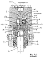
- reference numeral 1a denotes a connector on a Pump housing 1c of the fuel injection pump, being in the pump housing 1c Pump cylinder 1b is formed.
- a pump piston 2 in is in the pump cylinder 1b Slidably mounted in the axial direction, which one at the top of the pump cylinder 1b trained pressure space 3 limited.
- the end face of the pressure chamber 3 Pump piston 2 forms a piston head 5.
- the pump piston 2 has at its in the figures no longer shown lower end via a piston foot through which he by means of a cam driven by the internal combustion engine in an oscillating manner is driven.
- one is also in at the lower end of the pump piston 2 arranged in the figures not shown piston flag, by means of which Pump piston 2 for controlling the injection duration and quantity via a predetermined one Angular range is rotatable about its axis.
- the pump piston 2 On the piston head 5, the pump piston 2 has an upper pressure chamber side Control edge 6. Furthermore, there are two lower, sloping ends on the pump piston 2 Control edges 7 formed. The upper control edge 6 and the lower control edge 7 limit together with a connection of the pressure chamber 3 to the bottom of the oblique control edges 7 producing piston groove 8 each a control triangle, which by painting each one with a suction space 20 outside the Pump cylinder 1b connected, opening into the pressure chamber 3 Control bore 4a, 4b start and end of fuel delivery of the injection pump certainly.
- Piston flag By rotating the pump piston 2 by means of the aforementioned Piston flag is created by changing the mutual position of the lower control edge 7 and control bore 4a, 4b the end of fuel delivery and thus the injection duration set.
- the fuel injection pump described corresponds to the known.
- the fuel displaced from the pressure chamber 3 by the pump piston 2 is supplied via a a delivery valve 9 containing a pressure valve 21 and via a pressure connection 22 for Delivery to a fuel injector for injection into the combustion chamber Internal combustion engine delivered.
- connection piece 1 a the pump piston 2 is upstream of the pressure chamber Dodge piston 12 slidably disposed in a bore 10.
- the escape piston 12 delimits an escape space 18 on its underside, compare FIG a connecting channel 19 with the pressure chamber 3 of the fuel injection pump in Connection is established.
- the evasive piston 12 is in the sense of increasing the Alternative space 18 between an initial position and an end position over one Dodge stroke s displaceable, see Figure 1a).
- Control piston 11 slidably mounted. Between the escape piston 12 and the control piston 11, an auxiliary spring 13 is provided, which the escape piston 12 forces towards its initial position closer to the pressure chamber 3. Furthermore is a volume enclosed between the escape piston 12 and the control piston 11 Coupled with the suction chamber 20 via a connecting channel 14.
- the room above the Control piston 11 is connected to a hydraulic connection 16 via a hydraulic channel 17 connected, which with a control hydraulics not shown in the figure in Connection is established.
- a stop 15 is formed at the upper end of the bore 10, which serves to limit the displacement path of the control piston 12 upwards.
- the control piston 11 slidably mounted in the bore 10 forms a hydraulic one actuated adjusting device for adjusting the evasive stroke s of the evasive piston 12th
- a flat seat 12a is formed, which with one leading to the pressure chamber 3 Connection channel 19 surrounding sealing surface 12b cooperates. If the flat seat 12a rests on the sealing surface 12b, that of the one in the pressure chamber 3 is Fuel injection pump pressurized fuel Area of the evasive piston 12 smaller than the area of the control piston 11, which over the hydraulic channel 17 is pressurized by the control hydraulics. That is, it is a smaller pressure supplied via the hydraulic channel 17 sufficient to the Dodge piston 12 to hold the flat seat 12a on the sealing surface 12b as the pressure of the fuel in the pressure chamber 3. This allows, for example, the use of a Lubricating oil pressure of 300 bar for the hydraulic actuation of the control piston 11.
- the control piston 11 is thus by means of the pressure supplied via the hydraulic channel 17 between an initial position, which is given when the evasive piston 12 with its flat seat 12a abuts the sealing surface 12b and the control piston 12 in turn abuts on the evasive piston 12, and an end position that can be moved by the The control piston 11 bears against the stop 15.
- Figure 1a shows the fuel injection pump in a state in which the pump piston 2 is at its bottom dead center.
- the control piston 11 is not pressurized via the hydraulic channel 17, so that due to the spring force of the auxiliary spring 13 and the pressure of the suction chamber 20 applied via the connecting channel 14, the control piston 11 is located at the upper stop 15 and the evasive piston 12 with its flat seat 12a on it Sealing surface 12b is present.
- the suction chamber pressure P s typically takes a value of up to 15 bar before the start of each injection.
- the evasive piston 12 is prepared for an evasive movement by the evasive stroke s in the direction of the control piston 11.
- Figure 1c shows the state in which the control piston 11 and the evasive piston 12 are in their lower position for an earlier start of injection. Because of the over the hydraulic channel 17 on the control piston 11 applied hydraulic pressure, which is, for example, 300 bar, the evasive piston 12 because of the Size ratio between the area of the hydraulic pressure Control piston 11 and located within the flat seat 12a, via the Connection channel 19 of the fuel pressure prevailing in the pressure chamber 3 acted upon surface of the evasive piston 12 with its flat seat 12a reliably held on the sealing surface 12b and thus an evasive movement the same made impossible, although the fuel pressure in the pressure chamber 3 one reached much higher value.
- hydraulic pressure which is, for example, 300 bar
- Fuel injection pump according to the invention takes place by means of the control piston 11 Switching between two states, namely one in which the evasive piston 12 is released and thus a delay of the evasive movement Injection is started at a later time, and a state in which prevents an evasive movement of the evasive piston 12 and thus a Injection takes place at an earlier point in time without delay.
- Such means for creating the stop 15 of the control piston 11 or for direct Adjustment of the evasive stroke s of the evasive piston 12 can be achieved by means of a Servomotor rotatable threaded spindle can be formed, which then a variable Federal start adjustment is possible.
Landscapes
- Engineering & Computer Science (AREA)
- Chemical & Material Sciences (AREA)
- Combustion & Propulsion (AREA)
- Mechanical Engineering (AREA)
- General Engineering & Computer Science (AREA)
- Fuel-Injection Apparatus (AREA)
- High-Pressure Fuel Injection Pump Control (AREA)
Abstract
Description
- 1a
- Anschlußstück
- 1b
- Pumpenzylinder
- 1c
- Pumpengehäuse
- 2
- Pumpenkolben
- 3
- Druckraum
- 4a,b
- Steuerbohrungen
- 5
- Kolbenkopf
- 6
- obere Steuerkante
- 7
- untere Steuerkante
- 8
- Kolbennut
- 9
- Förderkanal
- 10
- Bohrung
- 11
- Steuerkolben
- 12
- Ausweichkolben
- 12a
- Flachsitz
- 12b
- Dichtfläche
- 13
- Hilfsfeder
- 14
- Verbindungskanal
- 15
- Anschlag
- 16
- Hydraulikanschluß
- 17
- Hydraulikkanal
- 18
- Ausweichraum
- 19
- Verbindungskanal
- 20
- Saugraum
- 21
- Druckventil
- 22
- Druckanschluß
Claims (16)
- Kraftstoffeinspritzpumpe für eine Brennkraftmaschine mit einem in einem Pumpenzylinder (1b) geführten Pumpenkolben (2) und einem von dem Pumpenkolben (2) begrenzten Druckraum (3), aus welchem der von dem Pumpenkolben (2) geförderte Kraftstoff über einen Förderkanal (9) zur Zuführung in den Brennraum der Brennkraftmaschine abgegeben wird, wobei der Pumpenkolben (2) eine obere, druckraumseitig gelegene Steuerkante (6) und mindestens eine untere Steuerkante (7) aufweist, welche durch Überstreichen von mindestens einer mit einem Saugraum (20) der Kraftstoffeinspritzpumpe in Verbindung stehenden, in den Druckraum (3) mündenden Steuerbohrung (4a, 4b) Beginn und Ende der Kraftstofförderung der Einspritzpumpe bestimmen, dadurch gekennzeichnet, daß zur Verstellung des Beginns der Kraftstoffeinspritzung ein in einer Bohrung (10) verschieblich angeordneter Ausweichkolben (12) vorgesehen ist, welcher einen mit dem Druckraum (3) in Verbindung stehenden Ausweichraum (18) begrenzt und im Sinne einer Vergrößerung des Ausweichraums (18) über einen Ausweichhub s zwischen einer Anfangslage und einer Endlage verschiebbar ist, und daß Mittel zur Verstellung des Ausweichhubs s des Ausweichkolbens (12) vorgesehen sind.
- Kraftstoffeinspritzpumpe nach Anspruch 1, dadurch gekennzeichnet, daß der Ausweichkolben (12) im Gehäuse der Kraftstoffeinspritzpumpe angeordnet ist und mit dem Druckraum (3) in Verbindung steht.
- Kraftstoffeinspritzpumpe nach Anspruch 2, dadurch gekennzeichnet, daß der Ausweichkolben (12) am druckraumseitigen Ende in einem den Pumpenkopf bildenden Anschlußstück (1a) angeordnet ist, und daß ein den von dem Ausweichkolben (12) begrenzten Ausweichraum (18) mit dem Druckraum (3) verbindender Verbindungskanal (19) an der Stirnseite des Druckraums (3) mündet.
- Kraftstoffeinspritzpumpe nach Anspruch 1, 2 oder 3, dadurch gekennzeichnet, daß der Ausweichkolben (12) durch eine Hilfsfeder (13) zur Rückführung in seine Anfangslage federbelastet ist.
- Kraftstoffeinspritzpumpe nach einem der Ansprüche 1 bis 4, dadurch gekennzeichnet, daß der Ausweichkolben (12) zum Zwecke der Rückführung in seine Anfangslage an seiner Rückseite über einen Verbindungskanal (14) mit dem Saugraum (20) der Kraftstoffpumpe gekoppelt ist.
- Kraftstoffeinspritzpumpe nach einem der Ansprüche 1 bis 5, dadurch gekennzeichnet, daß die Mittel zur Verstellung des Ausweichhubs s des Ausweichkolbens (12) durch eine hyraulisch betätigte Verstelleinrichtung gebildet sind.
- Kraftstoffeinspritzpumpe nach Anspruch 6, dadurch gekennzeichnet, daß die hydraulisch betätigte Verstelleinrichtung durch einen in einer Bohrung (10) verschiebbaren, von einem unter Druck stehenden Fluid beaufschlagbaren Steuerkolben (11) gebildet ist, dessen Lage die Größe des Ausweichhubs s des Ausweichkolbens (12) bestimmt.
- Kraftstoffeinspritzpumpe nach Anspruch 7, dadurch gekennzeichnet, daß der Steuerkolben (11) und der Ausweichkolben (12) in einer gemeinsamen Bohrung (10) verschieblich gelagert sind, wobei der Steuerkolben (11) eine den Ausweichhub s des Ausweichkolbens (12) begrenzende Anlagefläche aufweist.
- Kraftstoffeinspritzpumpe nach Anspruch 7 oder 8, dadurch gekennzeichnet, daß der Steuerkolben (11) eine größere von dem unter Druck stehenden Fluid beaufschlagbare Fläche als die von dem in dem Druckraum (3) der Kraftstoffeinspritzpumpe befindlichen, unter Druck stehenden Kraftstoff beaufschlagte Fläche des Ausweichkolbens (12) aufweist.
- Kraftstoffeinspritzpumpe nach Anspruch 9, dadurch gekennzeichnet, daß an dem Ausweichkolben (12) ein mit einer den zum Druckraum (3) führenden Verbindungskanal (19) umgebenden Dichtfläche (12b) zusammenwirkender Flachsitz (12a) ausgebildet ist, wobei die bei an der Dichtfläche (12b) anliegendem Flachsitz (12a) von dem im Druckraum (3) befindlichen unter Druck stehenden Kraftstoff beaufschlagte Fläche des Ausweichkolbens (12) kleiner als die von dem unter Druck stehenden Fluid beaufschlagte Fläche des Steuerkolbens (11) ist.
- Kraftstoffeinspritzpumpe nach einem der Ansprüche 7 bis 10, dadurch gekennzeichnet, daß der Steuerkolben (11) zur hydraulischen Betätigung durch den Schmieröldruck der Brennkraftmaschine beaufschlagbar ist.
- Kraftstoffeinspritzpumpe nach einem der Ansprüche 6 bis 11, dadurch gekennzeichnet, daß eine Steuereinrichtung zum Zu- und Abschalten des den Steuerkolben (11) betätigenden hydraulischen Drucks vorgesehen ist.
- Kraftstoffeinspritzpumpe nach einem der Ansprüche 7 bis 12, dadurch gekennzeichnet, daß der Steuerkolben (11) zwischen einer Anfangslage und einer durch einen Anschlag (15) begrenzten Endlage verschiebbar ist.
- Kraftstoffeinspritzpumpe nach Anspruch 13, dadurch gekennzeichnet, daß der in Endlage des Steuerkolbens (11) begrenzende Anschlag (15) verstellbar ist, und daß Mittel zur Verstellung des Anschlags (15) vorgesehen sind.
- Kraftstoffeinspritzpumpe nach Anspruch 14, dadurch gekennzeichnet, daß die Mittel zur Verstellung des Anschlags (15) durch eine mittels eines Stellmotors drehbare Gewindespindel gebildet sind.
- Kraftstoffeinspritzpumpe nach einem der Ansprüche 1 bis 5, dadurch gekennzeichnet, daß die Mittel zur Verstellung des Ausweichhubs s des Ausweichkolbens (12) durch eine mittels eines Stellmotors drehbare Gewindespindel gebildet sind, welche eine Verschiebung eines die Anfangs- oder Endlage des Ausweichkolbens (12) begrenzenden Anschlags bewirken.
Applications Claiming Priority (2)
| Application Number | Priority Date | Filing Date | Title |
|---|---|---|---|
| DE19831077 | 1998-07-10 | ||
| DE19831077A DE19831077A1 (de) | 1998-07-10 | 1998-07-10 | Kraftstoffeinspritzpumpe für eine Brennkraftmaschine |
Publications (3)
| Publication Number | Publication Date |
|---|---|
| EP0971122A2 true EP0971122A2 (de) | 2000-01-12 |
| EP0971122A3 EP0971122A3 (de) | 2001-04-18 |
| EP0971122B1 EP0971122B1 (de) | 2003-05-14 |
Family
ID=7873707
Family Applications (1)
| Application Number | Title | Priority Date | Filing Date |
|---|---|---|---|
| EP99113211A Expired - Lifetime EP0971122B1 (de) | 1998-07-10 | 1999-07-08 | Kraftstoffeinspritzpumpe für eine Brennkraftmaschine |
Country Status (3)
| Country | Link |
|---|---|
| EP (1) | EP0971122B1 (de) |
| AT (1) | ATE240456T1 (de) |
| DE (2) | DE19831077A1 (de) |
Cited By (2)
| Publication number | Priority date | Publication date | Assignee | Title |
|---|---|---|---|---|
| WO2007060285A1 (en) * | 2005-11-23 | 2007-05-31 | Wärtsilä Finland Oy | Injection pump for a piston engine |
| US20130156620A1 (en) * | 2010-10-20 | 2013-06-20 | Hyundai Heavy Industries, Co., Ltd. | Fuel injection pump including a variable pressure compartment |
Families Citing this family (3)
| Publication number | Priority date | Publication date | Assignee | Title |
|---|---|---|---|---|
| DE102004050021A1 (de) * | 2004-10-13 | 2006-04-20 | L'orange Gmbh | Magnetkolbenpumpe |
| KR101178630B1 (ko) | 2011-04-29 | 2012-08-30 | 현대중공업 주식회사 | 캠구동용 가변압력부를 구비한 연료분사펌프 |
| KR101219977B1 (ko) | 2011-04-29 | 2013-01-09 | 현대중공업 주식회사 | 유압 2단구동 가변압력실을 가진 연료분사펌프 |
Family Cites Families (7)
| Publication number | Priority date | Publication date | Assignee | Title |
|---|---|---|---|---|
| US2537087A (en) * | 1942-03-07 | 1951-01-09 | Atlas Diesel Ab | Fuel injection apparatus |
| US2810375A (en) * | 1953-04-13 | 1957-10-22 | Nordberg Manufacturing Co | Injection pump for internal combustion engines |
| CH328209A (de) * | 1953-12-23 | 1958-02-28 | Cav Ltd | Brennstoffeinspritzpumpe für Brennkraftmaschinen |
| US4469068A (en) * | 1981-11-10 | 1984-09-04 | Nippondenso Co., Ltd. | Fuel injection apparatus |
| JPS5977046A (ja) * | 1982-10-26 | 1984-05-02 | Nippon Denso Co Ltd | 燃料噴射装置 |
| JPS6062658A (ja) * | 1983-09-16 | 1985-04-10 | Mitsubishi Heavy Ind Ltd | ジャ−ク式燃料ポンプの噴射開始タイミング変更装置 |
| DE3801929C2 (de) * | 1987-01-30 | 1998-07-02 | Volkswagen Ag | Kraftstoffeinspritzeinrichtung |
-
1998
- 1998-07-10 DE DE19831077A patent/DE19831077A1/de not_active Withdrawn
-
1999
- 1999-07-08 EP EP99113211A patent/EP0971122B1/de not_active Expired - Lifetime
- 1999-07-08 AT AT99113211T patent/ATE240456T1/de active
- 1999-07-08 DE DE59905531T patent/DE59905531D1/de not_active Expired - Lifetime
Non-Patent Citations (1)
| Title |
|---|
| None |
Cited By (5)
| Publication number | Priority date | Publication date | Assignee | Title |
|---|---|---|---|---|
| WO2007060285A1 (en) * | 2005-11-23 | 2007-05-31 | Wärtsilä Finland Oy | Injection pump for a piston engine |
| JP2009516804A (ja) * | 2005-11-23 | 2009-04-23 | ワルトシラ フィンランド オサケユキチュア | 容積式機関用の噴射ポンプ |
| US7603987B2 (en) | 2005-11-23 | 2009-10-20 | Wartsila Finland Oy | Injection pump for a piston engine |
| US20130156620A1 (en) * | 2010-10-20 | 2013-06-20 | Hyundai Heavy Industries, Co., Ltd. | Fuel injection pump including a variable pressure compartment |
| US9051925B2 (en) * | 2010-10-20 | 2015-06-09 | Hyundai Heavy Industries Co., Ltd. | Fuel injection pump including a variable pressure compartment |
Also Published As
| Publication number | Publication date |
|---|---|
| DE19831077A1 (de) | 2000-01-13 |
| ATE240456T1 (de) | 2003-05-15 |
| EP0971122B1 (de) | 2003-05-14 |
| EP0971122A3 (de) | 2001-04-18 |
| DE59905531D1 (de) | 2003-06-18 |
Similar Documents
| Publication | Publication Date | Title |
|---|---|---|
| EP0141044B1 (de) | Kraftstoffeinspritzeinrichtung mit Vor- und Haupteinspritzung bei Brennkraftmaschinen | |
| DE3590194C2 (de) | Brennstoff-Einspritzpumpe | |
| EP0736672B1 (de) | Verfahren zur Motorbremsung mit einem 4-Takt-Verbrennungsmotor | |
| EP2333336B1 (de) | Kolbenmaschine zum Einsatz als Vakuumpumpe für medizinische Zwecke | |
| DE1947641C3 (de) | Als Pumpe oder Motor ausgebildete Maschine veränderlicher Verdrängung | |
| DE69013283T2 (de) | Hochdruck-Kraftstoffeinspritzeinheit mit Steuerung des Druckes der Kammer für den Spritzzeitpunkt. | |
| DE4221134C1 (de) | ||
| EP1654453A1 (de) | Injektor für kraftstoff-einspritzsysteme von brennkraftmaschinen, insbesondere von direkteinspritzenden dieselmotoren | |
| DE102016208209A1 (de) | Hydraulische Kompressionsverstellung | |
| EP0226070A2 (de) | Pumpenanordnung zur dosierten Abgabe von mindestens zwei Komponenten | |
| WO1994024419A1 (de) | Nockenwellenantrieb | |
| EP1828651B1 (de) | Druckbegrenzungsventil mit reduzierter differenzfläche | |
| EP0971122B1 (de) | Kraftstoffeinspritzpumpe für eine Brennkraftmaschine | |
| EP0975856B1 (de) | Hubventil mit einer hydraulischen steuervorrichtung | |
| DE3428176C2 (de) | Kraftstoffeinspritzpumpe für Brennkraftmaschinen | |
| WO1989010479A1 (fr) | Unite de cylindre et piston a haute pression | |
| EP0090296A1 (de) | Einspritzdüse mit einem Nadelkolben | |
| DE2855812C2 (de) | ||
| DE3731240C2 (de) | Einspritzvorrichtung | |
| WO2003016682A1 (de) | Verfahren zum betreiben einer elektrohydraulischen ventilsteuerung einer brennkraftmaschine, computerprogramm sowie steuer- und regelgerät zum betreiben einer brennkraftmaschine | |
| EP1070002B1 (de) | Inchbremseinrichtung | |
| EP1377745B1 (de) | Verfahren zum betreiben einer pumpe-düse-einheit sowie pumpe-düse-einheit | |
| DE10147299A1 (de) | Vorrichtung zur Steuerung eines Öffnungsquerschnitts in einem Verbrennungszylinder einer Brennkraftmaschine | |
| DE4311672A1 (de) | Kraftstoffeinspritzpumpe | |
| EP1451465B1 (de) | Pumpe-düse-einheit |
Legal Events
| Date | Code | Title | Description |
|---|---|---|---|
| PUAI | Public reference made under article 153(3) epc to a published international application that has entered the european phase |
Free format text: ORIGINAL CODE: 0009012 |
|
| AK | Designated contracting states |
Kind code of ref document: A2 Designated state(s): AT CH DE GB IT LI |
|
| AX | Request for extension of the european patent |
Free format text: AL;LT;LV;MK;RO;SI |
|
| PUAL | Search report despatched |
Free format text: ORIGINAL CODE: 0009013 |
|
| AK | Designated contracting states |
Kind code of ref document: A3 Designated state(s): AT BE CH CY DE DK ES FI FR GB GR IE IT LI LU MC NL PT SE |
|
| AX | Request for extension of the european patent |
Free format text: AL;LT;LV;MK;RO;SI |
|
| RIC1 | Information provided on ipc code assigned before grant |
Free format text: 7F 02M 59/20 A, 7F 02M 59/24 B, 7F 02M 59/26 B, 7F 02M 59/22 B |
|
| 17P | Request for examination filed |
Effective date: 20010517 |
|
| AKX | Designation fees paid |
Free format text: AT CH DE GB IT LI |
|
| 17Q | First examination report despatched |
Effective date: 20020201 |
|
| GRAH | Despatch of communication of intention to grant a patent |
Free format text: ORIGINAL CODE: EPIDOS IGRA |
|
| GRAH | Despatch of communication of intention to grant a patent |
Free format text: ORIGINAL CODE: EPIDOS IGRA |
|
| GRAA | (expected) grant |
Free format text: ORIGINAL CODE: 0009210 |
|
| AK | Designated contracting states |
Designated state(s): AT CH DE GB IT LI |
|
| REG | Reference to a national code |
Ref country code: GB Ref legal event code: FG4D Free format text: NOT ENGLISH |
|
| REG | Reference to a national code |
Ref country code: CH Ref legal event code: EP |
|
| REG | Reference to a national code |
Ref country code: CH Ref legal event code: NV Representative=s name: ISLER & PEDRAZZINI AG |
|
| REF | Corresponds to: |
Ref document number: 59905531 Country of ref document: DE Date of ref document: 20030618 Kind code of ref document: P |
|
| GBT | Gb: translation of ep patent filed (gb section 77(6)(a)/1977) | ||
| PLBE | No opposition filed within time limit |
Free format text: ORIGINAL CODE: 0009261 |
|
| STAA | Information on the status of an ep patent application or granted ep patent |
Free format text: STATUS: NO OPPOSITION FILED WITHIN TIME LIMIT |
|
| 26N | No opposition filed |
Effective date: 20040217 |
|
| REG | Reference to a national code |
Ref country code: CH Ref legal event code: PCAR Free format text: ISLER & PEDRAZZINI AG;POSTFACH 1772;8027 ZUERICH (CH) |
|
| PGFP | Annual fee paid to national office [announced via postgrant information from national office to epo] |
Ref country code: AT Payment date: 20130711 Year of fee payment: 15 Ref country code: CH Payment date: 20130719 Year of fee payment: 15 Ref country code: DE Payment date: 20130722 Year of fee payment: 15 |
|
| PGFP | Annual fee paid to national office [announced via postgrant information from national office to epo] |
Ref country code: GB Payment date: 20130719 Year of fee payment: 15 |
|
| PGFP | Annual fee paid to national office [announced via postgrant information from national office to epo] |
Ref country code: IT Payment date: 20130729 Year of fee payment: 15 |
|
| REG | Reference to a national code |
Ref country code: DE Ref legal event code: R119 Ref document number: 59905531 Country of ref document: DE |
|
| REG | Reference to a national code |
Ref country code: CH Ref legal event code: PL |
|
| REG | Reference to a national code |
Ref country code: AT Ref legal event code: MM01 Ref document number: 240456 Country of ref document: AT Kind code of ref document: T Effective date: 20140708 |
|
| GBPC | Gb: european patent ceased through non-payment of renewal fee |
Effective date: 20140708 |
|
| PG25 | Lapsed in a contracting state [announced via postgrant information from national office to epo] |
Ref country code: LI Free format text: LAPSE BECAUSE OF NON-PAYMENT OF DUE FEES Effective date: 20140731 Ref country code: DE Free format text: LAPSE BECAUSE OF NON-PAYMENT OF DUE FEES Effective date: 20150203 Ref country code: IT Free format text: LAPSE BECAUSE OF NON-PAYMENT OF DUE FEES Effective date: 20140708 Ref country code: CH Free format text: LAPSE BECAUSE OF NON-PAYMENT OF DUE FEES Effective date: 20140731 |
|
| REG | Reference to a national code |
Ref country code: DE Ref legal event code: R119 Ref document number: 59905531 Country of ref document: DE Effective date: 20150203 |
|
| PG25 | Lapsed in a contracting state [announced via postgrant information from national office to epo] |
Ref country code: AT Free format text: LAPSE BECAUSE OF NON-PAYMENT OF DUE FEES Effective date: 20140708 Ref country code: GB Free format text: LAPSE BECAUSE OF NON-PAYMENT OF DUE FEES Effective date: 20140708 |