EP0972983A2 - Abblendscheinwerfer mit einem reflektierenden Schwenksegment - Google Patents
Abblendscheinwerfer mit einem reflektierenden Schwenksegment Download PDFInfo
- Publication number
- EP0972983A2 EP0972983A2 EP99890217A EP99890217A EP0972983A2 EP 0972983 A2 EP0972983 A2 EP 0972983A2 EP 99890217 A EP99890217 A EP 99890217A EP 99890217 A EP99890217 A EP 99890217A EP 0972983 A2 EP0972983 A2 EP 0972983A2
- Authority
- EP
- European Patent Office
- Prior art keywords
- swivel
- segment
- low
- swivel segment
- reflector
- Prior art date
- Legal status (The legal status is an assumption and is not a legal conclusion. Google has not performed a legal analysis and makes no representation as to the accuracy of the status listed.)
- Granted
Links
- 238000007598 dipping method Methods 0.000 title 1
- 230000003287 optical effect Effects 0.000 claims description 7
- 238000005286 illumination Methods 0.000 abstract description 2
- 230000007704 transition Effects 0.000 description 4
- 238000010276 construction Methods 0.000 description 2
- 230000003760 hair shine Effects 0.000 description 2
- 229920001971 elastomer Polymers 0.000 description 1
- 239000000806 elastomer Substances 0.000 description 1
- 230000004907 flux Effects 0.000 description 1
- 239000000463 material Substances 0.000 description 1
- 230000005855 radiation Effects 0.000 description 1
- 238000007789 sealing Methods 0.000 description 1
Images

Classifications
-
- F—MECHANICAL ENGINEERING; LIGHTING; HEATING; WEAPONS; BLASTING
- F21—LIGHTING
- F21V—FUNCTIONAL FEATURES OR DETAILS OF LIGHTING DEVICES OR SYSTEMS THEREOF; STRUCTURAL COMBINATIONS OF LIGHTING DEVICES WITH OTHER ARTICLES, NOT OTHERWISE PROVIDED FOR
- F21V7/00—Reflectors for light sources
- F21V7/04—Optical design
- F21V7/09—Optical design with a combination of different curvatures
-
- F—MECHANICAL ENGINEERING; LIGHTING; HEATING; WEAPONS; BLASTING
- F21—LIGHTING
- F21S—NON-PORTABLE LIGHTING DEVICES; SYSTEMS THEREOF; VEHICLE LIGHTING DEVICES SPECIALLY ADAPTED FOR VEHICLE EXTERIORS
- F21S41/00—Illuminating devices specially adapted for vehicle exteriors, e.g. headlamps
- F21S41/30—Illuminating devices specially adapted for vehicle exteriors, e.g. headlamps characterised by reflectors
- F21S41/32—Optical layout thereof
- F21S41/33—Multi-surface reflectors, e.g. reflectors with facets or reflectors with portions of different curvature
- F21S41/331—Multi-surface reflectors, e.g. reflectors with facets or reflectors with portions of different curvature the reflector consisting of complete annular areas
-
- F—MECHANICAL ENGINEERING; LIGHTING; HEATING; WEAPONS; BLASTING
- F21—LIGHTING
- F21S—NON-PORTABLE LIGHTING DEVICES; SYSTEMS THEREOF; VEHICLE LIGHTING DEVICES SPECIALLY ADAPTED FOR VEHICLE EXTERIORS
- F21S41/00—Illuminating devices specially adapted for vehicle exteriors, e.g. headlamps
- F21S41/60—Illuminating devices specially adapted for vehicle exteriors, e.g. headlamps characterised by a variable light distribution
- F21S41/67—Illuminating devices specially adapted for vehicle exteriors, e.g. headlamps characterised by a variable light distribution by acting on reflectors
- F21S41/675—Illuminating devices specially adapted for vehicle exteriors, e.g. headlamps characterised by a variable light distribution by acting on reflectors by moving reflectors
Definitions
- the invention relates to a low beam headlight with a reflective Swivel segment in the area of the reflector edge.
- a foldable reflector section is now proposed not to fold out of the beam path, but into the beam path in order to To converge light towards the optical axis and thus the inner curve apron to illuminate.
- headlights it was known headlights as a whole depending on the steering control.
- Another object of the invention is to increase the luminous efficiency of the swivel segment.
- the invention provides that in general parabolic reflector is provided at least one zone in horizontal section at least approximately forms part of an ellipse, in one focus there is a light source and its other focus on the surface of the um there is a vertical axis of pivotable swivel segment.
- the height of the zone preferably corresponds to an elliptical horizontal section about the height of the swivel segment.
- the swivel segment is a component separate from the reflector is.
- the ellipse region is matched to the swivel segment so that in the zero swivel position edge ray of the ellipse region near the swivel segment parallel to the optical axis and in the maximum swivel position of the edge beam remote from the swivel segment Ellipse area at right angles to the optical axis.
- the pivot segment can be planar or have a curved surface as well also have scattering elements, such as in particular vertical grooves.
- the control of the swivel segment is not restricted and can e.g. mechanically, hydraulically or preferably electronically via sensors and Processors are carried out that primarily record the radius of the curve.
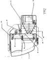
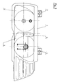
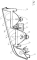
- Fig. 1 is a horizontal section in the Lamp level through a light collector reflector / swivel segment combination is as well 2 to 4 show their practical implementation, with Fig. 2 an enlarged Is a cross-sectional view showing an automatic headlight range adjustment, Fig. 3 is a front view and Fig. 4 is a horizontal section of the corresponding Combination headlight insert is.
- a horizontal area AB of a generally in Horizontal section of the parabolic reflector is designed as a section of an ellipse, in whose one focus is the associated lamp L and in its other focus a reflective swivel segment 14 which can be swiveled about a vertical axis 12 is arranged.
- the reflector has two floors, so to speak, and steps and Transitions from the parabolic area to the ellipse area.
- the marginal rays relating to the starting point A and the ending point B of the Ellipse range are with respect to a zero position and a maximum deflection position of the Swivel segment 14 shown.
- end point B becomes parallel mapped to the optical axis OA, the light beam a shines more in the direction of travel.
- the starting point A is at a right angle to Optical axis OA shown, the light beam a shines more to the side.
- Swiveling the swivel segment 14 is thus in the illustrated embodiment an area of 90 ° can be illuminated.
- the swivel angle of the Swivel segment 14 can be selected as required.
- the floor with an elliptical horizontal section thus targets the swivel segment 14, the parabolic area gives the basic light distribution and the transition zones, which in the Horizontal section of Fig. 1, the curve sections AC and BD result, serve the closed appearance of the reflector for the viewer.
- the amount of Area with an elliptical horizontal section can be selected so that the Parabolic surface makes up about 2/3 of the reflector surface, as well as the elliptical area plus the rest of the transition zones. This would be one for an H7 lamp Luminous flux distribution parabolic area: ellipse area: transition area of 400: 150 : 50 result.
- a frame 1 provided with retaining tabs 2 carries a cover plate 3 and has a rear wall 4 in the turn signal area, in which the socket for the Flashing light sits freely accessible. Furthermore, the frame 1 has two windows 5, behind which a double headlight unit 6 is arranged, opposite one Support bracket 7 of the frame 1 is pivotable.
- the support bracket 7 has one Ball head bearing 8, around which the double headlight unit 6 can be pivoted, for which purpose a sliding pin drive 9 is mounted on the support bracket 7, which has a Ball head connection 10 attacks on the double headlight unit 6. In this way automated headlight range adjustment can be carried out in the usual way.
- the third pivot point is arranged on the side of the double headlight unit 6 and not shown).
- the double headlight unit 6 is provided with a sealing bellows 11 made of elastomer material connected to the frame 1 and has no rear cover, so the sockets are directly accessible for the respective lamps. This offers compared to previous ones Constructions a much reduced space requirement and greatly improved Ease of use and greatly improved heat radiation options.
- the Low beam headlight reflector 13 is fixed to the Double headlight unit 6 connected to a drive motor 15, which is provided via a pinion operation 16 in the additional reflector segment 14 about an axis 12 in the Beam path of the low beam reflector 13 can pivot into the Illumination of the apron inside the curve serves.
Landscapes
- Engineering & Computer Science (AREA)
- General Engineering & Computer Science (AREA)
- Lighting Device Outwards From Vehicle And Optical Signal (AREA)
- Non-Portable Lighting Devices Or Systems Thereof (AREA)
- Aerials With Secondary Devices (AREA)
- Golf Clubs (AREA)
- Road Signs Or Road Markings (AREA)
Abstract
Description
Claims (6)
- Abblendlichtscheinwerfer mit einem reflektierenden Schwenksegment im Bereich des Reflektorrands, dadurch gekennzeichnet, daß das Schwenksegment kurvenradiusabhängig in den Strahlengang des Scheinwerfers hineinschwenkbar vorgesehen ist.
- Abblendscheinwerfer nach Anspruch 1, dadurch gekennzeichnet, daß an einem allgemein parabolischen Reflektor zumindest eine Zone vorgesehen ist, die im Horizontalschnitt zumindest annäherungsweise einen Teil einer Ellipse bildet, in deren einem Brennpunkt sich eine Lichtquelle befindet und deren anderer Brennpunkt auf der Oberfläche des um eine vertikale Achse schwenkbaren Schwenksegments liegt.
- Abblendscheinwerfer nach Anspruch 1 oder 2, dadurch gekennzeichnet, daß die Höhe der Zone mit elliptischen Horizontalschnitt etwa der Höhe des Schwenksegments entspricht.
- Abblendscheinwerfer nach einem der Ansprüche 1 bis 3, dadurch gekennzeichnet, daß das Schwenksegment ein vom Reflektor getrennter Bauteil ist.
- Abblendscheinwerfer nach einem der Ansprüche 1 bis 4, dadurch gekennzeichnet, daß der Ellipsenbereich so auf das Schwenksegment abgestimmt ist, daß in der Nullschwenkstellung der schwenksegmentnahe Randstrahl des Ellipsenbereichs parallel zur optischen Achse und in der Maximalschwenkstellung der schwenksegmentferne Randstrahl des Ellipsenbereichs im rechten Winkel zur optischen Achse verläuft.
- Abblendscheinwerfer nach einem der Ansprüche 1 bis 5, dadurch gekennzeichnet, daß das Schwenksegment Streuelemente aufweist, insbesondere in Form von Vertikalriefen.
Priority Applications (1)
| Application Number | Priority Date | Filing Date | Title |
|---|---|---|---|
| AT99890217T ATE321975T1 (de) | 1998-07-17 | 1999-07-01 | Abblendscheinwerfer mit einem reflektierenden schwenksegment |
Applications Claiming Priority (2)
| Application Number | Priority Date | Filing Date | Title |
|---|---|---|---|
| AT0123998A AT500425B8 (de) | 1998-07-17 | 1998-07-17 | Abblendscheinwerfer mit einem reflektierenden schwenksegment |
| AT123998 | 1998-07-17 |
Publications (3)
| Publication Number | Publication Date |
|---|---|
| EP0972983A2 true EP0972983A2 (de) | 2000-01-19 |
| EP0972983A3 EP0972983A3 (de) | 2001-07-04 |
| EP0972983B1 EP0972983B1 (de) | 2006-03-29 |
Family
ID=3509622
Family Applications (1)
| Application Number | Title | Priority Date | Filing Date |
|---|---|---|---|
| EP99890217A Expired - Lifetime EP0972983B1 (de) | 1998-07-17 | 1999-07-01 | Abblendscheinwerfer mit einem reflektierenden Schwenksegment |
Country Status (4)
| Country | Link |
|---|---|
| EP (1) | EP0972983B1 (de) |
| AT (2) | AT500425B8 (de) |
| DE (1) | DE59913281D1 (de) |
| ES (1) | ES2262304T3 (de) |
Cited By (2)
| Publication number | Priority date | Publication date | Assignee | Title |
|---|---|---|---|---|
| EP1152188A3 (de) * | 2000-04-05 | 2004-01-02 | Philips Intellectual Property & Standards GmbH | Beleuchtungseinrichtung und Verfahren zum Betreiben einer Beleuchtungseinrichtung |
| AT500562A1 (de) * | 2003-10-28 | 2006-01-15 | Zizala Lichtsysteme Gmbh | Fahrzeugscheinwerfer |
Citations (1)
| Publication number | Priority date | Publication date | Assignee | Title |
|---|---|---|---|---|
| DE4419365A1 (de) | 1994-06-03 | 1995-12-07 | Bosch Gmbh Robert | Scheinwerfer für Fahrzeuge |
Family Cites Families (9)
| Publication number | Priority date | Publication date | Assignee | Title |
|---|---|---|---|---|
| FR1520656A (fr) * | 1967-02-28 | 1968-04-12 | Cibie Projecteurs | Projecteur perfectionné à déviation de faisceau |
| DE2523643C3 (de) * | 1975-05-28 | 1978-09-21 | Hans-Joachim 4010 Hilden Schurig | Reflektor mit einstellbarem Abstrahlwinkel |
| JPH0636321B2 (ja) * | 1988-02-02 | 1994-05-11 | 株式会社小糸製作所 | 自動車用灯具 |
| US5023758A (en) * | 1989-11-13 | 1991-06-11 | General Electric Company | Single arc discharge headlamp with light switch for high/low beam operation |
| JPH076564Y2 (ja) * | 1990-04-19 | 1995-02-15 | 株式会社小糸製作所 | 配光可変型自動車用前照灯 |
| DE4418733A1 (de) * | 1994-05-28 | 1995-11-30 | Bosch Gmbh Robert | Scheinwerfer für Fahrzeuge für Fern- und Abblendlicht |
| FR2727497A1 (fr) * | 1994-11-30 | 1996-05-31 | Valeo Vision | Projecteur a elargissement de faisceau, notamment pour vehicule automobile |
| DE19634755B4 (de) * | 1996-08-28 | 2008-01-31 | Automotive Lighting Reutlingen Gmbh | Beleuchtungseinrichtung eines Fahrzeugs |
| FR2759651B1 (fr) * | 1997-02-18 | 1999-03-19 | Renault | Projecteur de vehicule automobile comportant un reflecteur fractionne en lames orientables |
-
1998
- 1998-07-17 AT AT0123998A patent/AT500425B8/de not_active IP Right Cessation
-
1999
- 1999-07-01 AT AT99890217T patent/ATE321975T1/de not_active IP Right Cessation
- 1999-07-01 EP EP99890217A patent/EP0972983B1/de not_active Expired - Lifetime
- 1999-07-01 DE DE59913281T patent/DE59913281D1/de not_active Expired - Lifetime
- 1999-07-01 ES ES99890217T patent/ES2262304T3/es not_active Expired - Lifetime
Patent Citations (1)
| Publication number | Priority date | Publication date | Assignee | Title |
|---|---|---|---|---|
| DE4419365A1 (de) | 1994-06-03 | 1995-12-07 | Bosch Gmbh Robert | Scheinwerfer für Fahrzeuge |
Cited By (3)
| Publication number | Priority date | Publication date | Assignee | Title |
|---|---|---|---|---|
| EP1152188A3 (de) * | 2000-04-05 | 2004-01-02 | Philips Intellectual Property & Standards GmbH | Beleuchtungseinrichtung und Verfahren zum Betreiben einer Beleuchtungseinrichtung |
| AT500562A1 (de) * | 2003-10-28 | 2006-01-15 | Zizala Lichtsysteme Gmbh | Fahrzeugscheinwerfer |
| AT500562B1 (de) * | 2003-10-28 | 2007-10-15 | Zizala Lichtsysteme Gmbh | Fahrzeugscheinwerfer |
Also Published As
| Publication number | Publication date |
|---|---|
| EP0972983B1 (de) | 2006-03-29 |
| AT500425B8 (de) | 2007-02-15 |
| ATE321975T1 (de) | 2006-04-15 |
| AT500425A1 (de) | 2005-12-15 |
| EP0972983A3 (de) | 2001-07-04 |
| AT500425B1 (de) | 2006-04-15 |
| DE59913281D1 (de) | 2006-05-18 |
| ES2262304T3 (es) | 2006-11-16 |
Similar Documents
| Publication | Publication Date | Title |
|---|---|---|
| DE69829895T2 (de) | Scheinwerfer | |
| DE19508472C2 (de) | Fahrzeugscheinwerfer mit einer Anzahl von Leuchten | |
| DE102004034838B4 (de) | Fahrzeugscheinwerfersystem mit variabler Strahlform | |
| DE10262294B4 (de) | Scheinwerfer | |
| EP0225313B1 (de) | Fahrzeugleuchte | |
| DE4418135B4 (de) | Kraftfahrzeugscheinwerfer mit veränderbarer Lichtverteilung | |
| DE10100176B4 (de) | Leuchte mit einer Reflektoranordnung mit mehreren Reflexionsflächen, insbesondere für ein Kraftfahrzeug | |
| DE10108777B4 (de) | Fahrzeugscheinwerfervorrichtung mit Waschfunktion | |
| AT514161B1 (de) | Leuchteinheit mit Blende mit zumindest einem Lichtfenster | |
| EP1914118A2 (de) | Aussenrückspiegel mit Leuchtmittel | |
| DE60120263T2 (de) | Fahrzeugscheinwerfer mit einem rohrähnlichen Lampenelement | |
| EP1923266B1 (de) | Aussenrückblickspiegel für Fahrzeuge | |
| DE2726951C2 (de) | Scheinwerfer für Kraftfahrzeuge | |
| DE102007021773B4 (de) | Projektortyp-Frontscheinwerfer-Baugruppe mit verringerter Baulänge | |
| DE3336306A1 (de) | Abgeflachter scheinwerfer fuer motorfahrzeuge | |
| DE202010002800U1 (de) | Beleuchtungseinrichtung für ein Kraftfahrzeug | |
| DE19846797A1 (de) | Scheinwerfer in elliptischer Ausführung mit vergrößertem Leuchtfeld | |
| DE102007038563A1 (de) | Beleuchtungssystem für ein Kraftfahrzeug | |
| DE2056996B2 (de) | Beleuchtungseinrichtung fuer kraftfahrzeuge | |
| EP1070911A2 (de) | Scheinwerfer für Kraftfahrzeuge | |
| EP0972983B1 (de) | Abblendscheinwerfer mit einem reflektierenden Schwenksegment | |
| DE3527877C2 (de) | Fahrzeugscheinwerfer mit mehreren getrennten Reflektoren | |
| EP0974786B1 (de) | Scheinwerferanordnung nach dem Projektionstyp für ein Kraftfahrzeug | |
| DE19851044A1 (de) | Fahrzeugscheinwerfer mit verbesserter Beleuchtungsdichte aus der Lichtenergie für das Fernlicht | |
| DE10012634A1 (de) | Kraftfahrzeugscheinwerfer mit aktivem Rückwandbereich |
Legal Events
| Date | Code | Title | Description |
|---|---|---|---|
| PUAI | Public reference made under article 153(3) epc to a published international application that has entered the european phase |
Free format text: ORIGINAL CODE: 0009012 |
|
| AK | Designated contracting states |
Kind code of ref document: A2 Designated state(s): AT BE CH CY DE DK ES FI FR GB GR IE IT LI LU MC NL PT SE |
|
| AX | Request for extension of the european patent |
Free format text: AL;LT;LV;MK;RO;SI |
|
| PUAL | Search report despatched |
Free format text: ORIGINAL CODE: 0009013 |
|
| AK | Designated contracting states |
Kind code of ref document: A3 Designated state(s): AT BE CH CY DE DK ES FI FR GB GR IE IT LI LU MC NL PT SE |
|
| AX | Request for extension of the european patent |
Free format text: AL;LT;LV;MK;RO;SI |
|
| 17P | Request for examination filed |
Effective date: 20011213 |
|
| AKX | Designation fees paid |
Free format text: AT BE CH CY DE DK ES FI FR GB GR IE IT LI LU MC NL PT SE |
|
| GRAP | Despatch of communication of intention to grant a patent |
Free format text: ORIGINAL CODE: EPIDOSNIGR1 |
|
| GRAS | Grant fee paid |
Free format text: ORIGINAL CODE: EPIDOSNIGR3 |
|
| GRAA | (expected) grant |
Free format text: ORIGINAL CODE: 0009210 |
|
| AK | Designated contracting states |
Kind code of ref document: B1 Designated state(s): AT BE CH CY DE DK ES FI FR GB GR IE IT LI LU MC NL PT SE |
|
| PG25 | Lapsed in a contracting state [announced via postgrant information from national office to epo] |
Ref country code: NL Free format text: LAPSE BECAUSE OF FAILURE TO SUBMIT A TRANSLATION OF THE DESCRIPTION OR TO PAY THE FEE WITHIN THE PRESCRIBED TIME-LIMIT Effective date: 20060329 Ref country code: IT Free format text: LAPSE BECAUSE OF FAILURE TO SUBMIT A TRANSLATION OF THE DESCRIPTION OR TO PAY THE FEE WITHIN THE PRESCRIBED TIME-LIMIT;WARNING: LAPSES OF ITALIAN PATENTS WITH EFFECTIVE DATE BEFORE 2007 MAY HAVE OCCURRED AT ANY TIME BEFORE 2007. THE CORRECT EFFECTIVE DATE MAY BE DIFFERENT FROM THE ONE RECORDED. Effective date: 20060329 Ref country code: IE Free format text: LAPSE BECAUSE OF FAILURE TO SUBMIT A TRANSLATION OF THE DESCRIPTION OR TO PAY THE FEE WITHIN THE PRESCRIBED TIME-LIMIT Effective date: 20060329 |
|
| REG | Reference to a national code |
Ref country code: GB Ref legal event code: FG4D Free format text: NOT ENGLISH |
|
| REG | Reference to a national code |
Ref country code: CH Ref legal event code: EP |
|
| REG | Reference to a national code |
Ref country code: IE Ref legal event code: FG4D Free format text: LANGUAGE OF EP DOCUMENT: GERMAN |
|
| REF | Corresponds to: |
Ref document number: 59913281 Country of ref document: DE Date of ref document: 20060518 Kind code of ref document: P |
|
| GBT | Gb: translation of ep patent filed (gb section 77(6)(a)/1977) |
Effective date: 20060523 |
|
| REG | Reference to a national code |
Ref country code: SE Ref legal event code: TRGR |
|
| PG25 | Lapsed in a contracting state [announced via postgrant information from national office to epo] |
Ref country code: DK Free format text: LAPSE BECAUSE OF FAILURE TO SUBMIT A TRANSLATION OF THE DESCRIPTION OR TO PAY THE FEE WITHIN THE PRESCRIBED TIME-LIMIT Effective date: 20060629 |
|
| PG25 | Lapsed in a contracting state [announced via postgrant information from national office to epo] |
Ref country code: MC Free format text: LAPSE BECAUSE OF NON-PAYMENT OF DUE FEES Effective date: 20060731 Ref country code: LI Free format text: LAPSE BECAUSE OF NON-PAYMENT OF DUE FEES Effective date: 20060731 Ref country code: CH Free format text: LAPSE BECAUSE OF NON-PAYMENT OF DUE FEES Effective date: 20060731 Ref country code: BE Free format text: LAPSE BECAUSE OF NON-PAYMENT OF DUE FEES Effective date: 20060731 |
|
| PG25 | Lapsed in a contracting state [announced via postgrant information from national office to epo] |
Ref country code: PT Free format text: LAPSE BECAUSE OF FAILURE TO SUBMIT A TRANSLATION OF THE DESCRIPTION OR TO PAY THE FEE WITHIN THE PRESCRIBED TIME-LIMIT Effective date: 20060829 |
|
| NLV1 | Nl: lapsed or annulled due to failure to fulfill the requirements of art. 29p and 29m of the patents act | ||
| REG | Reference to a national code |
Ref country code: IE Ref legal event code: FD4D |
|
| REG | Reference to a national code |
Ref country code: ES Ref legal event code: FG2A Ref document number: 2262304 Country of ref document: ES Kind code of ref document: T3 |
|
| ET | Fr: translation filed | ||
| REG | Reference to a national code |
Ref country code: CH Ref legal event code: PL |
|
| PLBE | No opposition filed within time limit |
Free format text: ORIGINAL CODE: 0009261 |
|
| STAA | Information on the status of an ep patent application or granted ep patent |
Free format text: STATUS: NO OPPOSITION FILED WITHIN TIME LIMIT |
|
| 26N | No opposition filed |
Effective date: 20070102 |
|
| PGFP | Annual fee paid to national office [announced via postgrant information from national office to epo] |
Ref country code: ES Payment date: 20070703 Year of fee payment: 9 |
|
| PG25 | Lapsed in a contracting state [announced via postgrant information from national office to epo] |
Ref country code: AT Free format text: LAPSE BECAUSE OF NON-PAYMENT OF DUE FEES Effective date: 20060701 |
|
| BERE | Be: lapsed |
Owner name: ZIZALA LICHTSYSTEME GMBH Effective date: 20060731 |
|
| PGFP | Annual fee paid to national office [announced via postgrant information from national office to epo] |
Ref country code: GB Payment date: 20070720 Year of fee payment: 9 |
|
| PG25 | Lapsed in a contracting state [announced via postgrant information from national office to epo] |
Ref country code: GR Free format text: LAPSE BECAUSE OF FAILURE TO SUBMIT A TRANSLATION OF THE DESCRIPTION OR TO PAY THE FEE WITHIN THE PRESCRIBED TIME-LIMIT Effective date: 20060630 |
|
| PG25 | Lapsed in a contracting state [announced via postgrant information from national office to epo] |
Ref country code: FI Free format text: LAPSE BECAUSE OF FAILURE TO SUBMIT A TRANSLATION OF THE DESCRIPTION OR TO PAY THE FEE WITHIN THE PRESCRIBED TIME-LIMIT Effective date: 20060329 |
|
| PG25 | Lapsed in a contracting state [announced via postgrant information from national office to epo] |
Ref country code: LU Free format text: LAPSE BECAUSE OF NON-PAYMENT OF DUE FEES Effective date: 20060701 |
|
| PG25 | Lapsed in a contracting state [announced via postgrant information from national office to epo] |
Ref country code: CY Free format text: LAPSE BECAUSE OF FAILURE TO SUBMIT A TRANSLATION OF THE DESCRIPTION OR TO PAY THE FEE WITHIN THE PRESCRIBED TIME-LIMIT Effective date: 20060329 |
|
| PGFP | Annual fee paid to national office [announced via postgrant information from national office to epo] |
Ref country code: FR Payment date: 20080627 Year of fee payment: 10 |
|
| EUG | Se: european patent has lapsed | ||
| GBPC | Gb: european patent ceased through non-payment of renewal fee |
Effective date: 20080701 |
|
| PG25 | Lapsed in a contracting state [announced via postgrant information from national office to epo] |
Ref country code: GB Free format text: LAPSE BECAUSE OF NON-PAYMENT OF DUE FEES Effective date: 20080701 |
|
| PGFP | Annual fee paid to national office [announced via postgrant information from national office to epo] |
Ref country code: SE Payment date: 20070731 Year of fee payment: 9 |
|
| REG | Reference to a national code |
Ref country code: ES Ref legal event code: FD2A Effective date: 20080702 |
|
| PG25 | Lapsed in a contracting state [announced via postgrant information from national office to epo] |
Ref country code: ES Free format text: LAPSE BECAUSE OF NON-PAYMENT OF DUE FEES Effective date: 20080702 |
|
| REG | Reference to a national code |
Ref country code: FR Ref legal event code: ST Effective date: 20100331 |
|
| PG25 | Lapsed in a contracting state [announced via postgrant information from national office to epo] |
Ref country code: FR Free format text: LAPSE BECAUSE OF NON-PAYMENT OF DUE FEES Effective date: 20090731 |
|
| PG25 | Lapsed in a contracting state [announced via postgrant information from national office to epo] |
Ref country code: SE Free format text: LAPSE BECAUSE OF NON-PAYMENT OF DUE FEES Effective date: 20080702 |
|
| PGFP | Annual fee paid to national office [announced via postgrant information from national office to epo] |
Ref country code: DE Payment date: 20110615 Year of fee payment: 13 |
|
| PG25 | Lapsed in a contracting state [announced via postgrant information from national office to epo] |
Ref country code: DE Free format text: LAPSE BECAUSE OF NON-PAYMENT OF DUE FEES Effective date: 20130201 |
|
| REG | Reference to a national code |
Ref country code: DE Ref legal event code: R119 Ref document number: 59913281 Country of ref document: DE Effective date: 20130201 |