EP0972984A2 - Fahrzeugscheinwerfer - Google Patents
Fahrzeugscheinwerfer Download PDFInfo
- Publication number
- EP0972984A2 EP0972984A2 EP99112685A EP99112685A EP0972984A2 EP 0972984 A2 EP0972984 A2 EP 0972984A2 EP 99112685 A EP99112685 A EP 99112685A EP 99112685 A EP99112685 A EP 99112685A EP 0972984 A2 EP0972984 A2 EP 0972984A2
- Authority
- EP
- European Patent Office
- Prior art keywords
- radiation
- vehicle headlight
- spring
- headlight according
- arms
- Prior art date
- Legal status (The legal status is an assumption and is not a legal conclusion. Google has not performed a legal analysis and makes no representation as to the accuracy of the status listed.)
- Ceased
Links
- 230000005855 radiation Effects 0.000 claims abstract description 50
- 238000005452 bending Methods 0.000 claims description 8
- 230000002093 peripheral effect Effects 0.000 claims description 5
- 229910052782 aluminium Inorganic materials 0.000 claims description 4
- XAGFODPZIPBFFR-UHFFFAOYSA-N aluminium Chemical group [Al] XAGFODPZIPBFFR-UHFFFAOYSA-N 0.000 claims description 4
- 230000015572 biosynthetic process Effects 0.000 claims description 2
- 230000036316 preload Effects 0.000 claims 1
- 238000011144 upstream manufacturing Methods 0.000 claims 1
- 230000003287 optical effect Effects 0.000 description 4
- 230000000694 effects Effects 0.000 description 1
- 238000009434 installation Methods 0.000 description 1
- 239000000463 material Substances 0.000 description 1
- 239000007769 metal material Substances 0.000 description 1
- 238000000034 method Methods 0.000 description 1
- 210000001331 nose Anatomy 0.000 description 1
- 239000002985 plastic film Substances 0.000 description 1
- 229920006255 plastic film Polymers 0.000 description 1
- 238000004080 punching Methods 0.000 description 1
Images
Classifications
-
- F—MECHANICAL ENGINEERING; LIGHTING; HEATING; WEAPONS; BLASTING
- F21—LIGHTING
- F21S—NON-PORTABLE LIGHTING DEVICES; SYSTEMS THEREOF; VEHICLE LIGHTING DEVICES SPECIALLY ADAPTED FOR VEHICLE EXTERIORS
- F21S41/00—Illuminating devices specially adapted for vehicle exteriors, e.g. headlamps
- F21S41/40—Illuminating devices specially adapted for vehicle exteriors, e.g. headlamps characterised by screens, non-reflecting members, light-shielding members or fixed shades
- F21S41/43—Illuminating devices specially adapted for vehicle exteriors, e.g. headlamps characterised by screens, non-reflecting members, light-shielding members or fixed shades characterised by the shape thereof
-
- F—MECHANICAL ENGINEERING; LIGHTING; HEATING; WEAPONS; BLASTING
- F21—LIGHTING
- F21S—NON-PORTABLE LIGHTING DEVICES; SYSTEMS THEREOF; VEHICLE LIGHTING DEVICES SPECIALLY ADAPTED FOR VEHICLE EXTERIORS
- F21S41/00—Illuminating devices specially adapted for vehicle exteriors, e.g. headlamps
- F21S41/40—Illuminating devices specially adapted for vehicle exteriors, e.g. headlamps characterised by screens, non-reflecting members, light-shielding members or fixed shades
- F21S41/47—Attachment thereof
Definitions
- the invention relates to a vehicle headlight with a reflector, the in Radiation direction is a radiation shield shielding a lamp, wherein the radiation diaphragm has at least two support arms for connecting the Radiation diaphragm with the edge area of a reflector opening.
- DE 36 24 131 A1 describes a vehicle headlight with a radiation diaphragm known, which is inserted from behind through the receptacle of the reflector and is attached to a rear reflector neck of the reflector.
- the Radiation diaphragm has two support arms oriented opposite to the direction of radiation on the free ends of which a flange is arranged.
- the flange has a bore within which there is a bore Screw extends into the inside of a threaded hole of the adjacent Reflector neck '.
- a positioning pin is also provided on the reflector neck for correct positioning of the flange.
- a disadvantage of the known Vehicle headlights is the complex assembly of the radiation shield on the Reflector neck.
- EP 0 718 545 A1 describes a vehicle headlight with a radiation diaphragm known, on the one hand, from an elongated cylindrical diaphragm part and on the other hand, there is a part shielding the directly emitted light.
- a disadvantage of the known vehicle headlights, which is due to the two-part design of the radiation diaphragm increased assembly effort necessary is.
- DE 41 26 044 C3 describes a vehicle headlight with a radiation diaphragm known, which is made from a single stamped part.
- the radiation shield has two opposite ones oriented opposite to the radiation direction Support arms, the free ends of which each have a U-shaped end section have that in at the front and back of a reflector neck engage arranged recesses. By bending the free end of the end portion about a transverse wedge-shaped The neck of the reflector is attached to the radiation shield on the back of the Reflector neck firmly connected to this.
- a disadvantage of the known Vehicle headlights is that the assembly of the radiation shield relatively expensive is.
- the object of the present invention is therefore the known Improve vehicle headlights so that the assembly of the radiation shield on the reflector is simplified.
- the diaphragm is a Retaining spring is associated with and under tension in the transverse direction spring arms extending in the longitudinal direction.
- the advantage of the invention is in particular that by the retaining spring a clamping or latching connection of the support arms with the reflector neck is made possible.
- To mount the radiation shield it is only necessary to Push the support arms inwards so far that the ends of the support arms into the engage through the opening formed by the reflector neck and join an inner Edge of the reflector neck.
- the snap lock thus formed enables quick and easy attachment and removal of the Radiation shield on the reflector neck.
- the Spring arms of the retaining spring on an inside of the support arms and thus cause radially outward clamping forces that the support arms on the Hold the reflector neck.
- the Radiation aperture on a dome and is made in one piece from a shiny Made of aluminum sheet, so that it is reliably prevented Incandescent lamp is visible from the outside through the clear cover plate. Also results an aesthetically pleasing impression.
- a Stiffening section of the retaining spring at right angles to the spring arms and runs in the transverse direction to the radiation diaphragm, with a central section being spaced apart and extends parallel to a plane formed by the spring arms.
- the support arms are hook-shaped Ends, on the inside facing the middle section the free end of the spring arm presses. This creates a targeted pressure point on the Exercised inside of the hook-shaped end, so that the support arms engage can intervene the reflector approach.
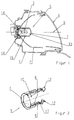
- a vehicle headlight consists essentially of a housing part (1) for Inclusion of a reflector (2) with an incandescent lamp (3) and a cover plate (4).
- the reflector (2) is assigned a radiation diaphragm (5) which is used for Shielding part of the light emitted by the incandescent lamp (3) is used.
- the radiation diaphragm (5) is essentially coaxial with an optical axis (6) of the reflector (2) arranged.
- the radiation shield (5) faces the cover plate (4) towards a dome (7) arranged transversely to the optical axis (6).
- the dome (7) is connected to the reflector (2) by two opposite support arms (8) connected.
- the radiation diaphragm (5) is made in one piece Stamped part (9) manufactured.
- the stamped part (9) is made of a sheet metal material, especially made of a high-gloss aluminum sheet material.
- a plastic film made of anodised aluminum protects the surface high-gloss surface during the drawing or punching process.
- the stamped part (9) receives the for installation shape provided in the reflector (2).
- the dome (7) of the radiation diaphragm (5) is curved and concave towards the light bulb (3).
- the dome (7) enables the incandescent lamp (3) from the outside through the clear cover plate (4) is not visible. Due to the high-gloss surface of the dome (7), which for The surface of the reflector (2) corresponds to that which is visible from the outside Reflector surface a homogeneous appearance.
- the shading sections (10) form a tubular section adjoining the dome (7), the to shield one that is not desired for the formation of a low beam Partial light beam of the light bulb (3) is used.
- the Reflector (2) facing edges (11) of the shading sections (10) one on the Reflector (2) matched contour, so that the headlight described can only be used as a cornering light headlamp.
- the support arms (8) each have a hook-shaped at their free ends Element (12), each having a U-shaped recess (13) in the direction of has optical axis (6).
- the hook-shaped elements (12) are radial Resilient direction designed so that they can be compressed by pressing oppositely arranged support arms (8) with their recesses (13) press a peripheral edge of a reflector neck (14) and the radiation diaphragm (5) connect with the reflector neck (14) in a latching and clamping manner.
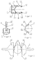
- a Retaining spring (15) provided with spring arms (16) on an inside of the Support arms (8) is mounted.
- the support arm (8) is in the transverse direction curved and has a retaining groove (17) in which the Federam (16) is stored.
- the elongated spring arms (16) are by a stiffening section (18) interconnected, which is transverse to the optical axis (6) in a plane in Area of the peripheral edge of the dome (7) extends.
- the stiffening section (18) has a plane parallel to the plane formed by the spring arms (16) extending middle section (19), each of which is symmetrical below Forming an obtuse angle connecting leg (20) to one extends dome-side end of the spring arm (16).
- the connecting legs (20) each form a right angle to the spring arms (16).
- the Stiffening section (18) serves to stiffen the radiation diaphragm (5) overall, in particular by investing the same in the area of a Bending line (21) this area is stabilized.
- the retaining spring (15) to the radiation diaphragm (5) in Position.
- the spring arms (16) extend in the direction of the reflector (2) easy opening, so that the hinge-like attached to the dome (7) Adapt the support arms (8) to this shape.
- the free ends of the spring arms (16) have inwardly directed lugs (22) which are located on the inside of a Extend leg of the hook-shaped element (12). Practice the noses (22) an outward pressure force, which is a safe and permanent Locking the hook-shaped elements (12) on the peripheral edge of the Effect reflector neck (14).
- the stamped part (9) points in one Support arms (8) oriented circumferential notches (23) on the edge form the bending line (21) and thus create a defined bending line.
- An alternative embodiment of the radiation diaphragm, not shown, can be used as Radiation shield for a high beam headlight. This aperture differs essentially from that described above in that the Shading sections (10) are omitted.
Landscapes
- Engineering & Computer Science (AREA)
- General Engineering & Computer Science (AREA)
- Non-Portable Lighting Devices Or Systems Thereof (AREA)
Abstract
Description
- Figur 1:
- Einen Vertikalschnitt durch einen Fahrzeugscheinwerfer,
- Figur 2:
- eine perspektivische Darstellung einer Strahlenblende,
- Figur 3:
- eine Seitenansicht der Strahlenblende,
- Figur 4:
- einen Horizontalschnitt durch die Strahlenblende,
- Figur 5:
- eine Rückansicht einer in der Strahlenblende gelagerten Haltefeder und
- Figur 6:
- eine abgewickelte Ansicht der Strahlenblende.
Claims (10)
- Fahrzeugscheinwerfer mit einem Reflektor, dem in Abstrahlrichtung eine eine Lampe abschirmende Strahlenblende vorgelagert ist, wobei die Strahlenblende mindestens zwei Tragarme aufweist zur Verbindung der Strahlenblende mit dem Randbereich einer Reflektoröffnung, dadurch gekennzeichnet, daß der Strahlenblende (5) eine Haltefeder (15) zugeordnet ist mit in Querrichtung unter Vorspannung stehenden und sich in Längsrichtung erstreckenden Federarmen (16).
- Fahrzeugscheinwerfer nach Anspruch 1, dadurch gekennzeichnet, daß sich die Haltefeder (15) auf einer der Lampe (3) zugekehrten Seite der Strahlenblende (5) erstreckt, wobei die Federarme (16) an einer Innenseite der Tragarme (8) anliegen.
- Fahrzeugscheinwerfer nach Anspruch 1 oder 2, dadurch gekennzeichnet, daß die Haltefeder (15) U-förmig ausgebildet ist mit sich entgegen der Abstrahlrichtung leicht öffnenden Federarmen (16).
- Fahrzeugscheinwerfer nach einem der Ansprüche 1 bis 3, dadurch gekennzeichnet, daß die Haltefeder (15) einen die Federarme (16) verbindenen Versteifungsabschnitt (18) aufweist, der sich im wesentlichen rechtwinklig zu den Federarmen (16) erstreckt.
- Fahrzeugscheinwerfer nach einem der Ansprüche 1 bis 4, dadurch gekennzeichnet, daß die Tragarme (8) jeweils eine Halterinne (17) aufweisen, in der die langgestreckten Federarme (16) gehaltert sind.
- Fahrzeugscheinwerfer nach einem der Ansprüche 1 bis 5, dadurch gekennzeichnet, daß der Versteifungsabschnitt (18) einen Mittelabschnitt (19) aufweist, der sich beabstandet und parallel zu einer durch die Federarme (16) gebildeten Ebene erstreckt.
- Fahrzeugscheinwerfer nach einem der Ansprüche 1 bis 6, dadurch gekennzeichnet, daß die Strahlenblende (5) eine Kuppel (7) aufweist, die einstückig mit den Tragarmen (8) verbunden ist.
- Fahrzeugscheinwerfer nach einem der Ansprüche 1 bis 7, dadurch gekennzeichnet, daß die Strahlenblende (5) in einem Umfangsbereich der Kuppel (7) voneinander beabstandete Einkerbungen (23) aufweist zur Ausbildung einer Biegelinie (21), um die der Tragarm (8) in eine Montageposition verschwenkbar ist, in der er zu der Kuppel (7) im wesentlichen einen rechten Winkel bildet.
- Fahrzeugscheinwerfer nach einem der Ansprüche 1 bis 8, dadurch gekennzeichnet, daß die Tragarme (8) jeweils an einem freien Ende ein hakenförmiges Element (12) aufweisen, an dessen Innenseite eine Nase (22) des Federarms (16) drückt zur rastenden Verbindung an den Umfangsrand der Reflektoröffnung.
- Fahrzeugscheinwerfer nach einem der Ansprüche 1 bis 9, dadurch gekennzeichnet, daß die Strahlenblende (5) aus einem glänzenden Aluminiumblech besteht.
Applications Claiming Priority (2)
| Application Number | Priority Date | Filing Date | Title |
|---|---|---|---|
| DE19831852A DE19831852A1 (de) | 1998-07-16 | 1998-07-16 | Fahrzeugscheinwerfer |
| DE19831852 | 1998-07-16 |
Publications (2)
| Publication Number | Publication Date |
|---|---|
| EP0972984A2 true EP0972984A2 (de) | 2000-01-19 |
| EP0972984A3 EP0972984A3 (de) | 2002-01-30 |
Family
ID=7874181
Family Applications (1)
| Application Number | Title | Priority Date | Filing Date |
|---|---|---|---|
| EP99112685A Ceased EP0972984A3 (de) | 1998-07-16 | 1999-07-02 | Fahrzeugscheinwerfer |
Country Status (2)
| Country | Link |
|---|---|
| EP (1) | EP0972984A3 (de) |
| DE (1) | DE19831852A1 (de) |
Cited By (1)
| Publication number | Priority date | Publication date | Assignee | Title |
|---|---|---|---|---|
| EP1262713A1 (de) | 2001-05-29 | 2002-12-04 | Valeo Vision | Anordnung zur Befestigung einer Lichtblende auf einem Reflektor und mit einer solchen Anordnung ausgerüsteter Scheinwerfer |
Families Citing this family (4)
| Publication number | Priority date | Publication date | Assignee | Title |
|---|---|---|---|---|
| DE20120417U1 (de) | 2001-12-18 | 2002-03-21 | Automotive Lighting Reutlingen GmbH, 72762 Reutlingen | Strahlenblende für Kfz-Scheinwerfer |
| DE10258535B4 (de) * | 2002-12-14 | 2008-04-03 | Volkswagen Ag | Fahrzeugscheinwerfer mit einer Strahlenblende |
| DE102004004651B3 (de) | 2004-01-29 | 2005-12-01 | Flowil International Lighting (Holding) B.V. | Lampe für allgemeine Beleuchtungszwecke |
| DE102004039524B4 (de) | 2004-08-14 | 2018-05-09 | Volkswagen Ag | Scheinwerfer mit einer Strahlenblende für ein Fahrzeug |
Family Cites Families (12)
| Publication number | Priority date | Publication date | Assignee | Title |
|---|---|---|---|---|
| US1954978A (en) * | 1931-02-28 | 1934-04-17 | Carl G Aldrich | Headlight |
| DE2351633A1 (de) * | 1973-10-15 | 1975-04-24 | Bosch Gmbh Robert | Anbauscheinwerfer, insbesondere fuer motorraeder |
| DE3124757C2 (de) * | 1981-06-24 | 1986-09-25 | Hans-Werner 2000 Hamburg Briese | Beleuchtungsvorrichtung mit einem Reflektor |
| DE8310535U1 (de) * | 1983-04-11 | 1983-09-08 | Comind S.p.A., Robassomero, Torino | Kraftfahrzeugscheinwerfer mit blendschutzschirm |
| IT8553633V0 (it) * | 1985-07-25 | 1985-07-25 | Carello Ind Spa | Proiettore particolarmente per autoveicoli con dispositivo oscuratore smontabile |
| US5067054A (en) * | 1989-10-11 | 1991-11-19 | Koito Manufacturing Co., Ltd. | Beam-forming shade for vehicular headlamp |
| JPH07109721B2 (ja) * | 1990-08-07 | 1995-11-22 | 株式会社小糸製作所 | 車輌用前照灯 |
| JP3013141B2 (ja) * | 1994-04-15 | 2000-02-28 | 株式会社小糸製作所 | 車輌用前照灯 |
| JP3007269B2 (ja) * | 1994-06-27 | 2000-02-07 | 株式会社小糸製作所 | 車両用前照灯 |
| JPH0883501A (ja) * | 1994-09-09 | 1996-03-26 | Ichikoh Ind Ltd | 車両用灯具 |
| US5497298A (en) * | 1994-12-12 | 1996-03-05 | General Motors Corporation | Headlamp assembly with coil spring bulb shield |
| FR2728654B1 (fr) * | 1994-12-21 | 1997-03-14 | Valeo Vision | Projecteur de vehicule automobile equipe d'un cache de lumiere directe d'aspect ameliore |
-
1998
- 1998-07-16 DE DE19831852A patent/DE19831852A1/de not_active Withdrawn
-
1999
- 1999-07-02 EP EP99112685A patent/EP0972984A3/de not_active Ceased
Cited By (2)
| Publication number | Priority date | Publication date | Assignee | Title |
|---|---|---|---|---|
| EP1262713A1 (de) | 2001-05-29 | 2002-12-04 | Valeo Vision | Anordnung zur Befestigung einer Lichtblende auf einem Reflektor und mit einer solchen Anordnung ausgerüsteter Scheinwerfer |
| FR2825447A1 (fr) | 2001-05-29 | 2002-12-06 | Valeo Vision | Agencement pour la fixation d'un dispositif d'occultation sur un reflecteur et projecteur de vehicule automobile equipe d'un tel agencement |
Also Published As
| Publication number | Publication date |
|---|---|
| EP0972984A3 (de) | 2002-01-30 |
| DE19831852A1 (de) | 2000-01-20 |
Similar Documents
| Publication | Publication Date | Title |
|---|---|---|
| EP0637715A1 (de) | Vorrichtung zur lösbaren Arretierung einer Lampe an einem Reflektor eines Fahrzeugscheinwefers | |
| DE69702478T2 (de) | Leuchtenbefestigung mit akkordeonförmig gefalteter Feder an der Karosserie eines Fahrzeuges | |
| DE3337826A1 (de) | Scheinwerfer fuer ein fahrrad oder dergleichen | |
| DE4228891B4 (de) | Einrichtung zur Verstellung von Elementen in Beleuchtungseinrichtungen, insbesondere Fahrzeugscheinwerfern | |
| EP3875857B1 (de) | Gargeräteleuchte mit formschlüssig gehaltenem lichtleitstab | |
| DE19957115C2 (de) | Beleuchtungseinrichtung für ein Motorrad | |
| DD299979A5 (de) | Scheinwerfer für Fahrzeuge | |
| EP0972984A2 (de) | Fahrzeugscheinwerfer | |
| DE19546271A1 (de) | Scheinwerfer für Fahrzeuge | |
| DE10029102B4 (de) | Vorrichtung zum Befestigen einer Leuchte | |
| DE10116957A1 (de) | Fahrzeugleuchte | |
| DE69931117T2 (de) | Kraftfahrzeugscheinwerfer mit querliegender Lampe und mit verbesserten Lampenmontagemitteln | |
| EP0548555B1 (de) | Scheinwerfer für Fahrzeuge | |
| EP0985871B1 (de) | Scheinwerfer und Verfahren zum Herstellen eines Scheinwerfers | |
| DE20107299U1 (de) | Scheinwerfer mit einem Gehäuse mit Halteklauen | |
| EP1043546B1 (de) | Lampenfassung für einen Fahrzeugscheinwerfer | |
| DE10303329A1 (de) | Lampenfassung für einen Kraftfahrzeugscheinwerfer und zur Aufnahme einer solchen Lampenfassung vorgesehener Scheinwerferreflektor | |
| DE4011703C1 (de) | ||
| DE69806445T2 (de) | Vorrichtung zur vorübergehenden Befestigung einer Beleuchtungs- oder Signaleinrichtung auf der Karosserie eines Kraftfahrzeuges | |
| DE19735325A1 (de) | Kraftfahrzeugscheinwerfer mit vereinfachtem Zusammenbau | |
| EP1595770B1 (de) | Kraftfahrzeug mit einer Leuchtmittelaufnahme für ein Aussenleuchtmittel | |
| DE10306867B4 (de) | Heckleuchte eines Kraftfahrzeuges | |
| EP0675021B1 (de) | Halteeinrichtung für einen verstellbaren Reflektor eines Fahrzeug-Scheinwerfers | |
| DE102023003983B4 (de) | Fahrzeug, Außenhautbauteil und Außenhautsystem | |
| EP1516781A2 (de) | Scheinwerfer für Fahrzeuge |
Legal Events
| Date | Code | Title | Description |
|---|---|---|---|
| PUAI | Public reference made under article 153(3) epc to a published international application that has entered the european phase |
Free format text: ORIGINAL CODE: 0009012 |
|
| AK | Designated contracting states |
Kind code of ref document: A2 Designated state(s): AT BE CH CY DE DK ES FI FR GB GR IE IT LI LU MC NL PT SE Kind code of ref document: A2 Designated state(s): DE ES FR GB IT |
|
| AX | Request for extension of the european patent |
Free format text: AL;LT;LV;MK;RO;SI |
|
| PUAL | Search report despatched |
Free format text: ORIGINAL CODE: 0009013 |
|
| AK | Designated contracting states |
Kind code of ref document: A3 Designated state(s): AT BE CH CY DE DK ES FI FR GB GR IE IT LI LU MC NL PT SE |
|
| AX | Request for extension of the european patent |
Free format text: AL;LT;LV;MK;RO;SI |
|
| 17P | Request for examination filed |
Effective date: 20020617 |
|
| AKX | Designation fees paid |
Free format text: DE ES FR GB IT |
|
| RAP1 | Party data changed (applicant data changed or rights of an application transferred) |
Owner name: HELLA KGAA HUECK & CO. |
|
| 17Q | First examination report despatched |
Effective date: 20050606 |
|
| STAA | Information on the status of an ep patent application or granted ep patent |
Free format text: STATUS: THE APPLICATION HAS BEEN REFUSED |
|
| 18R | Application refused |
Effective date: 20051022 |