EP0973053A2 - Dispositif d'ajustement de focalisation d'un dispositif opto-électronique - Google Patents
Dispositif d'ajustement de focalisation d'un dispositif opto-électronique Download PDFInfo
- Publication number
- EP0973053A2 EP0973053A2 EP99111514A EP99111514A EP0973053A2 EP 0973053 A2 EP0973053 A2 EP 0973053A2 EP 99111514 A EP99111514 A EP 99111514A EP 99111514 A EP99111514 A EP 99111514A EP 0973053 A2 EP0973053 A2 EP 0973053A2
- Authority
- EP
- European Patent Office
- Prior art keywords
- lens
- lever
- pivot lever
- swivel
- adjusting
- Prior art date
- Legal status (The legal status is an assumption and is not a legal conclusion. Google has not performed a legal analysis and makes no representation as to the accuracy of the status listed.)
- Withdrawn
Links
Images
Classifications
-
- G—PHYSICS
- G02—OPTICS
- G02B—OPTICAL ELEMENTS, SYSTEMS OR APPARATUS
- G02B7/00—Mountings, adjusting means, or light-tight connections, for optical elements
- G02B7/28—Systems for automatic generation of focusing signals
Definitions
- the present invention relates to a device for adjusting the focus position a light emitting element and a lens for Focusing the light emitted by the transmitting element optoelectronic device. Furthermore, the invention is based on an optoelectronic Device with such a device for adjustment the focus position.
- Devices of this type are used, for example, the focus position of light barriers, light buttons, bar code readers or other adjust optoelectronic devices.
- a pivot lever is provided, which is at one end of the pivot lever provided pivot axis is pivotable. While the lens in the middle of the swivel lever between it both free ends is arranged, engages on the opposite of the pivot axis End of the pivot lever on an actuator on the the pivot lever is adjustable about the pivot axis. In this way is the distance between the lens and that within the optoelectronic Device provided transmission element and thus the focus position the device adjustable.
- a disadvantage of the known devices is that the control element usually arranged transversely to the longitudinal extent of the pivot lever is and thus laterally relatively far beyond the pivot lever extends.
- the dimensions of such an adjustment device and thus also one provided with such an adjusting device optoelectronic device relatively large, which in today's Trend towards increasing miniaturization in practically all technical Areas is disadvantageous.
- a device for Adjusting the focus position of a light emitting element and a lens for focusing that emitted by the transmitting element Light-encompassing optoelectronic device with a swivel lever for receiving the transmitting element or the lens, the Swivel lever designed as a double-arm swivel lever and over a Adjusting element for adjusting the distance between the transmitting element and the lens and thus to adjust the focus position around a swivel is pivotable, the one arm of the pivot lever for receiving the lens or the transmission element is formed and the actuating element a portion of the attack on the other side of the swivel, attacks other arm of the pivot lever.
- the object is achieved by a device for Adjusting the focus position of a light emitting element and a lens for focusing that emitted by the transmitting element
- a device for Adjusting the focus position of a light emitting element and a lens for focusing that emitted by the transmitting element Light-encompassing optoelectronic device with a swivel lever for receiving the transmitting element or the lens, the Swivel lever via an adjusting element to adjust the distance between the transmitting element and the lens and thus for adjusting the focus position is pivotable about a swivel and the actuator extends along the longitudinal extent of the pivot lever.
- control element arranged on the one arm of the pivot lever Point of attack towards the other arm of the pivot lever there.
- This embodiment ensures that the control element extends practically completely along the pivot lever, so that a further reduction in the dimensions of the adjustment device according to the invention reached perpendicular to the longitudinal extent of the pivot lever becomes.
- control element is in particular electric motor, so preferably the axis of rotation of the motor essentially parallel to the longitudinal extent of the pivot lever run to get a space-optimized arrangement.
- the pivot lever can have a recess, in particular have an opening, part of the Control element extends into the recess. This can also a reduction in the dimensions of the device according to the invention can be reached in the plane of movement of the swivel lever because of Swivel lever and the control element, for example the housing of the Actuator, can interlock.
- the invention takes effect the control element via an eccentric on the swivel lever.
- the eccentric can, for example, on the axis of rotation Servomotor provided or can be operated manually from the outside.
- the swivel joint is preferably designed as a leaf spring swivel joint, because through such training, the cost of a corresponding device can be reduced. In principle, however, it is possible that any common swivel connections can be used.
- Swivel joint provided on a base part, on the pivot lever
- Positioning elements for unambiguously fixing the swivel lever in relation to of the base part are formed in at least two degrees of freedom. That is usually attached to or in an optoelectronic device or integrally formed with this base part thus forms the Articulation point for the swivel movement of the swivel lever.
- the Swivel lever After positioning the Swivel lever by setting the positioning elements is thus the Swivel lever can only be swiveled around the swivel joint and therefore the lens and the transmission element only with respect to their distance from each other adjustable. A lateral shift of the lens and the transmission element against each other is reliably prevented by the positioning elements.
- the positioning elements can include, for example, pins that for example in the leaf spring of the leaf spring swivel Intervene openings without play.
- other positioning elements can also be used be provided, the play-free fixing of the pivot lever with respect to the base part and in particular with regard to the leaf spring swivel joint ensure in at least two degrees of freedom.
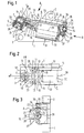
- a base part 1 with openings 2, via which they can be used, for example, with the housing of an optoelectronic Device can be connected.
- an extension 3 is formed with a bore 4 in which a version 38 is included.
- a transmission element 5 arranged in the form of a diode.
- On the inside of the hole 4 are in the longitudinal direction of the bore 4, projecting inwards Skids 39 or webs formed, which when inserting the socket 38 in the hole 4 are deformed or in the outside of the socket Cut 38.
- Through the runners 39 is a non-rotatable press fit Socket 38 in bore 4 with simultaneous possibility of displacement in Longitudinal direction of the bore 4 possible.
- the socket 38 has from the shoulder 3 laterally protruding pins 40, over which the socket 38 along the Skids 39 of the hole 4 can be moved. About this shift can first set the "focus zero" of the system to a defined one Position of the pivot lever 8 can be adjusted.
- a lens is located opposite the transmission element 5 in the radiation direction 6 provided in the area of the free end 7 of a pivot lever 8 is arranged.
- the pivot lever 8 has one at its free end 7 Recess 9 in which the lens 6 is attached. The stretches Recess 9 completely through the free end of the pivot lever 8 through, so that light emitted by the transmitting element 5 along an axis z pass through the lens 6 and the pivot lever 8 can.
- the pivot lever 8 is in its central region 10 via a swivel joint 11 forming leaf springs 12 connected so that the pivot lever 8 opposite the base part 1 is pivotable according to an arrow 13.
- this forms one double-armed swivel lever with a first arm 14, at the end the lens 6 is arranged, and with a second arm 15 which extends over the pivot 11 extends away from the first arm 14.
- the movement of the pivot lever 8 in the z direction is achieved by screwing 18 prevents through the leaf springs 12 in in the pivot lever 8 trained threaded holes 19 are screwed.
- screws 18 and threaded holes 19 can basically other suitable connection options, such as riveted connections, Adhesive connections, soldered connections, welded connections or the like can be used.
- the leaf springs 12 are with the approach 3 of the base part 1 by screws 20 connected, here also the connection by other suitable Connecting means, for example the connecting means just mentioned, can be made.
- the approach 3 also has positioning elements designed as pins 21, which in correspondingly formed openings in the leaf springs 12th intervene and thus a clear positioning between the leaf springs 12 and approach 3.
- pivot 23 is formed in a recess 23, in which a Pin 24 rotatably connected to the arm 15 of the pivot lever 8 Ball bearing 25 is arranged.
- the ball bearing 25 forms an engagement section 26 for an eccentric 27, that at the free end 28 of an axis of rotation 29 of an electric motor 30 arranged, in particular is pressed onto this.
- the eccentric 27 has a spherical outer surface 37, so that when the Swivel lever 8 around the pivot 11, the ball bearing 25 on the crowned Outer surface 37 of the eccentric 27 rolls.
- the motor 30 forms an adjusting element 31 together with the eccentric 27 for the pivot lever 8, via which the pivot lever 8 around the pivot joint 11 can be pivoted.
- the eccentric 27 and the motor 30 extend from the engagement section 26 of the arm 15 of the pivot lever 8 towards its arm 14, wherein the axis of rotation 29 of the motor 30 is substantially parallel to the Longitudinal extension of the pivot lever 8 runs.
- the arm 15 of the pivot lever 8 is one in particular to the axis of rotation 29 symmetrically formed opening 32 formed, in which a part 33 of the motor 30 extends into it.
- a guide designed as a pin 34 for a Coil spring trained compression spring 35 is provided under tension between the arm 15 of the pivot lever 8 and a projection 36 of the base part 1 is arranged so that the arm 15 due to the spring force is pushed away from the projection 36.
- a coil spring another suitable shape for the spring 35 can also be selected become.
- the spring 35 can in principle also be used as a tension spring be formed and in this case, for example, on the side of the recess 23 be attached to the arm 15.
- the spring 35 in an analogous manner on the arm 14 attack the pivot lever 8
- the housing of the motor 30 is cylindrical is formed and extending in the direction of the pivot lever 8 Region 33 of the cylindrical housing extends into the opening 32.
- the movement of the arm 15 causes the Swivel lever 8 around the pivot 11 so that the arm 14 together is moved with the lens 6 in the direction of the transmission element 5.
Landscapes
- Physics & Mathematics (AREA)
- General Physics & Mathematics (AREA)
- Optics & Photonics (AREA)
- Lens Barrels (AREA)
- Automatic Focus Adjustment (AREA)
Priority Applications (1)
| Application Number | Priority Date | Filing Date | Title |
|---|---|---|---|
| DE29924616U DE29924616U1 (de) | 1998-06-19 | 1999-06-14 | Vorrichtung zum Verstellen der Fokuslage einer optoelektronischen Vorrichtung |
Applications Claiming Priority (2)
| Application Number | Priority Date | Filing Date | Title |
|---|---|---|---|
| DE19827485A DE19827485A1 (de) | 1998-06-19 | 1998-06-19 | Vorrichtung zum Verstellen der Fokuslage einer optoelektronischen Vorrichtung |
| DE19827485 | 1998-06-19 |
Publications (2)
| Publication Number | Publication Date |
|---|---|
| EP0973053A2 true EP0973053A2 (fr) | 2000-01-19 |
| EP0973053A3 EP0973053A3 (fr) | 2003-07-02 |
Family
ID=7871479
Family Applications (1)
| Application Number | Title | Priority Date | Filing Date |
|---|---|---|---|
| EP99111514A Withdrawn EP0973053A3 (fr) | 1998-06-19 | 1999-06-14 | Dispositif d'ajustement de focalisation d'un dispositif opto-électronique |
Country Status (3)
| Country | Link |
|---|---|
| US (1) | US6147820A (fr) |
| EP (1) | EP0973053A3 (fr) |
| DE (1) | DE19827485A1 (fr) |
Families Citing this family (5)
| Publication number | Priority date | Publication date | Assignee | Title |
|---|---|---|---|---|
| US7546780B2 (en) * | 2005-09-30 | 2009-06-16 | Rockwell Automation Technologies, Inc. | Sensor mounting structure allowing for adjustment of sensor position |
| US7412900B2 (en) * | 2005-09-30 | 2008-08-19 | Rockwell Automation Technologies, Inc. | Sensor mounting structure with adjustable swivel ball and panel mounting mechanism |
| US7527437B2 (en) * | 2005-09-30 | 2009-05-05 | Rockwell Automation Technologies, Inc. | Sensor mounting structure with light pipe |
| US7415891B2 (en) * | 2005-09-30 | 2008-08-26 | Rockwell Automation Technologies, Inc. | Sensor mounting structure with snapping feature |
| DE102018120807A1 (de) * | 2018-08-27 | 2020-02-27 | Sick Ag | Fokusverstellbare Optik |
Family Cites Families (11)
| Publication number | Priority date | Publication date | Assignee | Title |
|---|---|---|---|---|
| US3071052A (en) * | 1959-04-29 | 1963-01-01 | Gauthier Gmbh A | Photographic camera with automatic exposure setting |
| CH598613A5 (en) * | 1976-04-21 | 1978-05-12 | Bolex Int Sa | Automatically focussed camera with optical baseline |
| US4615621A (en) * | 1982-04-02 | 1986-10-07 | Eaton Corporation | Auto-focus alignment and measurement system and method |
| NL8701526A (nl) * | 1987-06-30 | 1989-01-16 | Philips Nv | Inrichting voor het optisch aftasten van een roterende plaat. |
| JPH03237627A (ja) * | 1990-02-13 | 1991-10-23 | Matsushita Electric Ind Co Ltd | 対物レンズ駆動装置 |
| JPH04313824A (ja) * | 1991-04-12 | 1992-11-05 | Pioneer Electron Corp | 光学式情報読取装置におけるレンズ駆動装置 |
| KR930009683B1 (ko) * | 1991-05-16 | 1993-10-08 | 삼성전자 주식회사 | 광학계 구동장치 |
| JPH08167158A (ja) * | 1994-12-13 | 1996-06-25 | Sony Corp | 二軸アクチュエータ |
| US5912774A (en) * | 1995-07-28 | 1999-06-15 | Canon Kabushiki Kaisha | Lens moving mechanism for finely moving a portion of an objective lens by rotating a holding member |
| JPH09311262A (ja) * | 1996-05-21 | 1997-12-02 | Hitachi Denshi Ltd | 顕微鏡用オートフォーカス機構 |
| DE19702573C2 (de) * | 1997-01-24 | 2003-11-13 | Sick Ag | Optische Einrichtung mit einer justierbaren Haltevorrichtung |
-
1998
- 1998-06-19 DE DE19827485A patent/DE19827485A1/de not_active Withdrawn
-
1999
- 1999-06-14 EP EP99111514A patent/EP0973053A3/fr not_active Withdrawn
- 1999-06-17 US US09/335,386 patent/US6147820A/en not_active Expired - Lifetime
Also Published As
| Publication number | Publication date |
|---|---|
| US6147820A (en) | 2000-11-14 |
| DE19827485A1 (de) | 1999-12-23 |
| EP0973053A3 (fr) | 2003-07-02 |
Similar Documents
| Publication | Publication Date | Title |
|---|---|---|
| DE69713297T2 (de) | Scharnier mit elastisch überdehnbarem offenanschlag sowie eine ein derartiges scharnier umfassende brille | |
| DE69700120T2 (de) | Federkontaktelement | |
| EP1852943A1 (fr) | Contact d'épreuve | |
| CH673898A5 (fr) | ||
| DE10297096T5 (de) | Scharnierkonstruktion und Scharnierbetätigungsvorrichtung, insbesondere für einen Seitenspiegel eines Motorfahrzeugs | |
| WO2018208239A1 (fr) | Dispositif de retenue pour façade de tiroir | |
| EP0356789B1 (fr) | Interrupteur électrique, en particulier monté sur la colonne de direction d'un véhicule | |
| DE3405654C2 (de) | Betätigungsvorrichtung für Schalteinrichtungen | |
| EP0973053A2 (fr) | Dispositif d'ajustement de focalisation d'un dispositif opto-électronique | |
| EP0490023A1 (fr) | Dispositif de bouton-poussoirs | |
| WO2018208238A1 (fr) | Dispositif de retenue destiné à une façade de tiroir | |
| EP0622718A1 (fr) | Levier de commande | |
| DE3021598A1 (de) | Drucktastenschalter | |
| DE102005009308A1 (de) | Identifikationseinrichtung | |
| EP0525507A2 (fr) | Dispositif de réglage d'un actionneur pour régler la cylindrée d'un machine hydrostatique | |
| DD208871A1 (de) | Fokussieranordnung fuer spiegelteleskope | |
| DE29924616U1 (de) | Vorrichtung zum Verstellen der Fokuslage einer optoelektronischen Vorrichtung | |
| DE4209668A1 (de) | Steuergerät, insbesondere zur Fernbedienung von hydraulischen Komponenten | |
| DE60201309T2 (de) | Anordnung zum Umwandeln einer hin- und hergehenden Bewegung in eine schwingende Bewegung | |
| EP1870914A2 (fr) | Interrupteur de fin de course doté d'un élément de commutation | |
| EP0499948B1 (fr) | Rétroviseur intérieur de véhicule anti-éblouissant | |
| DE19741926C1 (de) | Schalter | |
| DE102024138996B3 (de) | Elektrisches Schaltgerät mit formgefedertem Druckstück | |
| EP1165344A1 (fr) | Dispositif de reglage | |
| EP1736624A2 (fr) | Transmission pour une poignée ou barre anti-panique |
Legal Events
| Date | Code | Title | Description |
|---|---|---|---|
| PUAI | Public reference made under article 153(3) epc to a published international application that has entered the european phase |
Free format text: ORIGINAL CODE: 0009012 |
|
| AK | Designated contracting states |
Kind code of ref document: A2 Designated state(s): AT BE CH CY DE DK ES FI FR GB GR IE IT LI LU MC NL PT SE |
|
| AX | Request for extension of the european patent |
Free format text: AL;LT;LV;MK;RO;SI |
|
| PUAL | Search report despatched |
Free format text: ORIGINAL CODE: 0009013 |
|
| AK | Designated contracting states |
Designated state(s): AT BE CH CY DE DK ES FI FR GB GR IE IT LI LU MC NL PT SE |
|
| AX | Request for extension of the european patent |
Extension state: AL LT LV MK RO SI |
|
| RIC1 | Information provided on ipc code assigned before grant |
Ipc: 7G 02B 7/08 B Ipc: 7G 02B 7/28 A |
|
| 17P | Request for examination filed |
Effective date: 20030811 |
|
| 17Q | First examination report despatched |
Effective date: 20030909 |
|
| AKX | Designation fees paid |
Designated state(s): AT DE ES FR GB IT NL |
|
| STAA | Information on the status of an ep patent application or granted ep patent |
Free format text: STATUS: THE APPLICATION IS DEEMED TO BE WITHDRAWN |
|
| 18D | Application deemed to be withdrawn |
Effective date: 20040420 |