EP0973220A2 - Vorrichtung und Verfahren zur Steuerung einer Reformierungsanlage - Google Patents
Vorrichtung und Verfahren zur Steuerung einer Reformierungsanlage Download PDFInfo
- Publication number
- EP0973220A2 EP0973220A2 EP99113928A EP99113928A EP0973220A2 EP 0973220 A2 EP0973220 A2 EP 0973220A2 EP 99113928 A EP99113928 A EP 99113928A EP 99113928 A EP99113928 A EP 99113928A EP 0973220 A2 EP0973220 A2 EP 0973220A2
- Authority
- EP
- European Patent Office
- Prior art keywords
- amount
- heat
- fuel
- oxidizer
- temperature
- Prior art date
- Legal status (The legal status is an assumption and is not a legal conclusion. Google has not performed a legal analysis and makes no representation as to the accuracy of the status listed.)
- Withdrawn
Links
Images


Classifications
-
- H—ELECTRICITY
- H01—ELECTRIC ELEMENTS
- H01M—PROCESSES OR MEANS, e.g. BATTERIES, FOR THE DIRECT CONVERSION OF CHEMICAL ENERGY INTO ELECTRICAL ENERGY
- H01M8/00—Fuel cells; Manufacture thereof
- H01M8/06—Combination of fuel cells with means for production of reactants or for treatment of residues
- H01M8/0606—Combination of fuel cells with means for production of reactants or for treatment of residues with means for production of gaseous reactants
- H01M8/0612—Combination of fuel cells with means for production of reactants or for treatment of residues with means for production of gaseous reactants from carbon-containing material
-
- C—CHEMISTRY; METALLURGY
- C01—INORGANIC CHEMISTRY
- C01B—NON-METALLIC ELEMENTS; COMPOUNDS THEREOF; METALLOIDS OR COMPOUNDS THEREOF NOT COVERED BY SUBCLASS C01C
- C01B3/00—Hydrogen; Gaseous mixtures containing hydrogen; Separation of hydrogen from mixtures containing it; Purification of hydrogen; Reversible storage of hydrogen
- C01B3/02—Production of hydrogen; Production of gaseous mixtures containing hydrogen
- C01B3/32—Production of hydrogen; Production of gaseous mixtures containing hydrogen by reaction of gaseous or liquid organic compounds with gasifying agents, e.g. water, carbon dioxide or air
- C01B3/323—Catalytic reaction of gaseous or liquid organic compounds other than hydrocarbons with gasifying agents
-
- C—CHEMISTRY; METALLURGY
- C01—INORGANIC CHEMISTRY
- C01B—NON-METALLIC ELEMENTS; COMPOUNDS THEREOF; METALLOIDS OR COMPOUNDS THEREOF NOT COVERED BY SUBCLASS C01C
- C01B3/00—Hydrogen; Gaseous mixtures containing hydrogen; Separation of hydrogen from mixtures containing it; Purification of hydrogen; Reversible storage of hydrogen
- C01B3/02—Production of hydrogen; Production of gaseous mixtures containing hydrogen
- C01B3/32—Production of hydrogen; Production of gaseous mixtures containing hydrogen by reaction of gaseous or liquid organic compounds with gasifying agents, e.g. water, carbon dioxide or air
- C01B3/34—Production of hydrogen; Production of gaseous mixtures containing hydrogen by reaction of gaseous or liquid organic compounds with gasifying agents, e.g. water, carbon dioxide or air by reaction of hydrocarbons with gasifying agents
- C01B3/38—Production of hydrogen; Production of gaseous mixtures containing hydrogen by reaction of gaseous or liquid organic compounds with gasifying agents, e.g. water, carbon dioxide or air by reaction of hydrocarbons with gasifying agents using catalysts
-
- C—CHEMISTRY; METALLURGY
- C01—INORGANIC CHEMISTRY
- C01B—NON-METALLIC ELEMENTS; COMPOUNDS THEREOF; METALLOIDS OR COMPOUNDS THEREOF NOT COVERED BY SUBCLASS C01C
- C01B3/00—Hydrogen; Gaseous mixtures containing hydrogen; Separation of hydrogen from mixtures containing it; Purification of hydrogen; Reversible storage of hydrogen
- C01B3/50—Separation of hydrogen or hydrogen-containing gases from gaseous mixtures, e.g. purification
- C01B3/56—Separation of hydrogen or hydrogen-containing gases from gaseous mixtures, e.g. purification by contacting with solids; Regeneration of used solids
- C01B3/58—Separation of hydrogen or hydrogen-containing gases from gaseous mixtures, e.g. purification by contacting with solids; Regeneration of used solids including a catalytic reaction
- C01B3/583—Separation of hydrogen or hydrogen-containing gases from gaseous mixtures, e.g. purification by contacting with solids; Regeneration of used solids including a catalytic reaction the reaction being the selective oxidation of carbon monoxide
-
- C—CHEMISTRY; METALLURGY
- C01—INORGANIC CHEMISTRY
- C01B—NON-METALLIC ELEMENTS; COMPOUNDS THEREOF; METALLOIDS OR COMPOUNDS THEREOF NOT COVERED BY SUBCLASS C01C
- C01B2203/00—Integrated processes for the production of hydrogen or synthesis gas
- C01B2203/02—Processes for making hydrogen or synthesis gas
- C01B2203/0205—Processes for making hydrogen or synthesis gas containing a reforming step
- C01B2203/0227—Processes for making hydrogen or synthesis gas containing a reforming step containing a catalytic reforming step
- C01B2203/0244—Processes for making hydrogen or synthesis gas containing a reforming step containing a catalytic reforming step the reforming step being an autothermal reforming step, e.g. secondary reforming processes
-
- C—CHEMISTRY; METALLURGY
- C01—INORGANIC CHEMISTRY
- C01B—NON-METALLIC ELEMENTS; COMPOUNDS THEREOF; METALLOIDS OR COMPOUNDS THEREOF NOT COVERED BY SUBCLASS C01C
- C01B2203/00—Integrated processes for the production of hydrogen or synthesis gas
- C01B2203/04—Integrated processes for the production of hydrogen or synthesis gas containing a purification step for the hydrogen or the synthesis gas
- C01B2203/0435—Catalytic purification
- C01B2203/044—Selective oxidation of carbon monoxide
-
- C—CHEMISTRY; METALLURGY
- C01—INORGANIC CHEMISTRY
- C01B—NON-METALLIC ELEMENTS; COMPOUNDS THEREOF; METALLOIDS OR COMPOUNDS THEREOF NOT COVERED BY SUBCLASS C01C
- C01B2203/00—Integrated processes for the production of hydrogen or synthesis gas
- C01B2203/04—Integrated processes for the production of hydrogen or synthesis gas containing a purification step for the hydrogen or the synthesis gas
- C01B2203/0465—Composition of the impurity
- C01B2203/047—Composition of the impurity the impurity being carbon monoxide
-
- C—CHEMISTRY; METALLURGY
- C01—INORGANIC CHEMISTRY
- C01B—NON-METALLIC ELEMENTS; COMPOUNDS THEREOF; METALLOIDS OR COMPOUNDS THEREOF NOT COVERED BY SUBCLASS C01C
- C01B2203/00—Integrated processes for the production of hydrogen or synthesis gas
- C01B2203/06—Integration with other chemical processes
- C01B2203/066—Integration with other chemical processes with fuel cells
-
- C—CHEMISTRY; METALLURGY
- C01—INORGANIC CHEMISTRY
- C01B—NON-METALLIC ELEMENTS; COMPOUNDS THEREOF; METALLOIDS OR COMPOUNDS THEREOF NOT COVERED BY SUBCLASS C01C
- C01B2203/00—Integrated processes for the production of hydrogen or synthesis gas
- C01B2203/08—Methods of heating or cooling
- C01B2203/0805—Methods of heating the process for making hydrogen or synthesis gas
- C01B2203/0811—Methods of heating the process for making hydrogen or synthesis gas by combustion of fuel
-
- C—CHEMISTRY; METALLURGY
- C01—INORGANIC CHEMISTRY
- C01B—NON-METALLIC ELEMENTS; COMPOUNDS THEREOF; METALLOIDS OR COMPOUNDS THEREOF NOT COVERED BY SUBCLASS C01C
- C01B2203/00—Integrated processes for the production of hydrogen or synthesis gas
- C01B2203/08—Methods of heating or cooling
- C01B2203/0805—Methods of heating the process for making hydrogen or synthesis gas
- C01B2203/0838—Methods of heating the process for making hydrogen or synthesis gas by heat exchange with exothermic reactions, other than by combustion of fuel
- C01B2203/0844—Methods of heating the process for making hydrogen or synthesis gas by heat exchange with exothermic reactions, other than by combustion of fuel the non-combustive exothermic reaction being another reforming reaction as defined in groups C01B2203/02 - C01B2203/0294
-
- C—CHEMISTRY; METALLURGY
- C01—INORGANIC CHEMISTRY
- C01B—NON-METALLIC ELEMENTS; COMPOUNDS THEREOF; METALLOIDS OR COMPOUNDS THEREOF NOT COVERED BY SUBCLASS C01C
- C01B2203/00—Integrated processes for the production of hydrogen or synthesis gas
- C01B2203/08—Methods of heating or cooling
- C01B2203/0805—Methods of heating the process for making hydrogen or synthesis gas
- C01B2203/0866—Methods of heating the process for making hydrogen or synthesis gas by combination of different heating methods
-
- C—CHEMISTRY; METALLURGY
- C01—INORGANIC CHEMISTRY
- C01B—NON-METALLIC ELEMENTS; COMPOUNDS THEREOF; METALLOIDS OR COMPOUNDS THEREOF NOT COVERED BY SUBCLASS C01C
- C01B2203/00—Integrated processes for the production of hydrogen or synthesis gas
- C01B2203/10—Catalysts for performing the hydrogen forming reactions
- C01B2203/1041—Composition of the catalyst
- C01B2203/1076—Copper or zinc-based catalysts
-
- C—CHEMISTRY; METALLURGY
- C01—INORGANIC CHEMISTRY
- C01B—NON-METALLIC ELEMENTS; COMPOUNDS THEREOF; METALLOIDS OR COMPOUNDS THEREOF NOT COVERED BY SUBCLASS C01C
- C01B2203/00—Integrated processes for the production of hydrogen or synthesis gas
- C01B2203/12—Feeding the process for making hydrogen or synthesis gas
- C01B2203/1205—Composition of the feed
- C01B2203/1211—Organic compounds or organic mixtures used in the process for making hydrogen or synthesis gas
- C01B2203/1217—Alcohols
- C01B2203/1223—Methanol
-
- C—CHEMISTRY; METALLURGY
- C01—INORGANIC CHEMISTRY
- C01B—NON-METALLIC ELEMENTS; COMPOUNDS THEREOF; METALLOIDS OR COMPOUNDS THEREOF NOT COVERED BY SUBCLASS C01C
- C01B2203/00—Integrated processes for the production of hydrogen or synthesis gas
- C01B2203/12—Feeding the process for making hydrogen or synthesis gas
- C01B2203/1288—Evaporation of one or more of the different feed components
-
- C—CHEMISTRY; METALLURGY
- C01—INORGANIC CHEMISTRY
- C01B—NON-METALLIC ELEMENTS; COMPOUNDS THEREOF; METALLOIDS OR COMPOUNDS THEREOF NOT COVERED BY SUBCLASS C01C
- C01B2203/00—Integrated processes for the production of hydrogen or synthesis gas
- C01B2203/14—Details of the flowsheet
- C01B2203/142—At least two reforming, decomposition or partial oxidation steps in series
-
- C—CHEMISTRY; METALLURGY
- C01—INORGANIC CHEMISTRY
- C01B—NON-METALLIC ELEMENTS; COMPOUNDS THEREOF; METALLOIDS OR COMPOUNDS THEREOF NOT COVERED BY SUBCLASS C01C
- C01B2203/00—Integrated processes for the production of hydrogen or synthesis gas
- C01B2203/16—Controlling the process
- C01B2203/1614—Controlling the temperature
- C01B2203/1619—Measuring the temperature
-
- C—CHEMISTRY; METALLURGY
- C01—INORGANIC CHEMISTRY
- C01B—NON-METALLIC ELEMENTS; COMPOUNDS THEREOF; METALLOIDS OR COMPOUNDS THEREOF NOT COVERED BY SUBCLASS C01C
- C01B2203/00—Integrated processes for the production of hydrogen or synthesis gas
- C01B2203/16—Controlling the process
- C01B2203/1685—Control based on demand of downstream process
-
- C—CHEMISTRY; METALLURGY
- C01—INORGANIC CHEMISTRY
- C01B—NON-METALLIC ELEMENTS; COMPOUNDS THEREOF; METALLOIDS OR COMPOUNDS THEREOF NOT COVERED BY SUBCLASS C01C
- C01B2203/00—Integrated processes for the production of hydrogen or synthesis gas
- C01B2203/16—Controlling the process
- C01B2203/169—Controlling the feed
-
- C—CHEMISTRY; METALLURGY
- C01—INORGANIC CHEMISTRY
- C01B—NON-METALLIC ELEMENTS; COMPOUNDS THEREOF; METALLOIDS OR COMPOUNDS THEREOF NOT COVERED BY SUBCLASS C01C
- C01B2203/00—Integrated processes for the production of hydrogen or synthesis gas
- C01B2203/16—Controlling the process
- C01B2203/1695—Adjusting the feed of the combustion
-
- C—CHEMISTRY; METALLURGY
- C01—INORGANIC CHEMISTRY
- C01B—NON-METALLIC ELEMENTS; COMPOUNDS THEREOF; METALLOIDS OR COMPOUNDS THEREOF NOT COVERED BY SUBCLASS C01C
- C01B2203/00—Integrated processes for the production of hydrogen or synthesis gas
- C01B2203/80—Aspect of integrated processes for the production of hydrogen or synthesis gas not covered by groups C01B2203/02 - C01B2203/1695
- C01B2203/82—Several process steps of C01B2203/02 - C01B2203/08 integrated into a single apparatus
-
- Y—GENERAL TAGGING OF NEW TECHNOLOGICAL DEVELOPMENTS; GENERAL TAGGING OF CROSS-SECTIONAL TECHNOLOGIES SPANNING OVER SEVERAL SECTIONS OF THE IPC; TECHNICAL SUBJECTS COVERED BY FORMER USPC CROSS-REFERENCE ART COLLECTIONS [XRACs] AND DIGESTS
- Y02—TECHNOLOGIES OR APPLICATIONS FOR MITIGATION OR ADAPTATION AGAINST CLIMATE CHANGE
- Y02E—REDUCTION OF GREENHOUSE GAS [GHG] EMISSIONS, RELATED TO ENERGY GENERATION, TRANSMISSION OR DISTRIBUTION
- Y02E60/00—Enabling technologies; Technologies with a potential or indirect contribution to GHG emissions mitigation
- Y02E60/30—Hydrogen technology
- Y02E60/50—Fuel cells
Definitions
- the present invention relates to a reformer for reforming reformate fuel such as methyl alcohol and water into desired fuel such as gas with a high concentration of hydrogen and, more particularly, to a device and a method for controlling the reformer.
- a reformer that produces reformate gas mainly composed of hydrogen from methyl alcohol (methanol) and water.
- This reformer employs copper alloy and the like as a catalyst.
- the catalyst is at a temperature lower than its activation temperature (for example, about 280°C)
- methanol is not reformed sufficiently, and there is a large amount of methanol resides in the reformate gas.
- the reforming reaction of methanol is an endothermic reaction. Therefore, while the catalyst is maintained at the activation temperature, heat is supplied from the outside so as to promote the reforming reaction.
- the heat generated in the combustion portion is used to heat the liquid mixture of methanol and water, whereby the mixture becomes vapor of a predetermined temperature.
- the vapor (the mixture of methanol and water) is supplied to the reforming portion.
- the reaction in the reformer needs to be controlled in accordance with fluctuations in the load applied to the fuel cell.
- the amount of reformate gas produced needs to be increased with increases in load, whereas the amount of reformate gas produced needs to be reduced with decreases in load.
- the amount of the raw material fed to the reforming portion that is, the amount of the vapor mixture of methanol and water, is increased and reduced, respectively.
- the amount of heat required to generate the vapor mixture of methanol and water of a target temperature needs to be increased and reduced respectively.
- the amount of heat required to generate the vapor mixture of methanol and water can be controlled by increasing or reducing an amount of fuel (methanol and the like) that is supplied to the combustion portion for heating purposes.
- the burner for heating the raw material and the generation of heat based on the oxidizing catalyst exhibit a certain response delay in generating heat.
- the suitable heating control cannot be performed easily in accordance with instantaneous fluctuations in load. That is, in case of an abrupt increase in load, the amount of heat generated in the combustion portion is insufficient with respect to the amount of methanol and water that needs to be heated.
- the raw material and the catalyst fall in temperature and the reforming reaction proceeds slowly, increasing the amount of residual methanol in the reformate gas.
- the invention disclosed in Japanese Published Patent No. HEI 7-105240 controls temperature in accordance with fluctuations in the load by controlling a proportion of water in the raw material introduced into the reformer. That is, if the amount of water mixed into the raw material is reduced, the surplus amount of heat required to heat and vaporize the water decreases. As a result, the vapor mixture of methanol and water, which is the raw material, rises in temperature. Conversely, if the amount of water is increased, the surplus amount of heat required to heat and vaporize the water increases. As a result, the raw material falls in temperature.
- the aforementioned method is based on a premise that the amount of heat generated by fuel combustion remains constant, and consumes part of the thus-generated heat for the purpose of heating and vaporizing water.
- the amount of heat generated by fuel combustion is maintained at a level exceeding a theoretically suitable amount of heat. Consequently, the fuel combustion generates an amount of heat exceeding the amount actually required to reform the reformate fuel. Thus, fuel is consumed unnecessarily.
- the present invention has been made in consideration of the above-described circumstances. It is an object of the present invention to provide a device and a method for directly controlling an amount of heat generated in a heating portion of a reformer so as to maintain reformate fuel at a temperature required for a reforming reaction, and to cause the reforming reaction to proceed in a suitable manner without adversely affecting fuel consumption.
- embodiments of the present invention control fuel and an oxidizer on the basis of various factors, which range from the supply of fuel and the oxidizer to a heat generating portion for heating reformate fuel to combustion thereof and generation of heat.
- a device for controlling a reformer for producing reformate gas by reforming a raw material introduced into the reformer comprises a heater provided in the reformer to heat the raw material introduced into the reformer using heat generated in a reaction of heat fuel (supplied to the heater) with an oxidizer.
- the device further comprises a control system that calculates an amount of the raw material required to produce a desired amount reformate gas, and that determines at least one of an amount of the heat fuel supplied to the heater and an amount of the oxidizer, based on the determined amount of the raw material.
- both of the amount of the heat fuel and the amount of the oxidizer can be determined, based on the determined amount of the raw material.
- the oxidation of heat fuel generates an amount of heat corresponding to a change in the amount of reforming reaction requirement. Therefore, the present invention can prevent the temperature of the reforming reaction from fluctuating, to continuously maintain the reforming reaction in a favorable state.
- control system of the device can determine an amount of the heat fuel and an amount of the oxidizer, based on the amount of reforming reaction requirement and a desired ratio between the amount of heat fuel and the amount of the oxidizer.
- the desired ratio is preferably an optimal ratio.
- the device can comprise a detector that detects a ratio between the amount of heat fuel and the amount of the oxidizer.
- the control system can change at least one of the amount of heat fuel and the amount of the oxidizer such that the detected ratio becomes the desired ratio.
- the temperature of the reforming reaction can be controlled with higher precision.
- the device can comprise a temperature detector that detects a temperature of the heater.
- the control system can change one of the amount of the heat fuel and the amount of the oxidizer based on the detected temperature of the heater.
- the amount of heat generated in the reaction of the heat fuel with the oxidizer is controlled in accordance with a temperature of the heating portion, so that the heating portion can be maintained at a target temperature.
- the device can comprise a temperature detector that detects a temperature of the heater, and a detector that detects a change in the amount of heat generated in the heater as a result of a change in amount of the heat fuel that is supplied or in amount of the oxidizer.
- the control system can change one of the amount of the heat fuel and the amount of the oxidizer, based on the detected change in the amount of heat.
- the amounts of the heat fuel and the oxidizer are controlled, taking into account that there is a delay between a change in the amount of the heat fuel supplied to the heating portion or in amount of the oxidizer and a change in the amount of heat subsequently generated.
- the temperature of the heating portion can be prevented from fluctuating, so that the reforming reaction can be maintained in an appropriate state.
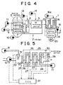
- a reformer 2 is connected to an anode 15 side of a fuel cell 1
- the reformer 2 reforms a mixture of methanol as reformate fuel and water into carbon dioxide and hydrogen.
- the reformer 2 is equipped with a heating portion 3 for heating the reformate fuel, a reforming portion 4 and a carbon monoxide (CO) oxidizing portion 5.
- the heating portion 3 generates vapor of the mixture of methanol and water by heating reformate fuel.
- the heating portion 3 comprises a combustion portion 6 for generating heat for heating the reformate fuel and a vaporizing portion 7 for vaporizing the reformate fuel using the heat generated by the combustion portion 6.
- the combustion portion 6 may be configured such that a burner causes heat fuel to burn or that a catalyst oxidizes heat fuel.
- a pump 8 for feeding methanol, which is an example of a suitable heat fuel is connected to the combustion portion 6 via an injector 9.
- an air feed portion 10 feeds air, which is an example of a suitable oxidizer.
- the air feed portion 10 is typically an air pump.
- a pump 11 serving as a reformate fuel feed portion for feeding the liquid mixture of methanol and water, is connected to the vaporizing portion 7.
- the vaporizing portion 7 is coupled to the combustion portion 6 such that heat can be transmitted therebetween.
- the reforming portion 4 generates gas with a high concentration of hydrogen, mainly by a reforming reaction of methanol with water. More specifically, a copper-based catalyst with an activation temperature of 280°C is typically used to generate reformate gas substantially comprising hydrogen gas, by a reforming reaction represented by equation (1) shown below. CH 3 OH + H 2 O ⁇ CO 2 + 3H 2
- the reforming portion 4 generates hydrogen gas and heat by a partially oxidizing reaction of methanol.
- air is fed from the air feed portion 13 to the reforming portion 4.
- the reforming reaction represented by the above equation (1) is an endothermic reaction.
- the partially oxidizing reaction is represented by equation (2) shown below is an exothermic reaction. Therefore, the temperature of the reforming portion 4 is kept substantially constant by balancing the endothermic and exothermic values.
- the reforming reaction represented by the equation (1) and the partially oxidizing reaction represented by the equation (2) occur only in ideal circumstances. Also, carbon dioxide is reversibly changed into carbon monoxide. Therefore, the inclusion of some carbon monoxide into the reformate gas is inevitable. Because carbon monoxide poisons a catalyst at the anode 15 of the fuel cell 1, the CO oxidizing portion 5 is provided so as to reduce the carbon monoxide. The CO oxidizing portion 5 is provided with a CO oxidizing catalyst and an air feed portion 14. The reformate gas generated in the reforming portion 4 is flowed through the CO oxidizing portion 5 so that the carbon monoxide contained in the reformate gas is oxidized by oxygen contained in air.
- the fuel cell 1 comprises a plurality of unit cells that are interconnected to one another.
- each unit cell can have a construction wherein a high-molecular electrolyte film permeable to protons is interposed between the anode 15 and a cathode 16.
- Each of the anode 15 and cathode 16 comprise a diffusion layer and a reaction layer.
- the reaction layer at the anode 15 has a porous structure wherein a catalyst material such as platinum, platinum alloy or ruthenium is carried, for example, on a carbon support.
- the anode 15 communicates with the reformer 2, to which reformate gas mainly containing hydrogen gas is fed.
- An air feed portion 16 such as a pump is connected to the cathode 16 so as to feed oxygen, which reacts with hydrogen in the reformate gas.
- External loads such as a battery 17 and an inverter 18 are connected to the respective electrodes 15 and 16 to form a closed circuit.
- the closed circuit incorporates a current sensor 19.
- a motor 20 is connected to the inverter 18.
- the motor 20 can serve as a power source for driving a vehicle.
- Fig. 5 shows an exemplary embodiment of the aforementioned heating portion 3 in conjunction with a control system.
- the combustion portion 6 includes a combustion chamber 21.
- combustion methanol as heating fuel
- the injector 9 is disposed on an inlet side of the combustion chamber 21, and combustion methanol is sprayed into the combustion chamber 21 through the injector 9.
- an air feed port 22 is formed on the inlet side of the combustion chamber 21.
- the air feed port 22 opens near to where combustion methanol is sprayed.
- An air pump 10 is connected to the air feed port 22.
- a heat exchanger 12 (Fig. 4) is disposed inside the combustion chamber 21.
- the heat exchanger 12 has a plurality of vaporization pipes 23 that air-tightly penetrate the combustion chamber 21.
- the vaporization pipes 23 communicate at one end with a liquid feed pipe 24, and at the other end with a vapor pipe 25.
- an oxidizing catalyst 26 is installed in a portion of an outer peripheral face of each of the vaporization pipes 23, which portion is located inside the combustion chamber 21.
- the combustion methanol fed into the combustion chamber 21 is oxidized by oxygen contained in air and then generates heat.
- a temperature sensor 27 for detecting the temperature resulting from this combustion is attached to each of the catalysts 26, or to each of the vaporization pipes 23.
- An exhaust pipe 28 is connected to a downstream side of the combustion chamber 21.
- An air-fuel ratio sensor (A/F sensor) 29 is disposed at an end portion of the exhaust pipe 28 on the side of the combustion chamber 21.
- the A/F sensor 29 outputs an electric signal corresponding to a concentration of oxygen in exhaust gas. Accordingly, the ratio A/F (air/fuel) of oxygen to the combustion methanol fed into the combustion portion 6 can be detected.
- the liquid feed pipe 24 feeds the liquid mixture of methanol as reformate fuel and water to the vaporization pipes 23.
- the liquid feed pipe 24 is connected to the liquid feed pump 11, which constitutes the reformate fuel feed portion.
- the vapor pipe 25 constitutes a tubular passage for feeding the vapor mixture of water and methanol generated in the vaporization pipes 23 to the reforming portion 4.
- a vapor temperature sensor 30 for detecting the temperature of vapor is disposed inside the vaporization pipe 25.
- the control system comprises one or more controllers, such as an electronic control unit (ECU) 31, to electrically control the respective pumps 8, 10 and 11 and suitably adjust discharge amounts thereof.
- the electronic control unit 31 comprises a microcomputer, which typically includes a central processing unit (CPU), storage devices (RAM, ROM) and an I/O interface. Detection signals from the respective sensors 27, 29 and 30 are inputted to the electronic control unit 31 as control data. Furthermore, the current sensor 19 for detecting a load of the fuel cell 1 outputs a detection signal, which is inputted to the electronic control unit 31.
- the liquid feed pump 11 feeds the liquid mixture of methanol as reformate fuel and water to the vaporization pipes 23 through the liquid feed pipe 24.
- Combustion methanol is sprayed from the injector 9 into the combustion chamber 21, to which air is fed by the air pump 10.
- the combustion methanol and air undergo an oxidizing reaction (i.e., burn) in the oxidizing catalyst 26 and generate heat.
- This heat in turn heats the vaporization pipes 23, and the liquid mixture contained in the vaporization pipes 23 is vaporized so that the vapor mixture of water and methanol is generated.
- the exhaust gas generated by combustion is discharged to the outside through the exhaust pipe 28.
- the vapor mixture generated in the vaporization pipes 23 is delivered to the reforming portion 4 through the vapor pipe 25.
- the copper-based catalyst provided in the reforming portion 4 causes a reforming reaction of methanol with water. Consequently, reformate gas substantially comprising hydrogen gas and carbon dioxide gas is generated.
- reformate gas substantially comprising hydrogen gas and carbon dioxide gas is generated.
- the partially oxidizing reaction is represented by the equation (2) above.
- hydrogen gas and carbon dioxide gas are generated.
- the reforming reaction of methanol is an endothermic reaction
- the partially oxidizing reaction of methanol is an exothermic reaction.
- the gas generated in the reforming portion 4 substantially comprises hydrogen gas and carbon dioxide gas. In fact, however, a small amount of carbon monoxide (about 1% with respect to CO 2 ) is generated. While reformate gas passes through the CO oxidizing portion 5, most of the carbon monoxide reacts with oxygen contained in the air fed from the air feed portion 14 and then becomes carbon dioxide.
- the reformate gas with a high concentration of hydrogen is supplied to the anode 15 of the fuel cell 1, whereby hydrogen ions and electrons are generated in the reaction layer thereof
- the hydrogen ions permeate the electrolyte film, react with oxygen on the side of the cathode 16 and generate water.
- the electrons generate motive power through the external loads.
- the amount of reformate gas that is generated in the reformer 2 is controlled to an amount corresponding to the load applied to the fuel cell 1.
- the amount of vapor mixture of methanol and water generated in the heating portion 3 is also controlled to an amount corresponding to the load applied to the fuel cell 1.
- Fig. 1 is a flowchart illustrating an exemplary embodiment of such control.
- the amount Qk (mol/s) of reformate fuel (the liquid mixture of methanol and water) is calculated as an amount of reformate fuel corresponding to an amount of hydrogen required in the fuel cell 1, based on a detection value of the current sensor 19 indicative of the load applied to the fuel cell 1 (step S1).
- the ratio of S/C steam/carbon is set to a desired value, for example, to about 2.
- step S2 the amount of combustion methanol required to turn the reformate gas into vapor of a predetermined target temperature is calculated (step S2).
- reformate gas of 1 mol/s is heated and turned into vapor.
- the amount Hr (kJ/mol) of heat required to heat the vapor up to a target temperature Ter (°C) (for example, 280°C) at which the catalyst in the reforming portion 4 is highly activated is calculated based on equation (3) below.
- Hr Hrm + Hrw
- Hrm represents an amount (kJ/mol) of heat required for methanol and Hrw represents an amount (kJ/mol) of heat required for water.
- the amounts of heat Hrm and Hrw are calculated based on equations (4) and (5), respectively, shown below.
- Hrm 1 ⁇ ⁇ Clm ⁇ (Tbm-Ta) + Ebm + Cgm ⁇ (Ter-Tbm) ⁇
- Hrw 2 ⁇ ⁇ Clw ⁇ (Tbw-Ta) + Ebw + Cgw ⁇ (Ter-Tbw) ⁇
- ⁇ represents an effectiveness (typically about 0.7) of the heat exchanger 12.
- Kp and K1 are control parameters
- ⁇ (Te - Ter) represents a cumulative value of differences between the target temperature of the vapor and detected temperature of the vapor.
- the second changed amount of combustion methanol may be determined based on equation (10) below.
- Qm'' Qm' + Qmb
- the amount of reformate fuel determined in step S1 corresponds to an amount of raw material required to produce a desired amount of reformate gas (an amount of reforming reaction requirement). Therefore, steps S2 to S4 determine an amount of the oxidizer or heat fuel based on the amount of reforming reaction requirement. Furthermore, the step S3 performs a change based on a response delay.
- a command signal is outputted to the injector 9 such that combustion methanol of the second changed amount Qm'' thus determined is supplied to the combustion portion 6 of the heating portion 3 (step S5).
- the pump 8 is controlled such that the pressure on the upstream side of the injector 9 substantially remains constant (for example, at about 2 atm). This is because the command value given to the injector 9 and the discharge amount preferably maintain a predetermined relationship. As a result, the amount of combustion fuel supplied from the injector 9 is controlled precisely.
- the amount of heat taken away by combustion exhaust gas changes depending on the amount of air fed to the combustion chamber 21 with respect to the aforementioned amount of combustion methanol. Simultaneously, the amount of heat contributing to the heating of reformate fuel changes. That is, according to an exemplary embodiment of control shown in Fig. 2, the amount of air is controlled while the amount of combustion methanol is controlled. Referring to Fig. 2, first the second changed amount Qm'' of combustion methanol is calculated (step S11). The second changed amount Qm'' of combustion methanol has been determined and changed in the aforementioned step S2 or S4 shown in Fig. 1. The amount Qa of combustion air corresponding to the second changed amount Qm'' of combustion methanol is then determined.
- the amount of air that is supplied may deviate from a target amount. Therefore, the amount of air supply is changed based on a concentration of oxygen N(O) contained in the exhaust gas discharged from the combustion chamber 21 (step S14). That is, the A/F sensor 29 disposed in the exhaust pipe 28 downstream of the combustion chamber 21 detects a concentration N(O) of oxygen contained in the exhaust gas discharged from the combustion chamber 21.
- the target concentration N(O)r of oxygen contained in the exhaust gas is determined in the case where air of the first changed amount Qa' has reacted completely. Thus, the amount of air supply is changed such that the detected concentration N(O) of oxygen coincides with the target concentration N(O)r of oxygen.
- Kp1 and Ki1 are control parameters
- ⁇ (N(O) - N(O)r) is a cumulative value of differences between an actually measured concentration of oxygen and a target concentration of oxygen.
- the second changed amount Qa'' of combustion air is determined based on equation (13) below.
- Qa'' Qa' + Qb
- the temperature at the combustion portion 6 changes depending on the progress of combustion of combustion methanol. Therefore, in order to maintain the combustion portion 6 at a suitable temperature, the amount of air supply is changed based on a detected temperature (step S15).
- the temperature sensors 27 detect exothermic temperatures at the respective oxidizing catalysts 26 in the combustion portion 6.
- the mean value, maximum value or the like of the respective temperatures detected by the temperature sensors 27 is adopted as a representative temperature Tb.
- the target air-fuel ratio ⁇ r is changed according to the representative temperature Tb.
- the target air-fuel ratio ⁇ r may be determined by calculation or alternatively based on a graph such as shown in Fig. 3.
- the target air-fuel ratio ⁇ r is set to a large value corresponding to the temperature Tb. If the representative temperature Tb has exceeded another predetermined temperature ⁇ (°C), the target air-fuel ratio ⁇ r is maintained at a predetermined upper limit value.
- the amount of air is increased with an increase in temperature detected at the combustion portion 6, whereby combustion fuel is made lean. Conversely, the amount of air is reduced with a decrease in temperature at the combustion portion 6, whereby combustion fuel is made rich. Consequently, when the temperature may become excessively high, the amount of combustion of combustion methanol is restricted, and the amount of heat taken away by air increases. Thus, the temperature at the combustion portion 6 is prevented from rising. Conversely, when the temperature may fall, the amount of combustion of combustion methanol increases, so that the temperature rises.
- a command signal is outputted to the injector 9 so that the thus-determined amount Qm'' of combustion methanol is fed to the combustion portion 6 (step 16). This corresponds to the control performed in step S5 shown in Fig. 1. Further, a command signal is outputted to the air pump 10 such that the changed amount Qa'' of air is fed to the combustion portion 6 (step S17).
- the aforementioned steps S12 to S15 determine an amount of the oxidizer based on an amount of reforming reaction requirement. More particularly, the step S12 determines an amount of the oxidizer, the step S14 changes an amount of the oxidizer, and the step S15 changes an amount of the oxidizer and changes a ratio of heat fuel to the oxidizer. The step S13 changes an amount of the oxidizer based on a response delay.
- the amount of combustion methanol for heating and vaporizing reformate fuel is determined in accordance with an amount of reformate fuel corresponding to a load applied to the fuel cell 1.
- the amount of combustion methanol is changed based on a response delay prior to the generation of heat resulting from combustion of the fuel, or based on an actually measured temperature of reformate fuel vapor.
- the temperature of the reformate fuel supplied to the vaporizing portion 7 can be set within a target range.
- the catalyst for causing a reforming reaction can be maintained in an optimal activation state, so that high-quality reformate gas with substantially no carbon monoxide or residual methanol can be obtained.
- the amount of air supply suitable for the amount of reformate fuel is determined.
- the thus-determined amount of air supply is further corrected based on a response delay, an actually measured air-fuel ratio, or a temperature of combustion. Because air of the thus-determined amount is supplied, the temperature of reformate fuel vapor generated in the vaporizing portion 7 can be set within a suitable range. Furthermore, even in the case where the amount of reformate fuel has changed as a result of fluctuations in load applied to the fuel cell 1, the amount of heat that is generated is changed in accordance with an amount of reformate fuel. Therefore, it is possible to at least substantially prevent the temperature of reformate fuel vapor from fluctuating. Consequently, as is the case with the control example of combustion methanol shown in Fig. 1, the reforming portion 4 is maintained at a suitable temperature, whereby high-quality reformate gas can be constantly obtained.
- the ECU 31 (controller) is implemented as a programmed general purpose computer. It will be appreciated by those skilled in the art that the controller can be implemented using a single special purpose integrated circuit (e.g., ASIC) having a main or central processor section for overall, system-level control, and separate sections dedicated to performing various different specific computations, functions and other processes under control of the central processor section.
- the control system also can be a plurality of separate dedicated or programmable integrated or other electronic circuits or devices (e.g., hardwired electronic or logic circuits such as discrete element circuits, or programmable logic devices such as PLDs, PLAs, PALs or the like).
- the control system can be implemented using a suitably programmed general purpose computer, e.g., a microprocessor, microcontroller or other processor device (CPU or MPU), either alone or in conjunction with one or more peripheral (e.g., integrated circuit) data and signal processing devices.
- a suitably programmed general purpose computer e.g., a microprocessor, microcontroller or other processor device (CPU or MPU), either alone or in conjunction with one or more peripheral (e.g., integrated circuit) data and signal processing devices.
- CPU or MPU processor device
- peripheral e.g., integrated circuit
- the present invention is applied to a control device for a reformer for supplying the fuel cell 1 with fuel gas.
- the present invention is not limited to any of the above-mentioned examples, and it is possible to select a device or system for supplying reformate gas as the case requires.
- the present invention may also be applied to a reformer for reforming other types of reformate fuel.
- hydrocarbons other than methanol can be reformed according to embodiments of the present invention.
- another parameter which changes in accordance with an amount of reformate fuel such as a current value as a load applied to the fuel cell 1 or the like, may be adopted as an amount of reforming reaction requirement.
- a control device suitably heats reformate fuel so as to obtain high-quality reformate gas by stabilizing the temperature of a reforming portion regardless of load fluctuations.
- the control device is suitable for use with a reformer (2) that includes a heating portion (3) for heating up reformate fuel, which is to be gasified in a reforming reaction, with the aid of the heat generated by heat fuel.
- At least one of the amount of heat fuel (Qm) and the amount of an oxidizer (Qa) for burning the heat fuel is determined based on an amount of reforming reaction requirement.
Landscapes
- Chemical & Material Sciences (AREA)
- Chemical Kinetics & Catalysis (AREA)
- Organic Chemistry (AREA)
- Engineering & Computer Science (AREA)
- Combustion & Propulsion (AREA)
- Inorganic Chemistry (AREA)
- Health & Medical Sciences (AREA)
- General Health & Medical Sciences (AREA)
- Life Sciences & Earth Sciences (AREA)
- Manufacturing & Machinery (AREA)
- Sustainable Development (AREA)
- Sustainable Energy (AREA)
- Electrochemistry (AREA)
- General Chemical & Material Sciences (AREA)
- Hydrogen, Water And Hydrids (AREA)
- Fuel Cell (AREA)
Applications Claiming Priority (2)
| Application Number | Priority Date | Filing Date | Title |
|---|---|---|---|
| JP20325898 | 1998-07-17 | ||
| JP10203258A JP2000034102A (ja) | 1998-07-17 | 1998-07-17 | 改質器の制御装置 |
Publications (2)
| Publication Number | Publication Date |
|---|---|
| EP0973220A2 true EP0973220A2 (de) | 2000-01-19 |
| EP0973220A3 EP0973220A3 (de) | 2001-11-21 |
Family
ID=16471058
Family Applications (1)
| Application Number | Title | Priority Date | Filing Date |
|---|---|---|---|
| EP99113928A Withdrawn EP0973220A3 (de) | 1998-07-17 | 1999-07-16 | Vorrichtung und Verfahren zur Steuerung einer Reformierungsanlage |
Country Status (4)
| Country | Link |
|---|---|
| US (1) | US20020031450A1 (de) |
| EP (1) | EP0973220A3 (de) |
| JP (1) | JP2000034102A (de) |
| CA (1) | CA2277458A1 (de) |
Cited By (7)
| Publication number | Priority date | Publication date | Assignee | Title |
|---|---|---|---|---|
| EP1014464A3 (de) * | 1998-12-24 | 2001-11-28 | Toyota Jidosha Kabushiki Kaisha | Kontrolvorrichtung für eine Reformierungsvorrichtung von Kraftstoff |
| WO2001092147A1 (en) * | 2000-06-01 | 2001-12-06 | Nissan Motor Co., Ltd. | Fuel reforming system |
| EP1083617A3 (de) * | 1999-09-10 | 2003-09-10 | Ballard Power Systems AG | Verfahren zum Betreiben eines Brennstoffzellensystems und Anordnung zur Durchführung des Verfahrens |
| EP1182723A3 (de) * | 2000-08-23 | 2004-03-24 | Buderus Heiztechnik GmbH | Verfahren zur Regelung eines Brennstoffzellensystems mit einem Reformer |
| WO2005081350A1 (en) * | 2004-02-19 | 2005-09-01 | Toyota Jidosha Kabushiki Kaisha | Fuel cell system and method for controlling the same |
| EP1316529A4 (de) * | 2000-08-25 | 2006-03-08 | Matsushita Electric Industrial Co Ltd | Wasserstoffgenerator |
| WO2008029233A1 (en) * | 2006-08-31 | 2008-03-13 | Toyota Jidosha Kabushiki Kaisha | Fuel cell system |
Families Citing this family (7)
| Publication number | Priority date | Publication date | Assignee | Title |
|---|---|---|---|---|
| JP3721947B2 (ja) * | 2000-05-30 | 2005-11-30 | 日産自動車株式会社 | 燃料電池システムの制御装置 |
| US7081312B1 (en) * | 2000-09-26 | 2006-07-25 | General Motors Corporation | Multiple stage combustion process to maintain a controllable reformation temperature profile |
| DE10057018A1 (de) * | 2000-11-17 | 2002-05-23 | Xcellsis Gmbh | Gaserzeugungssystem für einen Reformer und Verfahren zur Bereitstellung eines einem Reformer zuzuführenden Gasstroms |
| JP3700603B2 (ja) * | 2001-04-06 | 2005-09-28 | 日産自動車株式会社 | 燃料電池システム |
| WO2013169329A2 (en) * | 2012-05-11 | 2013-11-14 | Ballard Power Systems Inc. | Method of operating a fuel cell power system |
| US10826075B2 (en) | 2016-04-19 | 2020-11-03 | Panasonic Intellectual Property Management Co., Ltd. | Membrane electrode assembly of electrochemical device, membrane electrode assembly of fuel cell, fuel cell, membrane electrode assembly of electrochemical hydrogen pump, electrochemical hydrogen pump, membrane electrode assembly of hydrogen sensor, and hydrogen sensor |
| CN110018246B (zh) * | 2018-01-09 | 2024-04-02 | 向得夫 | 一种甲醇水重整制氢的测试平台及测试方法 |
Family Cites Families (4)
| Publication number | Priority date | Publication date | Assignee | Title |
|---|---|---|---|---|
| JP3333877B2 (ja) * | 1990-11-23 | 2002-10-15 | ビーエイイー システムズ マリン リミテッド | 動力発生システムへの燃料電池の適用 |
| JPH0930802A (ja) * | 1995-05-15 | 1997-02-04 | Toyota Motor Corp | 一酸化炭素濃度低減装置及びメタノール濃度低減装置並びに燃料改質装置 |
| JPH09315801A (ja) * | 1996-03-26 | 1997-12-09 | Toyota Motor Corp | 燃料改質方法と燃料改質装置ならびに該燃料改質装置を備えた燃料電池システム |
| US6630109B2 (en) * | 1998-07-16 | 2003-10-07 | Toyota Jidosha Kabushiki Kaisha | Control apparatus for reformer and method of controlling reformer using control apparatus |
-
1998
- 1998-07-17 JP JP10203258A patent/JP2000034102A/ja active Pending
-
1999
- 1999-06-30 US US09/343,541 patent/US20020031450A1/en not_active Abandoned
- 1999-07-13 CA CA002277458A patent/CA2277458A1/en not_active Abandoned
- 1999-07-16 EP EP99113928A patent/EP0973220A3/de not_active Withdrawn
Cited By (14)
| Publication number | Priority date | Publication date | Assignee | Title |
|---|---|---|---|---|
| EP1014464A3 (de) * | 1998-12-24 | 2001-11-28 | Toyota Jidosha Kabushiki Kaisha | Kontrolvorrichtung für eine Reformierungsvorrichtung von Kraftstoff |
| US6613465B2 (en) | 1998-12-24 | 2003-09-02 | Toyota Jidosha Kabushiki Kaisha | Control device for a fuel reforming apparatus |
| EP1083617A3 (de) * | 1999-09-10 | 2003-09-10 | Ballard Power Systems AG | Verfahren zum Betreiben eines Brennstoffzellensystems und Anordnung zur Durchführung des Verfahrens |
| CN1329287C (zh) * | 2000-06-01 | 2007-08-01 | 日产自动车株式会社 | 燃料重整系统 |
| US7189371B2 (en) | 2000-06-01 | 2007-03-13 | Nissan Motor Co., Ltd. | Fuel reforming system |
| WO2001092147A1 (en) * | 2000-06-01 | 2001-12-06 | Nissan Motor Co., Ltd. | Fuel reforming system |
| EP1182723A3 (de) * | 2000-08-23 | 2004-03-24 | Buderus Heiztechnik GmbH | Verfahren zur Regelung eines Brennstoffzellensystems mit einem Reformer |
| EP1316529A4 (de) * | 2000-08-25 | 2006-03-08 | Matsushita Electric Industrial Co Ltd | Wasserstoffgenerator |
| US7135050B2 (en) | 2000-08-25 | 2006-11-14 | Matsushita Electric Industrial Co., Ltd. | Hydrogen generator |
| WO2005081350A1 (en) * | 2004-02-19 | 2005-09-01 | Toyota Jidosha Kabushiki Kaisha | Fuel cell system and method for controlling the same |
| CN100464462C (zh) * | 2004-02-19 | 2009-02-25 | 丰田自动车株式会社 | 燃料电池系统和对其进行控制的方法 |
| US8263273B2 (en) | 2004-02-19 | 2012-09-11 | Toyota Jidosha Kabushiki Kaisha | Fuel cell system and method for controlling the same |
| WO2008029233A1 (en) * | 2006-08-31 | 2008-03-13 | Toyota Jidosha Kabushiki Kaisha | Fuel cell system |
| US8808935B2 (en) | 2006-08-31 | 2014-08-19 | Toyota Jidosha Kabushiki Kaisha | Fuel cell system |
Also Published As
| Publication number | Publication date |
|---|---|
| JP2000034102A (ja) | 2000-02-02 |
| EP0973220A3 (de) | 2001-11-21 |
| US20020031450A1 (en) | 2002-03-14 |
| CA2277458A1 (en) | 2000-01-17 |
Similar Documents
| Publication | Publication Date | Title |
|---|---|---|
| EP0978476B1 (de) | Vorrichtung und Verfahren zur Regelung eines Reformers | |
| KR100466381B1 (ko) | 연료 개질 시스템 | |
| EP0973219B1 (de) | Steuerungsgerät für Reformer and Verfahren zur Steuerung eines Reformers unter Anwendung eines Steuerungsgeräts | |
| EP0973220A2 (de) | Vorrichtung und Verfahren zur Steuerung einer Reformierungsanlage | |
| US20050217178A1 (en) | Fuel reforming device | |
| EP0833401A2 (de) | Vorrichtung zur Verminderung der Kohlenstoffmonoxidkonzentration und Verfahren | |
| EP0993060B1 (de) | Steuerungsgerät für Brennstoffzelle und Verfahren zur Steuerung einer Brenstoffzelle unter Verwendung eines solchen Steuerungsgeräts | |
| JP4147659B2 (ja) | 改質器の制御装置 | |
| US6332901B1 (en) | Carbon monoxide reducing device for reducing carbon monoxide in a reformate gas | |
| US6602628B2 (en) | Control system for fuel cell | |
| US20040255514A1 (en) | Fuel reforming system of a fuel cell | |
| US6607855B2 (en) | Control system for fuel cell | |
| JP3443237B2 (ja) | 固体高分子型燃料電池発電システム | |
| JP4164901B2 (ja) | 改質器の制御装置 | |
| JP2003229157A (ja) | 改質型燃料電池システムの制御装置 | |
| JP4135243B2 (ja) | 改質器の制御装置 | |
| CA2615673C (en) | Control apparatus for reformer and method of controlling reformer using control apparatus | |
| JP2003238112A (ja) | 水素生成装置 | |
| JP2000154002A (ja) | 改質ガス中の一酸化炭素濃度低減装置 | |
| JP3415086B2 (ja) | 水素生成装置 | |
| JP2009078938A (ja) | 脱硫器およびその運転方法、ならびに燃料電池システム | |
| JP2004182513A (ja) | 燃料改質装置及び燃料電池システム | |
| JP2001338659A (ja) | 燃料電池システムおよび改質器の温度制御方法 | |
| JP2000109301A (ja) | 改質器の制御装置 | |
| JP2004196586A (ja) | 燃料改質システム |
Legal Events
| Date | Code | Title | Description |
|---|---|---|---|
| PUAI | Public reference made under article 153(3) epc to a published international application that has entered the european phase |
Free format text: ORIGINAL CODE: 0009012 |
|
| 17P | Request for examination filed |
Effective date: 19990716 |
|
| AK | Designated contracting states |
Kind code of ref document: A2 Designated state(s): AT BE CH CY DE DK ES FI FR GB GR IE IT LI LU MC NL PT SE Kind code of ref document: A2 Designated state(s): DE FR GB IT |
|
| AX | Request for extension of the european patent |
Free format text: AL;LT;LV;MK;RO;SI |
|
| PUAL | Search report despatched |
Free format text: ORIGINAL CODE: 0009013 |
|
| AK | Designated contracting states |
Kind code of ref document: A3 Designated state(s): AT BE CH CY DE DK ES FI FR GB GR IE IT LI LU MC NL PT SE |
|
| AX | Request for extension of the european patent |
Free format text: AL;LT;LV;MK;RO;SI |
|
| AKX | Designation fees paid |
Free format text: DE FR GB IT |
|
| STAA | Information on the status of an ep patent application or granted ep patent |
Free format text: STATUS: THE APPLICATION IS DEEMED TO BE WITHDRAWN |
|
| 18D | Application deemed to be withdrawn |
Effective date: 20050201 |