EP0973627B1 - Werkzeug zum herstellen von innengewinde - Google Patents
Werkzeug zum herstellen von innengewinde Download PDFInfo
- Publication number
- EP0973627B1 EP0973627B1 EP98917850A EP98917850A EP0973627B1 EP 0973627 B1 EP0973627 B1 EP 0973627B1 EP 98917850 A EP98917850 A EP 98917850A EP 98917850 A EP98917850 A EP 98917850A EP 0973627 B1 EP0973627 B1 EP 0973627B1
- Authority
- EP
- European Patent Office
- Prior art keywords
- tool
- lubricant
- tank
- thread
- bore
- Prior art date
- Legal status (The legal status is an assumption and is not a legal conclusion. Google has not performed a legal analysis and makes no representation as to the accuracy of the status listed.)
- Expired - Lifetime
Links
- 239000000314 lubricant Substances 0.000 claims abstract description 26
- 238000005520 cutting process Methods 0.000 abstract description 11
- 239000010687 lubricating oil Substances 0.000 abstract 1
- 238000005461 lubrication Methods 0.000 description 8
- 238000010079 rubber tapping Methods 0.000 description 6
- 238000000034 method Methods 0.000 description 5
- 230000000694 effects Effects 0.000 description 4
- 238000003754 machining Methods 0.000 description 4
- 239000000463 material Substances 0.000 description 4
- 229910052751 metal Inorganic materials 0.000 description 3
- 239000002184 metal Substances 0.000 description 3
- 238000007514 turning Methods 0.000 description 3
- 229910000997 High-speed steel Inorganic materials 0.000 description 2
- 239000002826 coolant Substances 0.000 description 2
- 239000005068 cooling lubricant Substances 0.000 description 2
- 238000005553 drilling Methods 0.000 description 2
- 238000004519 manufacturing process Methods 0.000 description 2
- 238000003801 milling Methods 0.000 description 2
- 229910000831 Steel Inorganic materials 0.000 description 1
- 239000004411 aluminium Substances 0.000 description 1
- 229910052782 aluminium Inorganic materials 0.000 description 1
- XAGFODPZIPBFFR-UHFFFAOYSA-N aluminium Chemical compound [Al] XAGFODPZIPBFFR-UHFFFAOYSA-N 0.000 description 1
- 230000005540 biological transmission Effects 0.000 description 1
- 230000008878 coupling Effects 0.000 description 1
- 238000010168 coupling process Methods 0.000 description 1
- 238000005859 coupling reaction Methods 0.000 description 1
- 239000010730 cutting oil Substances 0.000 description 1
- 230000003628 erosive effect Effects 0.000 description 1
- 230000002349 favourable effect Effects 0.000 description 1
- 238000009434 installation Methods 0.000 description 1
- 238000003825 pressing Methods 0.000 description 1
- 239000010959 steel Substances 0.000 description 1
Images

Classifications
-
- B—PERFORMING OPERATIONS; TRANSPORTING
- B23—MACHINE TOOLS; METAL-WORKING NOT OTHERWISE PROVIDED FOR
- B23G—THREAD CUTTING; WORKING OF SCREWS, BOLT HEADS, OR NUTS, IN CONJUNCTION THEREWITH
- B23G5/00—Thread-cutting tools; Die-heads
- B23G5/02—Thread-cutting tools; Die-heads without means for adjustment
- B23G5/06—Taps
-
- B—PERFORMING OPERATIONS; TRANSPORTING
- B23—MACHINE TOOLS; METAL-WORKING NOT OTHERWISE PROVIDED FOR
- B23G—THREAD CUTTING; WORKING OF SCREWS, BOLT HEADS, OR NUTS, IN CONJUNCTION THEREWITH
- B23G5/00—Thread-cutting tools; Die-heads
- B23G5/005—Thread-cutting tools; Die-heads with lubrication or cooling devices
-
- Y—GENERAL TAGGING OF NEW TECHNOLOGICAL DEVELOPMENTS; GENERAL TAGGING OF CROSS-SECTIONAL TECHNOLOGIES SPANNING OVER SEVERAL SECTIONS OF THE IPC; TECHNICAL SUBJECTS COVERED BY FORMER USPC CROSS-REFERENCE ART COLLECTIONS [XRACs] AND DIGESTS
- Y10—TECHNICAL SUBJECTS COVERED BY FORMER USPC
- Y10T—TECHNICAL SUBJECTS COVERED BY FORMER US CLASSIFICATION
- Y10T408/00—Cutting by use of rotating axially moving tool
- Y10T408/44—Cutting by use of rotating axially moving tool with means to apply transient, fluent medium to work or product
- Y10T408/45—Cutting by use of rotating axially moving tool with means to apply transient, fluent medium to work or product including Tool with duct
- Y10T408/455—Conducting channel extending to end of Tool
-
- Y—GENERAL TAGGING OF NEW TECHNOLOGICAL DEVELOPMENTS; GENERAL TAGGING OF CROSS-SECTIONAL TECHNOLOGIES SPANNING OVER SEVERAL SECTIONS OF THE IPC; TECHNICAL SUBJECTS COVERED BY FORMER USPC CROSS-REFERENCE ART COLLECTIONS [XRACs] AND DIGESTS
- Y10—TECHNICAL SUBJECTS COVERED BY FORMER USPC
- Y10T—TECHNICAL SUBJECTS COVERED BY FORMER US CLASSIFICATION
- Y10T408/00—Cutting by use of rotating axially moving tool
- Y10T408/89—Tool or Tool with support
- Y10T408/904—Tool or Tool with support with pitch-stabilizing ridge
- Y10T408/9048—Extending outwardly from tool-axis
Definitions
- the present invention relates to a tool for producing internal threads, which can be either a cutting screw tap or a non-cutting thread former.
- the tool is either of high-speed steel or carbide metal.
- a screw tap is a cutting tool for cutting internal threads with a shank for clamping in a tool support and with a thread cutting part, the so-called chamfer, consisting of screw turns, which is arranged on the free end and is interrupted by grooves for chips.
- the so-called guide or guide part which also consists of screw turns interrupted by grooves for chips.
- Said guide part does not perform any cutting work, however, but serves, as the name implies, for the guiding and the uniform driving of the screw tap through the hole to be tapped.
- Tools producing internal threads without a guide part have also been proposed recently for rigid tapping.
- bottoming tap also called blind hole tap
- straight-through tap the straight-through tap
- the names imply, holes open on one side with a bottom are involved in the first case, while bottomless holes open on two sides are involved in the second case.
- the chips In the first case the chips have to be conveyed out of the hole, in the opposite axial direction to that of the tapping.
- the grooves for chips are consequently formed helically in the same direction as the direction of rotation of the tap, whereby they have a chip-conveying effect.
- Known bottoming taps are described e.g. in DE-U-86 23 509.5, DE-C- 3 037 568 and EP-A-641 620.
- the chips are conveyed to the front, through the hole, in the same direction as the tapping direction.
- the grooves for chips are inclined against the direction of rotation of the tap and thereby have the effect of driving the chips towards the tap tip.
- straight-through screw taps are described for example in DE-A-3 419 850 and DE-U-83 24 835.8.
- screw taps with straight, axially extending grooves for chips which in principle convey the chips neither to the front nor to the rear. These are particularly suitable with short-chipping materials and with small thread depths. If this kind of tap is used, three different types of taps with straight-line grooves are often employed, namely a taper tap, a second tap and a plug tap. Unlike the screw tap, the thread former does not produce any chips; it simply deforms the material. With thread formers also it is the practice to speak of a "chamfer" and a guide part, although the term chamfer is strictly speaking incorrect, since thread formers do not cut.
- machining processes can be converted to dry chipping relatively easily.
- the latter include e.g. turning and milling.
- Other processes present far greater problems when they are carried out dry.
- Screw tapping and thread forming are particularly problematical.
- the minimal lubricant is fed via nozzles from the outside or centrally through the spindle and the tool. It is therefore often necessary, only account of the screw tapping process (or thread forming process), to install a minimal lubrication system on the machine. This naturally complicates the machine and makes it more expensive.
- the invention is consequently based on the aim of saving on cooling lubricant costs and protecting the environment.
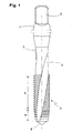
- a commonly used bottoming screw tap incorporates a shank 1 and a square 2, which is disposed on the shank 1 for the transmission of a turning moment in a case.
- the shank bears a taper-shaped neck 3 with a screw head 4.
- the head 4 and the neck 3 are provided with, for example, three equidistant, helical grooves for chips 5.
- the tool is normally provided with a conical tip 6, which has no function, but is there only on manufacturing grounds.
- the commonly used screw tap incorporates a chamfer a and a guide part b .
- the chamfer a tapers substantially uniformly to the front. Whereas the whole of the chipping takes place in the chamfer area a, the guide part b serves merely for the axial guiding of the tool in the already produced thread.
- a minimal lubricant tank is already located in the tool producing thread according to the invention, wherein the lubricant is conveyed via fine bores only with the aid of centrifugal force during the machining, without an additional external effect on the tool cutting edges. Moreover, no coolant is supplied from the outside during the whole period of use, the tank takes over this function.
- the screw head incorporates a minimal lubricant tank (reservoir) 7, which consists of a bore which issues on the distal end of the tool.
- the distal-end front part of the bore can be widened slightly and accommodate a closure 8.
- the conical tip 6 in Fig. 1 has preferably been removed.
- the nature of the closure 8 is not material to the invention.
- a bolt for example, can also be glued in or pressed in.
- a soft bolt of light metal such as aluminium is also conceivable, which is heat-sealed during the pressing in. Blind rivets are also possible.
- feed bores 9 Disposed obliquely or directly radially outwards from the tank 7 are feed bores 9 for feeding the lubricant to the chipping point, i.e. to the chamfer, and optionally also to the guide part.
- the necessary bore diameter of said feed bores depends on the viscosity of the minimal lubricant and lies in general in the range between 0.01 and 0.4 mm, preferably between 0.05 and 0.2 mm.
- the number of feed bores is not critical and can be e.g. from two to eight. Up to approximately 0.2 mm diameter the feed bores are normally manufactured by erosion; below 0.2 mm by laser drilling. Both methods can be used both for high-speed steel and for carbide metal.
- the required amount of minimal lubricant is extremely small and normally lies between 1 and 20 ml per hour.
- a minimal lubricant with particularly good SPRITE effect i.e. the property of the minimal lubricant to spread and distribute itself very rapidly on the surface of the tool and of the workpiece.
- the use of simply any cutting oil, such as were known previously, is therefore not involved, but special minimal lubricants, such as are already known today.
- the shank 1 can also be used as a minimal lubrication tank.
- the tank bore 71 is moreover continuous, from the distal end of the tool up to the shank end.
- the bore can have a greater diameter in the shank than in the front part, see bore part 11.
- the rear end of the tank bore can also be sealed by means of a closure (see closure 12), in the same way as the front end.
- the lubricant can be pressed to the front to the chipping point by means of a plunger 13 and a spring 14.
- the spring 14 is moreover located between the axially movable plunger 13 and the end closure 12'.
- the screw tapping can also be performed in difficult materials without the use of expensive minimal lubrication devices and without additional lubrication from outside.
- the lubricant comes out only when the tool rotates. Consequently only very small amounts are needed.
- Tests have shown that a lubricant volume of about 5 ml suffices for the whole life of a screw tap of the size M8 for the machining of heat treatable steel. The life of such a screw tap is about 90 minutes.
Landscapes
- Engineering & Computer Science (AREA)
- Mechanical Engineering (AREA)
- Drilling Tools (AREA)
- Cutting Tools, Boring Holders, And Turrets (AREA)
- Harvester Elements (AREA)
- Turning (AREA)
- Yarns And Mechanical Finishing Of Yarns Or Ropes (AREA)
Claims (6)
- Werkzeug zum Herstellen von Innengewinde, wie zum Beispiel ein Gewindebohrer oder Gewindeformer, wobei das Werkzeug als Merkmal Innenbohrungen aufweist, welche Schmiermittel von einer Mittelbohrung zum Umfang des Werkzeugs führen, dadurch gekennzeichnet, daß die Mittelbohrung in der Form eines Schmiermitteltanks (7, 7') ist und der Tank in dem Werkzeug eingeschlossen ist und das Volumen des Tanks derart ist, daß es ausreichend Schmiermittel für die ganze Lebensdauer des Werkzeugs (3) unterbringt und daß das Schmiermittel über feine Zuführbohrungen (9) zu der das Gewinde herstellenden äußeren Fläche des Werkzeugs geführt wird.
- Werkzeug nach Anspruch 1, bei welchem der Schmiermitteltank ein sogenannter Minimalschmiermitteltank ist.
- Werkzeug nach Anspruch 1, bei welchem der Durchmesser der Zuführbohrungen zwischen 0,01 und 0,4 mm liegt.
- Werkzeug nach einem der vorhergehenden Ansprüche, bei welchem der. Schmiermitteltank durch eine mittige, axiale Bohrung in dem Werkzeug erzeugt wird, wobei er am vorderen, distalen Ende mittels eines Verschlusses (8) abgedichtet ist.
- Werkzeug nach Anspruch 4, bei welchem die vorgenannte Bohrung in dem Werkzeug durchgehend ist, wobei ein Verschluß (12) auch am rückwärtigen Ende (10) angeordnet ist.
- Werkzeug nach Anspruch 5, bei welchem das Schmiermittel mit Hilfe eines Kolbens (13) und einer Feder (14) zur Vorderseite gedrückt wird.
Applications Claiming Priority (3)
| Application Number | Priority Date | Filing Date | Title |
|---|---|---|---|
| SE9701333 | 1997-04-11 | ||
| SE9701333A SE512456C2 (sv) | 1997-04-11 | 1997-04-11 | Verktyg för framställning av invändiga gängor |
| PCT/SE1998/000623 WO1998046388A1 (en) | 1997-04-11 | 1998-04-03 | Tool producing internal thread |
Publications (2)
| Publication Number | Publication Date |
|---|---|
| EP0973627A1 EP0973627A1 (de) | 2000-01-26 |
| EP0973627B1 true EP0973627B1 (de) | 2002-09-25 |
Family
ID=20406523
Family Applications (1)
| Application Number | Title | Priority Date | Filing Date |
|---|---|---|---|
| EP98917850A Expired - Lifetime EP0973627B1 (de) | 1997-04-11 | 1998-04-03 | Werkzeug zum herstellen von innengewinde |
Country Status (7)
| Country | Link |
|---|---|
| US (1) | US5993120A (de) |
| EP (1) | EP0973627B1 (de) |
| JP (1) | JP3842300B2 (de) |
| AT (1) | ATE224787T1 (de) |
| DE (1) | DE69808261T2 (de) |
| SE (1) | SE512456C2 (de) |
| WO (1) | WO1998046388A1 (de) |
Families Citing this family (33)
| Publication number | Priority date | Publication date | Assignee | Title |
|---|---|---|---|---|
| US6116825A (en) * | 1995-08-08 | 2000-09-12 | Kennametal Hertel Ag Werkzeuge + Hartstoffe | Rotating cutting tool with a coolant passage and a method of providing it with coolant |
| MX245299B (en) * | 1998-02-27 | 2007-04-24 | Large tube assemblies for reverse osmosis | |
| IT1319307B1 (it) * | 2000-02-28 | 2003-10-10 | Pi Effe Ci Dei F Lli Vernasca | Utensile filettatore perfezionato |
| SE522664C2 (sv) * | 2001-04-30 | 2004-02-24 | Sandvik Ab | Skärande gängtapp och förfarande för dess tillverkning |
| SE519067C2 (sv) | 2001-05-22 | 2003-01-07 | Sandvik Ab | Gängtapp med lobformat tvärsnitt och gängslappningsparti |
| DE10142265B4 (de) * | 2001-08-29 | 2005-04-28 | Arno Friedrichs | Stabförmiges Werkzeug zur spanenden Bearbeitung eines Werkstücks |
| US6554550B2 (en) * | 2001-09-07 | 2003-04-29 | North American Tool Corporation | Tandem tap and method for cutting screw threads |
| DE10155979A1 (de) * | 2001-11-14 | 2003-05-22 | Sandvik Ab | Gewindeschneidwerkzeug |
| DE10246871A1 (de) * | 2002-10-08 | 2004-05-06 | Sandvik Ab | Gewindewerkzeug mit Kühlmittelzufuhr |
| SE527227C2 (sv) * | 2003-09-12 | 2006-01-24 | Seco Tools Ab | Verktyg för spånavskiljande bearbetning med en axiell cylindrisk kanal |
| US7144208B2 (en) * | 2004-06-07 | 2006-12-05 | Kennametal Inc. | Low torque tap |
| JP2006297577A (ja) * | 2005-04-25 | 2006-11-02 | Osg Corp | タップ及び埋め栓 |
| DE102008053772A1 (de) * | 2008-10-22 | 2010-04-29 | Komet Jel Precision Tools | Gewindeformer |
| DE112008004051T5 (de) * | 2008-10-27 | 2012-05-03 | Osg Corp. | Spiralgewindebohrer |
| DE102009000891B4 (de) * | 2009-02-16 | 2019-09-19 | Hilti Aktiengesellschaft | Verfahren und Gewindewerkzeug, jeweils zur Ausformung eines lnnengewindes an einem Grundkörper |
| DE102010054476B4 (de) * | 2010-12-14 | 2016-07-07 | Audi Ag | Verfahren zum Herstellen eines Gewindes in einem Werkstück |
| JP5731643B2 (ja) * | 2011-06-08 | 2015-06-10 | オーエスジー株式会社 | チップ着脱式回転工具 |
| CN104107963A (zh) * | 2013-04-19 | 2014-10-22 | 苏州文鼎模具有限公司 | 一种丝锥 |
| US20170239740A1 (en) * | 2014-09-23 | 2017-08-24 | Danske Vaerktoej Aps | Thread cutting tap |
| USD769684S1 (en) * | 2015-04-30 | 2016-10-25 | A & E Incorporated | Thread restorer tool |
| CN105014129B (zh) * | 2015-07-30 | 2017-11-17 | 杨仁卫 | 离心喷水钻头 |
| CN105108212B (zh) * | 2015-07-30 | 2017-11-17 | 杨仁卫 | 带喷水装置的钻头 |
| CN105171066B (zh) * | 2015-07-30 | 2017-11-17 | 杨仁卫 | 喷水钻头 |
| JP6722153B2 (ja) | 2017-07-28 | 2020-07-15 | 株式会社Subaru | ドリル、穿孔ユニット及び穿孔方法 |
| JP6311059B1 (ja) * | 2017-09-20 | 2018-04-11 | 株式会社芝技研 | 細いドリル |
| US10421135B2 (en) | 2017-11-03 | 2019-09-24 | Kennametal Inc. | Rotary cutting tool with coolant passages and method of making same |
| US10773323B2 (en) * | 2018-08-21 | 2020-09-15 | Ford Motor Company | Minimum quantity lubrication thread tap |
| JP7207983B2 (ja) * | 2018-12-10 | 2023-01-18 | 株式会社Subaru | ドリル、穿孔ユニット及び被穿孔品を製作する方法 |
| CN109570581A (zh) * | 2018-12-21 | 2019-04-05 | 阳江十八子刀剪制品有限公司 | 一种新型钛合金刀具 |
| JP7267766B2 (ja) | 2019-02-14 | 2023-05-02 | 株式会社Subaru | 回転切削工具、回転切削ユニット及び被切削加工品を製作する方法 |
| DE102019130009A1 (de) * | 2019-11-07 | 2021-05-12 | EMUGE-Werk Richard Glimpel GmbH & Co. KG Fabrik für Präzisionswerkzeuge | Werkzeug zur spanlosen Erzeugung oder Nachbearbeitung eines Gewindes, Verfahren zum Herstellen des Werkzeugs und Verfahren zum Herstellen eines Gewindes |
| JP7545789B2 (ja) | 2020-05-27 | 2024-09-05 | 株式会社Subaru | 孔の仕上げ加工工具及び孔の仕上げ加工品の製造方法 |
| CN112895167B (zh) * | 2021-03-16 | 2025-06-06 | 苏州锐霸工具有限公司 | 用于水钻的冷却机构 |
Family Cites Families (17)
| Publication number | Priority date | Publication date | Assignee | Title |
|---|---|---|---|---|
| US83371A (en) * | 1868-10-27 | Improved screw-tap | ||
| US3153885A (en) * | 1961-10-09 | 1964-10-27 | Chauncey A R Keller | Cyclindrical cutter device |
| DE2414635C3 (de) * | 1974-03-26 | 1980-06-26 | Prototyp-Werke Gmbh, 7615 Zell | Spanlos-Gewindeformer |
| SU642091A1 (ru) * | 1976-04-25 | 1979-01-15 | Челябинский Станкостроительный Завод Им.Серго Орджоникидзе | Способ соединени рабочей части инструмента с внутренними каналами с хвостовиком |
| FR2460172A1 (fr) * | 1979-07-04 | 1981-01-23 | Deltal Ste Nle | Outil coupant de revolution a lubrification interne |
| DE3037568C2 (de) * | 1980-10-04 | 1985-04-11 | Günther & Co, 6000 Frankfurt | Genuteter Gewindebohrer |
| JPS58102613A (ja) * | 1981-12-04 | 1983-06-18 | Inax Corp | 貯液体孔あけ器具 |
| DE3307555C2 (de) * | 1983-03-03 | 1985-07-11 | Gühring, Gottlieb, 7470 Albstadt | Bohrungs-Nachbearbeitungswerkzeug |
| DE8324835U1 (de) * | 1983-08-30 | 1983-12-08 | Wilhelm Fette Gmbh, 2053 Schwarzenbek | Gewindebohrer |
| DE3419850A1 (de) * | 1984-05-28 | 1985-11-28 | Süddeutsches Präzisionswerk GmbH & Co, 7340 Geislingen | Innengewinde-schneidwerkzeug |
| DE3569897D1 (en) * | 1985-09-16 | 1989-06-08 | Dihart Ag | Reamer with cooling provision |
| DE8623509U1 (de) * | 1986-09-02 | 1988-01-07 | Ernst Reime GmbH & Co KG Spezialfabrik für Präzisionsgewindeschneidwerkzeuge, 8500 Nürnberg | Sackloch-Gewindebohrer |
| JPH0763894B2 (ja) * | 1987-01-29 | 1995-07-12 | 株式会社不二越 | 油穴付きタップ |
| US4762444A (en) * | 1987-03-16 | 1988-08-09 | Mena Carl M | Screw tap with lubrication and extraction bores |
| JPH02100820A (ja) * | 1988-06-20 | 1990-04-12 | Nachi Fujikoshi Corp | 油穴付き転造タップ |
| JPH06500505A (ja) * | 1990-09-14 | 1994-01-20 | マーフィー、マーティン ジョン マイクル | ねじが形成された穴を有する要素 |
| SE505742C2 (sv) * | 1993-09-07 | 1997-10-06 | Sandvik Ab | Gängtapp |
-
1997
- 1997-04-11 SE SE9701333A patent/SE512456C2/sv not_active IP Right Cessation
-
1998
- 1998-04-03 WO PCT/SE1998/000623 patent/WO1998046388A1/en not_active Ceased
- 1998-04-03 JP JP54380198A patent/JP3842300B2/ja not_active Expired - Fee Related
- 1998-04-03 EP EP98917850A patent/EP0973627B1/de not_active Expired - Lifetime
- 1998-04-03 DE DE69808261T patent/DE69808261T2/de not_active Expired - Lifetime
- 1998-04-03 AT AT98917850T patent/ATE224787T1/de not_active IP Right Cessation
- 1998-04-13 US US09/058,851 patent/US5993120A/en not_active Expired - Fee Related
Also Published As
| Publication number | Publication date |
|---|---|
| DE69808261T2 (de) | 2003-05-28 |
| ATE224787T1 (de) | 2002-10-15 |
| WO1998046388A1 (en) | 1998-10-22 |
| DE69808261D1 (de) | 2002-10-31 |
| SE512456C2 (sv) | 2000-03-20 |
| US5993120A (en) | 1999-11-30 |
| JP3842300B2 (ja) | 2006-11-08 |
| EP0973627A1 (de) | 2000-01-26 |
| SE9701333L (sv) | 1998-10-12 |
| SE9701333D0 (sv) | 1997-04-11 |
| JP2001520587A (ja) | 2001-10-30 |
Similar Documents
| Publication | Publication Date | Title |
|---|---|---|
| EP0973627B1 (de) | Werkzeug zum herstellen von innengewinde | |
| CA1255888A (en) | Method and apparatus for machining | |
| EP1383623B2 (de) | Gewindebohrer und herstellungsverfahren dafür | |
| JP5694799B2 (ja) | シャフトツールおよび接続片を備えた装置 | |
| US7478978B2 (en) | Cutting tool and tool head | |
| US7320565B2 (en) | Edge-carrying drill, method for the manufacture of the drill, and drilling tool comprising such a drill | |
| AU663221B2 (en) | Toolholder assembly and method | |
| US7156589B2 (en) | Tool holder of machine tool | |
| US7073988B2 (en) | Threaded tool with coolant supply | |
| US5085540A (en) | Endmill with notched shank | |
| JP2894924B2 (ja) | 切削加工方法および装置 | |
| JPH10225814A (ja) | 切削加工方法 | |
| JP2005529755A (ja) | 内部および/または外部ばり取りのためのばり取り工具及びそれを用いたばり取り方法 | |
| WO1994017946A1 (en) | Thread tapping cutting tool | |
| US20050029423A1 (en) | Tool holder | |
| JP2511368B2 (ja) | ク―ラント供給方法および装置 | |
| JPH02100820A (ja) | 油穴付き転造タップ | |
| CN101282809B (zh) | 孔加工工具以及预钻孔的加工方法 | |
| JPH10100020A (ja) | ドリル付タップ | |
| JP4516169B2 (ja) | 複合加工工具 | |
| JP2011051070A (ja) | オイルホール付きタップ、およびオイルホール閉塞方法 | |
| JPH0512023U (ja) | 穴明け工具及びその取付け構造 | |
| KR200336986Y1 (ko) | 스로우어웨이 드릴 | |
| GB2441438A (en) | Tool holder for a turret lathe | |
| JP2006297577A (ja) | タップ及び埋め栓 |
Legal Events
| Date | Code | Title | Description |
|---|---|---|---|
| PUAI | Public reference made under article 153(3) epc to a published international application that has entered the european phase |
Free format text: ORIGINAL CODE: 0009012 |
|
| 17P | Request for examination filed |
Effective date: 19990902 |
|
| AK | Designated contracting states |
Kind code of ref document: A1 Designated state(s): AT CH DE ES FR GB IT LI SE |
|
| 17Q | First examination report despatched |
Effective date: 20010702 |
|
| GRAG | Despatch of communication of intention to grant |
Free format text: ORIGINAL CODE: EPIDOS AGRA |
|
| GRAG | Despatch of communication of intention to grant |
Free format text: ORIGINAL CODE: EPIDOS AGRA |
|
| GRAH | Despatch of communication of intention to grant a patent |
Free format text: ORIGINAL CODE: EPIDOS IGRA |
|
| GRAH | Despatch of communication of intention to grant a patent |
Free format text: ORIGINAL CODE: EPIDOS IGRA |
|
| GRAA | (expected) grant |
Free format text: ORIGINAL CODE: 0009210 |
|
| AK | Designated contracting states |
Kind code of ref document: B1 Designated state(s): AT CH DE ES FR GB IT LI SE |
|
| PG25 | Lapsed in a contracting state [announced via postgrant information from national office to epo] |
Ref country code: LI Free format text: LAPSE BECAUSE OF FAILURE TO SUBMIT A TRANSLATION OF THE DESCRIPTION OR TO PAY THE FEE WITHIN THE PRESCRIBED TIME-LIMIT Effective date: 20020925 Ref country code: CH Free format text: LAPSE BECAUSE OF FAILURE TO SUBMIT A TRANSLATION OF THE DESCRIPTION OR TO PAY THE FEE WITHIN THE PRESCRIBED TIME-LIMIT Effective date: 20020925 Ref country code: AT Free format text: LAPSE BECAUSE OF FAILURE TO SUBMIT A TRANSLATION OF THE DESCRIPTION OR TO PAY THE FEE WITHIN THE PRESCRIBED TIME-LIMIT Effective date: 20020925 |
|
| REF | Corresponds to: |
Ref document number: 224787 Country of ref document: AT Date of ref document: 20021015 Kind code of ref document: T |
|
| REG | Reference to a national code |
Ref country code: GB Ref legal event code: FG4D |
|
| REG | Reference to a national code |
Ref country code: CH Ref legal event code: EP |
|
| REF | Corresponds to: |
Ref document number: 69808261 Country of ref document: DE Date of ref document: 20021031 |
|
| PG25 | Lapsed in a contracting state [announced via postgrant information from national office to epo] |
Ref country code: SE Free format text: LAPSE BECAUSE OF FAILURE TO SUBMIT A TRANSLATION OF THE DESCRIPTION OR TO PAY THE FEE WITHIN THE PRESCRIBED TIME-LIMIT Effective date: 20021225 |
|
| PG25 | Lapsed in a contracting state [announced via postgrant information from national office to epo] |
Ref country code: ES Free format text: LAPSE BECAUSE OF FAILURE TO SUBMIT A TRANSLATION OF THE DESCRIPTION OR TO PAY THE FEE WITHIN THE PRESCRIBED TIME-LIMIT Effective date: 20030328 |
|
| ET | Fr: translation filed | ||
| REG | Reference to a national code |
Ref country code: CH Ref legal event code: PL |
|
| PLBE | No opposition filed within time limit |
Free format text: ORIGINAL CODE: 0009261 |
|
| STAA | Information on the status of an ep patent application or granted ep patent |
Free format text: STATUS: NO OPPOSITION FILED WITHIN TIME LIMIT |
|
| 26N | No opposition filed |
Effective date: 20030626 |
|
| REG | Reference to a national code |
Ref country code: GB Ref legal event code: 732E |
|
| REG | Reference to a national code |
Ref country code: GB Ref legal event code: 732E |
|
| REG | Reference to a national code |
Ref country code: FR Ref legal event code: TP |
|
| REG | Reference to a national code |
Ref country code: FR Ref legal event code: TP |
|
| PGFP | Annual fee paid to national office [announced via postgrant information from national office to epo] |
Ref country code: GB Payment date: 20100325 Year of fee payment: 13 |
|
| PGFP | Annual fee paid to national office [announced via postgrant information from national office to epo] |
Ref country code: FR Payment date: 20100521 Year of fee payment: 13 |
|
| PGFP | Annual fee paid to national office [announced via postgrant information from national office to epo] |
Ref country code: IT Payment date: 20100417 Year of fee payment: 13 Ref country code: DE Payment date: 20100430 Year of fee payment: 13 |
|
| REG | Reference to a national code |
Ref country code: DE Ref legal event code: R119 Ref document number: 69808261 Country of ref document: DE |
|
| REG | Reference to a national code |
Ref country code: DE Ref legal event code: R119 Ref document number: 69808261 Country of ref document: DE |
|
| GBPC | Gb: european patent ceased through non-payment of renewal fee |
Effective date: 20110403 |
|
| REG | Reference to a national code |
Ref country code: FR Ref legal event code: ST Effective date: 20111230 |
|
| PG25 | Lapsed in a contracting state [announced via postgrant information from national office to epo] |
Ref country code: FR Free format text: LAPSE BECAUSE OF NON-PAYMENT OF DUE FEES Effective date: 20110502 |
|
| PG25 | Lapsed in a contracting state [announced via postgrant information from national office to epo] |
Ref country code: GB Free format text: LAPSE BECAUSE OF NON-PAYMENT OF DUE FEES Effective date: 20110403 Ref country code: IT Free format text: LAPSE BECAUSE OF NON-PAYMENT OF DUE FEES Effective date: 20110403 |
|
| PG25 | Lapsed in a contracting state [announced via postgrant information from national office to epo] |
Ref country code: DE Free format text: LAPSE BECAUSE OF NON-PAYMENT OF DUE FEES Effective date: 20111031 |