EP0973655B1 - Mécanisme de déblocage à manche de commande unique destiné à être utilisé avec un siège de véhicule - Google Patents
Mécanisme de déblocage à manche de commande unique destiné à être utilisé avec un siège de véhicule Download PDFInfo
- Publication number
- EP0973655B1 EP0973655B1 EP98914757A EP98914757A EP0973655B1 EP 0973655 B1 EP0973655 B1 EP 0973655B1 EP 98914757 A EP98914757 A EP 98914757A EP 98914757 A EP98914757 A EP 98914757A EP 0973655 B1 EP0973655 B1 EP 0973655B1
- Authority
- EP
- European Patent Office
- Prior art keywords
- latch means
- secondary latch
- vehicle seat
- pivot axis
- plate
- Prior art date
- Legal status (The legal status is an assumption and is not a legal conclusion. Google has not performed a legal analysis and makes no representation as to the accuracy of the status listed.)
- Expired - Lifetime
Links
- 230000007246 mechanism Effects 0.000 title claims description 62
- 230000000694 effects Effects 0.000 claims description 17
- 239000007787 solid Substances 0.000 description 7
- 238000004519 manufacturing process Methods 0.000 description 2
- 238000000034 method Methods 0.000 description 2
- 230000000717 retained effect Effects 0.000 description 2
- 230000008520 organization Effects 0.000 description 1
Images








Classifications
-
- B—PERFORMING OPERATIONS; TRANSPORTING
- B60—VEHICLES IN GENERAL
- B60N—SEATS SPECIALLY ADAPTED FOR VEHICLES; VEHICLE PASSENGER ACCOMMODATION NOT OTHERWISE PROVIDED FOR
- B60N2/00—Seats specially adapted for vehicles; Arrangement or mounting of seats in vehicles
- B60N2/24—Seats specially adapted for vehicles; Arrangement or mounting of seats in vehicles for particular purposes or particular vehicles
- B60N2/32—Seats specially adapted for vehicles; Arrangement or mounting of seats in vehicles for particular purposes or particular vehicles convertible for other use
- B60N2/36—Seats specially adapted for vehicles; Arrangement or mounting of seats in vehicles for particular purposes or particular vehicles convertible for other use into a loading platform
- B60N2/366—Seats specially adapted for vehicles; Arrangement or mounting of seats in vehicles for particular purposes or particular vehicles convertible for other use into a loading platform characterised by the locking device
-
- B—PERFORMING OPERATIONS; TRANSPORTING
- B60—VEHICLES IN GENERAL
- B60N—SEATS SPECIALLY ADAPTED FOR VEHICLES; VEHICLE PASSENGER ACCOMMODATION NOT OTHERWISE PROVIDED FOR
- B60N2/00—Seats specially adapted for vehicles; Arrangement or mounting of seats in vehicles
- B60N2/02—Seats specially adapted for vehicles; Arrangement or mounting of seats in vehicles the seat or part thereof being movable, e.g. adjustable
- B60N2/20—Seats specially adapted for vehicles; Arrangement or mounting of seats in vehicles the seat or part thereof being movable, e.g. adjustable the back-rest being tiltable, e.g. to permit easy access
-
- B—PERFORMING OPERATIONS; TRANSPORTING
- B60—VEHICLES IN GENERAL
- B60N—SEATS SPECIALLY ADAPTED FOR VEHICLES; VEHICLE PASSENGER ACCOMMODATION NOT OTHERWISE PROVIDED FOR
- B60N2/00—Seats specially adapted for vehicles; Arrangement or mounting of seats in vehicles
- B60N2/02—Seats specially adapted for vehicles; Arrangement or mounting of seats in vehicles the seat or part thereof being movable, e.g. adjustable
- B60N2/20—Seats specially adapted for vehicles; Arrangement or mounting of seats in vehicles the seat or part thereof being movable, e.g. adjustable the back-rest being tiltable, e.g. to permit easy access
- B60N2/206—Seats specially adapted for vehicles; Arrangement or mounting of seats in vehicles the seat or part thereof being movable, e.g. adjustable the back-rest being tiltable, e.g. to permit easy access to a position in which it can be used as a support for objects, e.g. as a tray
-
- B—PERFORMING OPERATIONS; TRANSPORTING
- B60—VEHICLES IN GENERAL
- B60N—SEATS SPECIALLY ADAPTED FOR VEHICLES; VEHICLE PASSENGER ACCOMMODATION NOT OTHERWISE PROVIDED FOR
- B60N2/00—Seats specially adapted for vehicles; Arrangement or mounting of seats in vehicles
- B60N2/02—Seats specially adapted for vehicles; Arrangement or mounting of seats in vehicles the seat or part thereof being movable, e.g. adjustable
- B60N2/22—Seats specially adapted for vehicles; Arrangement or mounting of seats in vehicles the seat or part thereof being movable, e.g. adjustable the back-rest being adjustable
Definitions
- the present invention relates to release mechanisms for use with vehicle seat hinges having two pivot axes to permit a seatback to recline and to forwardly fold to a horizontal forwardly dumped position, and more particularly to single control handle release mechanisms for use with such vehicle seat hinges.
- Passenger vehicles especially combined passenger and utility type vehicles, commonly have front and rear seats that both recline and fold forwardly to a substantially horizontally disposed forwardly dumped position, as selected by a user, in order to accommodate increasing demand for more functional vehicle interiors. Placing a vehicle seat in its forwardly folded dumped position allows for carrying of large or lengthy objects inside the vehicle and provides a convenient substantially horizontal flat surface for articles that might be used in a vehicle, such as briefcases, laptop computers, and also food and drinks.
- Such vehicle seats typically include a pair of vehicle seat hinges, with each hinge having a mounting plate securely attached to a vehicle seat cushion.
- a sector plate associated with the seatback is pivotally mounted on the mounting plate for pivotal movement about a lower pivot axis.
- a rotational control plate is pivotally mounted on the sector plate for pivotal movement about an upper pivot axis and is securely attached to a vehicle seatback.
- the seatback is selectively pivotally movable about the lower pivot axis between a plurality of angular positions, typically including a plurality of reclining positions and also a plurality of partially forwardly (of vertical) inclined positions.
- the seatback is also forwardly foldable about the upper pivot axis between a design position and a forwardly dumped position, whereat the rear surface of the seatback is substantially horizontally disposed.
- one or more manually manipulable handle release mechanisms are used.
- a single control handle release mechanism for use with a vehicle seat hinge having a mounting plate securely attachable to a vehicle seat cushion means, a sector plate pivotally mounted on the mounting plate for selective pivotal movement about a first lower pivot axis, and a rotational control plate pivotally mounted on the sector plate for selective pivotal movement about a second upper pivot axis and securely attachable to a vehicle seatback means.
- the vehicle seatback means is pivotally movable with respect to the vehicle seat cushion means about the first lower pivot axis between a plurality of angular positions and forwardly foldable with respect to the vehicle seat cushion means about the second upper pivot axis between a design position and a forwardly dumped position.
- the single control handle release mechanism comprises a primary latch means operatively interconnected between the mounting plate and the sector plate so as to be selectively movable between a latched configuration whereat the mounting plate and the sector plate are pivotally fixed one with respect to the other, and an unlatched configuration whereat the mounting plate and the sector plate are free to pivot about the first lower pivot axis such that the vehicle seatback means is pivotally movable, as aforesaid, between the plurality of angular positions.
- a secondary latch means is operatively interconnected between the sector plate and the rotational control plate so as to be selectively movable between a latched configuration whereat the sector plate and the rotational control plate are pivotally fixed one with respect to the other, and an unlatched configuration whereat the sector plate and the rotational control plate are free to forwardly fold, as aforesaid, between the design position and the forwardly dumped position.
- a manually grippable handle means is rotatably mounted on the seat cushion means and operatively connected to the primary latch means, for movement from an initial position, corresponding to the latched configuration of the primary latch means and the latched configuration of the secondary latch means, to a first release position, at which first release position the manually grippable handle means effects the unlatched configuration of the primary latch means, thereby permitting pivotal folding, as aforesaid, of the vehicle seatback means about the first lower pivot axis between the plurality of angular positions.
- a link arm means is operatively interconnected between the secondary latch means and the vehicle seat cushion means for movement of the secondary latch means from the latched configuration to the unlatched configuration upon relative movement of the link arm means and the secondary latch means with respect to each other beyond a threshold position, thereby to release the vehicle seatback means to be forwardly foldable over the vehicle seat cushion means about the second upper pivot axis, as aforesaid.
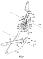
- the single control handle release mechanism 20 is for use with a vehicle seat hinge, as indicated by the general reference numeral 22, installed in a vehicle seat, as indicated by the general reference numeral 24.
- the vehicle seat hinge 22 has a mounting plate 30 securely attachable to a vehicle seat cushion means 26 (shown in dashed lining) by conventional fastening means (not shown), as is well known in the art.
- a sector plate 40 is pivotally mounted on the mounting plate 30, by means of a pin member 36, for selective pivotal movement about a first lower pivot axis "A".
- a rotational control plate 50 is pivotally mounted on the sector plate 40 by a pin member 42 and is retained in place by a mounting bracket 44, for selective pivotal movement about a second upper pivot axis "B" as limited by a sectoral slot 52 in the rotational control plate 50 engaged by a stop pin 46 securely mounted on the sector plate 40.
- the rotational control plate 50 is securely attachable to a vehicle seatback means 28 (shown in dashed lining) by conventional fastening means (not shown), as is well known in the art.
- the vehicle seatback means 28 is pivotally movable with respect to the vehicle seat cushion means 26 about the first lower pivot axis "A" between a plurality of angular positions, including return forwardly folding movement, as indicated by double ended arrow "C” in Figure 3, or return reclining movement, as indicated by double ended arrow “D” in Figure 3.
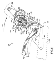
- angular positions include a substantially upright occupiable position, as can be best seen in Figures 3 and 4, various reclined positions, one of which reclined positions is shown in Figure 5, and also include partially forwardly angled positions, as can be best seen in Figures 6 and 7.
- the reclined positions and the partially forwardly angled positions are limited by a stop pin 47 securely mounted on the sector plate 40 so as to engage a sectoral slot 39 in the mounting plate 30.
- the vehicle seatback means 28 is also forwardly foldable with respect to the vehicle seat cushion means 26 about the second upper pivot axis "B" between a design position, as can be best seen in Figures 3 and 4, and a forwardly dumped position, as can be best seen in Figure 8.
- the single control handle release mechanism 20 comprises a primary latch means, as indicated by the reference numeral 60, operatively interconnected between the mounting plate 30 and the sector plate 40 and actuated by a manually grippable handle means 80.
- the primary latch means 60 comprises a known reclining adjustment mechanism that has a cam (not shown) rotatable by manipulation of the handle means 80. The cam effects radially inward and outward movement of a plurality of toothed latching pawls (not shown) within the primary latching means 60 and associated with the seat cushion means 26 into engagement and out of engagement with a co-operating annular ring gear (not shown) also within the primary latching means 60 and associated with the seatback means 28. Examples of modern versions of such a primary latch means 60 can be found in United States Patent No. 5,524,970 (Kienke et al ) and European Patent No. 808,742 (Rohee).
- the primary latch means 60 is selectively movable between a latched configuration and an unlatched configuration.
- the mounting plate 30 and the sector plate 40 are pivotally fixed one with respect to the other, and the seatback means 28 is precluded from pivotal movement about the first lower pivot axis "A", as aforesaid.
- the mounting plate 30 and the sector plate 40 are free to pivot about the first lower pivot axis "A" such that the vehicle seatback means 28 is pivotally movable, as aforesaid, between the plurality of angular positions, as can be best seen in Figures 3, 4, 5, 6, and 7.
- a secondary latch means designated by the general reference numeral 70 is operatively interconnected between the sector plate 40 and the rotational control plate 50 so as to be selectively movable between a latched configuration, as can be best seen in Figures 1 through 6, and an unlatched configuration, as can be best seen in Figures 7 through 8.
- the secondary latch means 70 is in the latched configuration, the sector plate 40 and the rotational control plate 50 are pivotally fixed one with respect to the other.
- the sector plate 40 and the rotational control plate 50 are free to forwardly fold about the second upper pivot axis "B", as aforesaid, between the design position, as can be best seen in Figures 1 through 6, and the forwardly dumped position, as can be best seen in Figure 8.
- the secondary latch means 70 essentially comprises a cam member 72 rotatably mounted on the sector plate 40 by a pin member 74, and retained in place by the mounting bracket 44, for pivotal movement between a latched configuration, as can be best seen in Figures 1 through 6, and especially Figure 6A, and an unlatched configuration, as can be best seen in Figures 7 and 8, and especially Figure 7A.
- the cam member 72 is spring biased toward its latched configuration by a spring member 76 having a first end 76a mounted on a lug 45 formed on the mounting bracket 44 and a second end 76b mounted on a post 78 projecting outwardly from the cam member 72.
- the pivotal movement of the cam member 72 is limited by a sectoral slot 53 in the rotational control plate 50 engaged by a stop pin 79 securely mounted on the cam member 72.
- the latched configuration of the cam member 72 corresponds to the latched configuration of the secondary latch means 70 and the unlatched configuration corresponds to the unlatched configuration of the secondary latch means 70.
- a camming surface 71 on the cam member 72 latchingly engages a co-operating cam receiving surface 54 on the rotational control plate 50.
- the camming surface 71 is removed from being latchingly engaged with the cam receiving surface 54.
- the secondary latch means 70 further comprises means for releasably locking the vehicle seatback means 28 in the forwardly dumped position shown in Figure 8.
- the means for releasably locking the vehicle seatback means 28 in the forwardly dumped position comprises a notch 56 disposed in the rotational control plate 50 and a projecting tooth member 77 disposed on the cam member 72 for co-operative interlocking with the notch 56 when the vehicle seatback means 28 is in the forwardly dumped position.
- the co-operating profiles of the notch 56 and the tooth member 77 are shaped such that lifting of the seatback means 28 with only slightly more than a minimal force in a rotational direction opposite to that of arrow "K" in Figure 8, causes unlocking of the notch 56 and the tooth member 77 with respect to each other, thus permitting the seatback to be pivoted about the second upper pivot axis "B", in the same rotational direction, so as to be returned from its forwardly folded position to its design position, as can be best seen in Figure 6.
- the manually grippable handle means 80 is mounted on the seat cushion means 26 via the pin member 36 so as to cause rotation of the pin member 26 upon rotation of the handle means 80. Such rotation of the pin member 36 causes selective latching and unlatching of the primary latch means 60, as is generally known in the art.
- the manually grippable handle means 80 is mounted for rotatable movement with the pin member, as indicated by arrows "E", “F”, and “G” in Figures 3, 4, and 5, respectively, from an initial position, as is shown in solid lining in Figures 3, 4, and 8, and as is shown in dashed lining in Figure 5, to a first release position, as is shown in solid lining in Figures 5 through 7, and as is shown in dashed lining in Figure 8.
- the manually grippable handle means 80 is thus used to selectively move the primary latch means 60 from the latched configuration to the unlatched configuration, thus permitting reclining of the vehicle seatback means 28, as indicated by arrow "H” in Figure 5, or to permit initial forward folding of the vehicle seatback means 28, as indicated by arrows "I” and “J” in Figures 6 and 7, respectively.
- the manually grippable handle means 80 is preferably spring biased towards its initial position by internal springs (not shown) positioned within the primary latch means 60.
- the manually grippable handle means 80 is operatively connected to the primary latch means 60 via the pin member 36.
- a slave cable (not shown) may be interconnected between the manually grippable handle means 80 and a primary latch means (not shown) on a second vehicle seat hinge (not shown) associated with the opposite other side vehicle seat 24, so as to translate motion of the handle means 80 to such other primary latch means (not shown).
- Such use of a slave cable mechanism to translate actuatory motion to a second vehicle seat hinge means is well known in the art.
- the first release position of the manually grippable handle means 80 corresponds to the latched configuration of the primary latch means 60 and the latched configuration of the secondary latch means 70.
- the manually grippable handle means 80 effects the unlatched configuration of the primary latch means 60, thereby permitting pivotal folding, as aforesaid, of the vehicle seatback means 28 about the first lower pivot axis "A" between the plurality of angular positions.
- An elongate link arm means 90 is operatively interconnected between the secondary latch means 70 and the vehicle seat cushion means 26.
- the link arm means 90 has a first end 91 pivotally connected to the vehicle seat cushion means 26 by means of a mounting pin 35 secured to the mounting plate 30, as can be sen in Figures 3, 5, 6, 7, and 8, and as can be best seen in Figure 4.
- the second end 92 of the link arm means 90 further comprises an elongated slot 94 having a proximal end 94a disposed toward the first end 91 of the link arm means 90 and a distal end 94b disposed toward the second end 92 of the link arm means 90.
- the second end 92 of the link arm means 90 is operatively connected to the secondary latch means 70 by means of the pin member 79 mounted on the cam member 72, which pin member 79 engages the elongated slot 94 in lost-motion sliding relation to effect the operative connection between the link arm means 90 and the secondary latch means 70.
- the elongated slot 94 is positioned and dimensioned such that at the threshold position of the link arm means 90 and the secondary latch means 70, as is illustrated in Figures 6 and 6A, the pin member 79 is disposed at the distal end 94b of the elongated slot 94 in load bearing relationship to effect the movement of the secondary latch means 70 to the unlatched configuration as shown in Figure 7.
- the elongate link arm means 90 is operatively interconnected between the secondary latch means 70 and the vehicle seat cushion means 26 as described, for movement of the secondary latch means 70 from the latched configuration to the unlatched configuration upon relative movement of the link arm means 90 and the pin member 79 of the secondary latch means 70 with respect to each other beyond the threshold position illustrated in Figure 6.
- the relative movement of the link arm means 90 and the secondary latch means 70 with respect to each other occurs upon forwardly folded pivotal movement of the vehicle seatback means 28 about the first lower pivot axis "A" following the movement of the handle means 80 to the first released position.
- the vehicle seatback means 28 is released so as to be forwardly foldable over the vehicle seat cushion means 26 about the second upper pivot axis "B", as aforesaid, to a forwardly dumped position, as can be best seen in Figure 8.
- the handle means 80 In use, in order to position the vehicle seatback means 28 in its forwardly dumped position, as can be best seen in Figure 8, the handle means 80 is rotated from an initial position, as can be best seen in Figures 3 and 4, by being manually lifted, as indicated by arrows "E” and “F", to the first release position, as can be best seen in Figures 6 and 7, to thereby unlatch the primary latch means 60.
- the vehicle seatback means 28 is then initially folded forwardly by hand to the position shown in Figure 6, as indicated by arrow "I".
- the pin member 79 engages the elongated slot 94 in lost-motion sliding relation until it reaches the threshold position, as described above, and as can be best seen in Figures 6 and 6A.
- the vehicle seatback means 28 is then folded forwardly even more by the user to the position shown in Figure 7, as indicated by arrow "J", to effect the operative connection between the link arm means 90 and the secondary latch means 70, thus unlatching the secondary latch means 70.
- the vehicle seatback means 28 may then be further forwardly folded, as indicated by arrow "K” in Figure 8, to the substantially horizontal forwardly dumped position, as defined by the stop pin 46 engaged in the sectoral slot 52.
- the vehicle seatback means 28 is locked in the substantially horizontal forwardly dumped position by means of co-operative interlocking of the projecting tooth member 77 with the notch 56.
- the handle means 80 is then released and returns under the influence of the previously mentioned internal spring biasing (not shown) of the primary latch means 60 to its initial position, as indicated by arrow "L" in Figure 8.
- the vehicle seatback means 28 may be released from being locked in the forwardly dumped position by mere lifting by the use of the seatback means 28 with only slightly more than a minimal force, as discussed above, due to the co-operating profiles of the notch 56 and the tooth member 77.
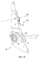
- FIG. 20 a second embodiment of the single control handle release mechanism of the present invention, as indicated by the general reference numeral 20'.
- the second embodiment single control handle release mechanism 20' is structurally and functionally similar to the first preferred embodiment single control handle release mechanism 20, except for the specific interconnection and operation of the link arm means 90'.
- the first end 91' of the link arm means 90' is pivotally connected to the vehicle seat cushion means 26 by means of a mounting pin 35 secured to the mounting plate 30, forwardly of the first lower pivot axis "A".
- the second end 92' of the link arm means 90' is operatively connected to the pin member 79 mounted on the cam member 72', which pin member 79 engages the elongated slot 94' in lost-motion sliding relation to effect the operative connection between the link arm means 90' and the secondary latch means 70.
- the elongated slot 94' is positioned and dimensioned such that, at the threshold position of the link arm means 90' and the secondary latch means 70, as is illustrated in Figures 11 and 11A, the pin member 79 is disposed at the proximal end 94a' of the elongated slot 94 in load bearing relationship to effect the movement of the secondary latch means 70 to the unlatched configuration upon continued forward folding of the vehicle seatback means 28.
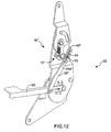
- FIG. 20'' there is shown a third embodiment of the single control handle release mechanism of the present invention, as indicated by the general reference numeral 20''.
- the third embodiment single control handle release mechanism 20'' is structurally and functionally similar to the second preferred embodiment single control handle release mechanism 20', except for the specific interconnection and operation of the link arm means 90''.
- the first end 91'' of the link arm means 90'' is pivotally connected to the vehicle seat cushion means 26 via the manually grippable handle means 80, by means of a mounting pin 35 secured to the handle means 80, such that the link arm means 90'' moves in concert with movement of the manually grippable handle means 80.
- the second end 92'' of the link arm means 90'' is operatively connected to the pin member 79 mounted on the cam member 72', which pin member 79 engages the elongated slot 94'' in lost-motion sliding relation to effect the operative connection between the link arm means 90'' and the secondary latch means 70''.
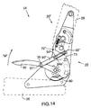
- the manually grippable handle means 80 is mounted for rotatable movement, as indicated by arrow "M", and "N" in Figures 14, and 15, respectively, from an initial position, as is shown in solid lining in Figure 14 and as is shown in dashed lining in Figure 15, to a first release position, as is shown in solid lining in Figures 15 and as is shown in dashed lining in Figure 16.
- the manually grippable handle means 80 is (as previously described) used to selectively move the primary latch means 60 from the latched configuration to the unlatched configuration, thus permitting reclining of the vehicle seatback means 28, as indicated by arrow "H” in Figure 15, to a reclined position as shown, or to permit initial forward folding of the vehicle seatback means 28, as indicated by arrow "P" in Figure 16.
- the manually grippable handle means 80 is further movable, as indicated by arrow "Q", from the first release position, as shown in dashed outline, through a threshold handle position, as shown in solid lining, whereat the means 80 to the threshold position of the link arm means 90" has been carried by movement of the handle means 80 to the threshold position of the link arm means 90" and the secondary latch means 70".
- the pin member 79 is disposed at the proximal end 94a" of the elongated slot 94" in load bearing relationship to effect the movement of the secondary latch means 70" to the unlatched configuration.
- the manually grippable handle means 80 is still further movable, as indicated by arrow "R" in Figure 17, to a second release position, as is shown in solid lining in Figure 17, to a second release position, as is shown in solid lining in Figure 17, beyond the threshold position of the link arm means 90" and the secondary latch means 70", so as to effect the movement of the secondary latch means 70" to the unlatched configuration, as aforesaid.
Landscapes
- Engineering & Computer Science (AREA)
- Aviation & Aerospace Engineering (AREA)
- Transportation (AREA)
- Mechanical Engineering (AREA)
- Seats For Vehicles (AREA)
- Chairs For Special Purposes, Such As Reclining Chairs (AREA)
Claims (11)
- Mécanisme de libération à poignée de commande unique destiné à être utilisé avec une charnière (22) dans un siège de véhicule, comprenant une plaque de montage (30) susceptible d'être attachée de manière assurée sur un coussin de siège (26) du véhicule, une plaque en secteur (40) montée en pivotement sur ladite plaque de montage pour un mouvement de pivotement sélectif autour d'un premier axe de pivotement inférieur, et une plaque de commande de rotation (50) montée en pivotement sur ladite plaque en secteur (40) pour un mouvement de pivotement sélectif autour d'un deuxième axe de pivotement supérieur et susceptible d'être attachée de manière assurée sur un dossier de siège (28) du véhicule, dans lequel, lorsque ladite charnière (22) de siège de véhicule est installée dans un siège de véhicule, ledit dossier de siège (28) est mobile en pivotement par rapport audit coussin de siège (26) autour dudit premier axe de pivotement inférieur entre une pluralité de positions angulaires et susceptible d'être replié vers l'avant par rapport audit coussin de siège (26) autour dudit deuxième axe de pivotement supérieur entre une position de service et une position rangée vers l'avant, ledit mécanisme de libération à poignée de commande unique comprenant :des moyens de verrouillage primaires (60) fonctionnellement interconnectés entre ladite plaque de montage (30) et ladite plaque en secteur (40) de manière à être sélectivement mobiles entre une configuration verrouillée dans laquelle ladite plaque de montage (30) et ladite plaque en secteur (40) sont fixées en pivotement l'une par rapport à l'autre, et une configuration déverrouillée dans laquelle ladite plaque de montage (30) et ladite plaque en secteur (40) sont libres de pivoter autour dudit premier axe de pivotement inférieur, de telle manière que ledit dossier de siège (28) est mobile en pivotement, comme précédemment énoncé, entre ladite pluralité de positions angulaires ;des moyens de verrouillage secondaires (70) fonctionnellement interconnectés entre ladite plaque en secteur (40) et ladite plaque de commande de rotation (50) de manière à être sélectivement mobiles entre une configuration verrouillée dans laquelle ladite plaque en secteur (40) et ladite plaque de commande de rotation (50) sont fixées en pivotement l'une par rapport à l'autre, et une configuration déverrouillée dans laquelle ladite plaque en secteur (40) et ladite plaque de commande de rotation (50) sont·libres de se replier vers l'avant, comme précédemment énoncé, entre ladite position de fonctionnement et ladite position rangée vers l'avant ;des moyens formant poignée (80) susceptibles d'être saisis à la main et montés en rotation sur ledit coussin de siège (26) et fonctionnellement connectés auxdits moyens de verrouillage primaires (60) pour un mouvement depuis une position initiale, correspondant à ladite configuration verrouillée desdits moyens de verrouillage primaires (60) et ladite configuration verrouillée desdits moyens de verrouillage secondaires (70), jusqu'à une première position de libération à laquelle lesdits moyens formant poignée (80) susceptibles d'être saisis à la main effectuent ladite configuration déverrouillée desdits moyens de verrouillage primaires (60), permettant ainsi un repliement par pivotement, comme précédemment énoncé, dudit dossier de siège (28) de véhicule autour dudit premier axe de pivotement inférieur entre ladite pluralité de positions angulaires, caractérisé par :un bras de liaison allongé (30) ayant une première extrémité (91) montée en pivotement sur ledit coussin de siège (26) et une deuxième extrémité (92) fonctionnellement connectée auxdits moyens de verrouillage secondaires (70) pour un mouvement desdits moyens de verrouillage secondaires (70) depuis ladite configuration verrouillée jusqu'à ladite configuration déverrouillée lors d'un mouvement relatif dudit bras de liaison (90) et desdits moyens de verrouillage secondaires (70) l'un par rapport à l'autre au-delà d'une position de seuil, pour libérer ainsi ledit dossier de siège (28) et le replier vers l'avant sur le coussin de siège (26) autour dudit deuxième axe de pivotement supérieur, comme précédemment énoncé.
- Mécanisme de libération à poignée de commande unique destiné à être utilisé avec une charnière (22) de siège de véhicule comprenant une plaque de montage (30) susceptible d'être attachée de façon assurée sur un coussin de siège (26) de véhicule, une plaque en secteur (40) montée en pivotement sur ladite plaque de montage pour un mouvement de pivotement sélectif autour d'un premier axe de pivotement inférieur, et une plaque de commande de rotation (50) montée en pivotement sur ladite plaque en secteur (40) pour un mouvement de pivotement sélectif autour d'un deuxième axe de pivotement supérieur et susceptible d'être attachée de manière assurée sur un dossier de siège (28) du véhicule, dans lequel, lorsque ladite charnière de siège (22) est installée dans un siège de véhicule, ledit dossier de siège (28) est mobile en pivotement par rapport audit coussin de siège (26) autour dudit premier axe de pivotement inférieur entre une pluralité de positions angulaires et susceptible d'être replié vers l'avant par rapport audit coussin de siège (26) autour dudit deuxième axe de pivotement supérieur entre une position de service et une position rangée vers l'avant, ledit mécanisme de libération à poignée de commande unique comprenant :des moyens de verrouillage primaires (60) fonctionnellement interconnectés entre ladite plaque de montage (30) et ladite plaque en secteur (40) de manière à être mobiles sélectivement entre une configuration verrouillée dans laquelle ladite plaque de montage (30) et ladite plaque en secteur (40) sont fixées en pivotement l'une par rapport à l'autre, et une configuration déverrouillée dans laquelle ladite plaque de montage (30) et ladite plaque en secteur (40) sont libres de pivoter autour dudit premier axe de pivotement inférieur, de telle sorte que ledit dossier de siège (28) est mobile en pivotement, comme précédemment énoncé, entre ladite pluralité de positions angulaires ;des moyens de verrouillage secondaires (70) fonctionnellement interconnectés entre ladite plaque en secteur (40) et ladite plaque de commande de rotation (50) de manière à être mobiles sélectivement entre une configuration verrouillée dans laquelle ladite plaque en secteur (40) et ladite plaque de commande de rotation (50) sont fixées en pivotement l'une par rapport à l'autre, et une configuration déverrouillée dans laquelle ladite plaque en secteur (40) et ladite plaque de commande de rotation (50) sont libres de se replier vers l'avant, comme précédemment énoncé, entre ladite position de service et ladite position rangée vers l'avant ;des moyens formant poignée (40) susceptibles d'être saisis à la main, montés en rotation sur ledit coussin de siège (26) et fonctionnellement connectés auxdits moyens de verrouillage primaires (60) pour un mouvement depuis une position initiale, correspondant à ladite configuration verrouillée desdits moyens de verrouillage primaires (60) et ladite configuration verrouillée desdits moyens de verrouillage secondaires (70), jusqu'à une première position de libération à laquelle lesdits moyens formant poignée (80) susceptibles d'être saisis à la main effectuent ladite configuration déverrouillée desdits moyens de verrouillage primaires (60), permettant ainsi de replier par pivotement, comme précédemment énoncé, ledit dossier de siège (28) autour dudit premier axe de pivotement inférieur entre ladite pluralité de positions angulaires, caractérisé par :un bras de liaison allongé (30) ayant une première extrémité (91) montée en pivotement sur lesdits moyens formant poignée (80) susceptibles d'être saisis à la main pour un mouvement avec lesdits moyens formant poignée (80), et une deuxième extrémité (92) fonctionnellement connectée auxdits moyens de verrouillage secondaires (70) pour un mouvement desdits moyens de verrouillage secondaires (70) depuis ladite configuration verrouillée jusqu'à ladite configuration déverrouillée lors d'un mouvement relatif dudit bras de liaison (90) et desdits moyens de verrouillage secondaires (70) l'un par rapport à l'autre au-delà d'une position de seuil, pour libérer ainsi ledit dossier de siège (28) et le replier vers l'avant sur le coussin de siège (26) autour dudit deuxième axe de pivotement supérieur, comme précédemment énoncé, et dans lequel lesdits moyens formant poignée (80) susceptibles d'être saisis à la main sont en outre mobiles depuis ladite première position de libération en passant par une position de seuil de la poignée à laquelle ledit bras de liaison (90) a été transporté par lesdits moyens formant poignée (80) jusqu'à ladite position de seuil dudit bras de liaison (90) et desdits moyens de verrouillage secondaires (70) jusqu'à une deuxième position de libération au-delà de ladite position de seuil dudit bras de liaison (90) et desdits moyens de verrouillage secondaires (70), de manière à effectuer ledit mouvement desdits moyens de verrouillage secondaires (70) jusqu'à ladite configuration déverrouillée, comme précédemment énoncé.
- Mécanisme de libération à poignée de commande unique selon la revendication 1, dans lequel ladite première extrémité (91) du bras de liaison (90) est montée en pivotement comme précédemment énoncé sur la plaque de montage (30) et dans lequel ledit mouvement relatif dudit bras de liaison (90) et desdits moyens de verrouillage secondaires (70) l'un par rapport à l'autre se produit lors du mouvement de pivotement de repli vers l'avant dudit dossier de siège (28) autour dudit premier axe de pivotement inférieur à la suite dudit mouvement de la poignée (80) vers ladite première position de libération.
- Mécanisme de libération à poignée de commande unique selon l'une des revendications 2 et 3, dans lequel la deuxième extrémité (92) dudit bras de liaison (90) comprend en outre une fente allongée (94) ayant une extrémité proximale (94a) disposée vers ladite première extrémité (91) dudit bras de liaison (90) et une extrémité distale (94b) disposée vers ladite deuxième extrémité (92) dudit bras de liaison (90), et dans lequel lesdits moyens de verrouillage secondaires (70) incluent un élément en forme de goupille (70), lequel s'engage dans ladite fente allongée (94) sous une relation de coulissement à course morte pour réaliser ladite connexion fonctionnelle entre ledit bras de liaison (90) et lesdits moyens de verrouillage secondaires (70).
- Mécanisme de libération à poignée de commande unique selon la revendication 4, dans lequel ladite fente allongée (94) est positionnée et dimensionnée de telle manière que, à ladite position de seuil dudit bras de liaison (90) et desdits moyens de verrouillage secondaires (70), ledit élément de goupille (79) est disposé à ladite extrémité proximale (94a) de ladite fente allongée (94) dans une relation de transmission de charge pour effectuer ledit mouvement desdits moyens de verrouillage secondaires (70) vers ladite configuration déverrouillée.
- Mécanisme de libération à poignée de commande unique selon la revendication 4, dans lequel ladite fente allongée (94) est positionnée et dimensionnée de telle manière que, à ladite position de seuil dudit bras de liaison (90) et desdits moyens de verrouillage secondaires (70), ledit élément de goupille (79) est disposé à ladite extrémité distale (94b) de ladite fente allongée (94) dans une relation de transmission de charge pour effectuer ledit mouvement des moyens de verrouillage secondaires (70) vers ladite configuration déverrouillée.
- Mécanisme de libération à poignée de commande unique selon l'une ou l'autre des revendications 5 et 6, dans lequel lesdits moyens de verrouillage secondaires (70) comprennent essentiellement un élément formant came (72) ayant une surface de came, ledit élément de came (72) étant monté sur ladite plaque en secteur (49) pour un mouvement de pivotement entre une configuration verrouillée correspondant à ladite configuration verrouillée desdits moyens de verrouillage secondaires (70), à laquelle ladite surface de came engage en verrouillage une surface de réception de came sur ladite plaque de commande de rotation (50), et une configuration déverrouillée correspondant à ladite configuration déverrouillée desdits moyens de verrouillage secondaires (70), à laquelle ladite surface de came est dégagée de son engagement de verrouillage avec ladite surface de réception de came.
- Mécanisme de libération à poignée de commande unique selon la revendication 7, dans laquelle ledit élément de came (72) est chargé par un ressort en direction de sa configuration verrouillée.
- Mécanisme de libération à poignée de commande unique selon la revendication 8, dans lequel lesdits moyens de verrouillage primaires (60) comprennent un mécanisme d'ajustement d'inclinaison connu.
- Mécanisme de libération à poignée de commande unique selon la revendication 9, dans lequel lesdits moyens de verrouillage secondaires (70) comprennent en outre des moyens pour verrouiller de façon libérable ledit dossier de siège (28) dans ladite position rangée vers l'avant.
- Mécanisme de libération à poignée de commande unique selon la revendication 10, dans lequel lesdits moyens pour verrouiller de façon libérable ledit dossier de siège (20) dans ladite position rangée vers l'avant comprennent une encoche disposée dans ladite plaque de commande de rotation (50), et un élément en forme de dent en projection disposé sur ledit élément de came (72) pour un interverrouillage en coopération avec ladite encoche lorsque ledit dossier de siège est dans ladite position rangée vers l'avant.
Applications Claiming Priority (3)
| Application Number | Priority Date | Filing Date | Title |
|---|---|---|---|
| US4307197P | 1997-04-08 | 1997-04-08 | |
| US43071P | 1997-04-08 | ||
| PCT/CA1998/000332 WO1998045136A1 (fr) | 1997-04-08 | 1998-04-07 | Mecanisme de deblocage a manche de commande unique destine a etre utilise avec un siege de vehicule |
Publications (2)
| Publication Number | Publication Date |
|---|---|
| EP0973655A1 EP0973655A1 (fr) | 2000-01-26 |
| EP0973655B1 true EP0973655B1 (fr) | 2002-07-10 |
Family
ID=21925333
Family Applications (1)
| Application Number | Title | Priority Date | Filing Date |
|---|---|---|---|
| EP98914757A Expired - Lifetime EP0973655B1 (fr) | 1997-04-08 | 1998-04-07 | Mécanisme de déblocage à manche de commande unique destiné à être utilisé avec un siège de véhicule |
Country Status (10)
| Country | Link |
|---|---|
| US (1) | US6328381B1 (fr) |
| EP (1) | EP0973655B1 (fr) |
| JP (1) | JP3419790B2 (fr) |
| KR (1) | KR20010006144A (fr) |
| CN (1) | CN1252029A (fr) |
| AU (1) | AU6915698A (fr) |
| BR (1) | BR9808512A (fr) |
| CA (1) | CA2286048C (fr) |
| DE (1) | DE69806472T2 (fr) |
| WO (1) | WO1998045136A1 (fr) |
Families Citing this family (72)
| Publication number | Priority date | Publication date | Assignee | Title |
|---|---|---|---|---|
| FR2799420B1 (fr) * | 1999-10-08 | 2002-01-04 | Faure Bertrand Equipements Sa | Siege de vehicule |
| DE19953686C1 (de) * | 1999-11-09 | 2001-08-23 | Keiper Gmbh & Co | Beschlag für die Rückenlehne von Fahrzeugsitzen, insbesondere von Kraftfahrzeugen |
| FR2804386B1 (fr) * | 2000-02-02 | 2002-05-17 | Faure Bertrand Equipements Sa | Siege de vehicule comportant un dossier rabattable vers l'avant |
| GB2359014B (en) * | 2000-02-12 | 2003-10-15 | Johnson Controls Automotive Uk | Foldable Reclining Vehicle Seat with Dual Control Mechanism |
| US6454355B2 (en) * | 2000-03-08 | 2002-09-24 | Faurecia Automotive Seating Canada Limited | Latching mechanism for seat assembly |
| USH2129H1 (en) * | 2000-08-09 | 2005-11-01 | Intier Automotive Inc. | Disc recliner assembly with fold-flat latch link mechanism |
| EP1315637B1 (fr) * | 2000-09-08 | 2006-05-03 | Intier Automotive Inc. | Ensemble siege a appui-tete autoreglable |
| US6513875B1 (en) | 2000-11-03 | 2003-02-04 | Porter Engineered Systems | Fold-flat reclining mechanism for a vehicle seat |
| EP1343655A2 (fr) * | 2000-12-20 | 2003-09-17 | Intier Automotive Inc. | Commande externe d'un ensemble inclinable |
| FR2820696B1 (fr) * | 2001-02-15 | 2003-08-08 | Faurecia Sieges Automobile | Siege de vehicule dote d'un dossier rabattable |
| DE10116160A1 (de) * | 2001-03-31 | 2002-10-10 | Keiper Gmbh & Co | Beschlag für einen Fahrzeugsitz |
| US6511129B1 (en) * | 2001-06-05 | 2003-01-28 | Fisher Dynamics Corporation | Folding seat hinge assembly with lift and push handle activation |
| FR2825955B1 (fr) * | 2001-06-15 | 2005-10-14 | Faurecia Automotive Seating Ca | Mecanisme d'articulation de siege de vehicule ameliore |
| US7021716B2 (en) | 2001-07-06 | 2006-04-04 | Intier Automotive Inc. | Tip easy entry and fold flat recliner assembly |
| FR2828454B1 (fr) * | 2001-08-09 | 2003-10-31 | Faurecia Sieges Automobile | Siege rabattable pour vehicule |
| FR2840267B1 (fr) * | 2002-05-28 | 2004-08-20 | Faurecia Sieges Automobile | Siege de vehicule |
| KR100461102B1 (ko) * | 2002-08-08 | 2004-12-13 | 현대자동차주식회사 | 차량용 리어시트의 리클라이닝 장치 |
| US7255399B2 (en) | 2002-11-08 | 2007-08-14 | Johnson Controls Technology Company | Thin profile folding vehicle seat |
| KR20040043036A (ko) * | 2002-11-15 | 2004-05-22 | 현대자동차주식회사 | 폴드 앤 다이브 타입의 자동차 시트 연결장치 |
| KR100501671B1 (ko) * | 2002-11-20 | 2005-07-18 | 현대자동차주식회사 | 시트백 각도 조절장치 |
| US20040217638A1 (en) * | 2003-04-25 | 2004-11-04 | Johnson Controls Technology Company | Fold flat recliner mechanism |
| US6863347B2 (en) * | 2003-05-27 | 2005-03-08 | Lear Corporation | Pivotable seat assembly |
| CN100366928C (zh) * | 2003-10-10 | 2008-02-06 | 虹光精密工业(苏州)有限公司 | 自锁式铰链装置及使用其的多功能一体机 |
| JP4562377B2 (ja) * | 2003-11-21 | 2010-10-13 | 富士機工株式会社 | 車両用シートリクライニング装置 |
| WO2005113287A2 (fr) * | 2004-05-12 | 2005-12-01 | Mjd Innovations, L.L.C. | Structure de siege reglable a verrouillage |
| DE102004056507B3 (de) * | 2004-11-24 | 2005-11-10 | Faurecia Autositze Gmbh & Co. Kg | Fahrzeugsitz |
| US7090277B2 (en) * | 2004-12-16 | 2006-08-15 | Dura Global Technologies, Inc. | Gear drive and linkage for power operated seat assembly |
| FR2883232B1 (fr) * | 2005-03-15 | 2012-08-31 | Hammerstein Gmbh C Rob | Garniture d'articulation de dossier pour un siege de vehicule automobile rabattable vers l'avant |
| DE102005012841A1 (de) * | 2005-03-19 | 2006-09-21 | Daimlerchrysler Ag | Fahrzeugsitz |
| US7887134B2 (en) * | 2005-04-20 | 2011-02-15 | Johnson Controls Technology Company | Interlock for a seat recliner mechanism |
| US7503099B2 (en) * | 2005-10-25 | 2009-03-17 | Fisher Dynamics Corporation | Memory mechanism for an adjustment mechanism |
| JP4940637B2 (ja) * | 2005-11-16 | 2012-05-30 | アイシン精機株式会社 | 車両用シートリクライニング装置 |
| KR100601809B1 (ko) * | 2005-12-21 | 2006-07-19 | 주식회사 오스템 | 차량용 시트의 폴딩 리클라이너 |
| DE102007059641A1 (de) | 2007-08-02 | 2009-02-05 | Johnson Controls Gmbh | Fahrzeugsitz für ein Kraftfahrzeug |
| US20110089736A1 (en) * | 2007-11-12 | 2011-04-21 | Johnson Controls Technology Company | Seat Recliner Mechanism With Fold-Flat Feature |
| KR101417047B1 (ko) | 2007-12-28 | 2014-07-09 | 주식회사다스 | 시트백의 리클라이닝 및 시트쿠션의 슬라이딩 조절장치 |
| US8459731B2 (en) * | 2008-10-14 | 2013-06-11 | Magna Seating Inc. | Head restraint and seat stow flat handle |
| US8444223B2 (en) * | 2009-04-27 | 2013-05-21 | Toyota Motor Engineering & Manufacturing North America, Inc. | Folding seat assembly having automatic seat cushion tip-up |
| US8104834B2 (en) * | 2009-04-27 | 2012-01-31 | Toyota Motor Engineering & Manufacturing North America, Inc. | Automatic seat cushion locking mechanism with automatic tip-up |
| US8182041B2 (en) * | 2009-11-30 | 2012-05-22 | Toyota Motor Engineering & Manufacturing North America, Inc. | Seat assembly having rear actuated egress mechanism |
| NZ602419A (en) * | 2010-03-16 | 2014-10-31 | Invacare Corp | Wheelchair seat assembly |
| US8348346B2 (en) * | 2010-04-22 | 2013-01-08 | Ford Global Technologies, Llc | Recliner with dual functions |
| EP2428393B1 (fr) * | 2010-09-10 | 2019-11-13 | Faurecia Automotive Seating, Inc. | Système de relâchement de siège arrière à accès facile pour siège de véhicule |
| DE102010046296A1 (de) * | 2010-09-22 | 2012-03-22 | Gm Global Technology Operations Llc (N.D.Ges.D. Staates Delaware) | Entriegelungsvorrichtung |
| US8480175B2 (en) | 2010-10-29 | 2013-07-09 | Toyota Motor Engineering & Manufacturing North America, Inc. | Slot cam for recline handle motion during egress mechanism function |
| EP2565070B1 (fr) * | 2011-08-01 | 2020-09-23 | Faurecia Automotive Seating, Inc. | Alimentation escamotable avec verrou pour siège de véhicule |
| DE102012004695A1 (de) * | 2012-03-12 | 2013-09-12 | Gm Global Technology Operations, Llc | Verriegelungseinrichtung, Verstellvorrichtung, Kraftfahrzeugsitz, Kraftfahr-zeug sowie Verfahren hierzu |
| JP5880312B2 (ja) * | 2012-06-26 | 2016-03-09 | トヨタ紡織株式会社 | 車両用シート |
| CN102848939A (zh) * | 2012-09-17 | 2013-01-02 | 张家港市隆旌汽车零部件有限公司 | 汽车座椅中的靠背角度调节装置 |
| US8955912B2 (en) * | 2013-05-03 | 2015-02-17 | Lear Corporation | Seat assembly having a foldable seat back |
| DE102013220659B4 (de) * | 2013-10-14 | 2024-03-07 | Keiper Seating Mechanisms Co., Ltd. | Fahrzeugsitz, insbesondere Kraftfahrzeugsitz |
| US9254761B1 (en) * | 2014-07-16 | 2016-02-09 | Ford Global Technologies, Llc | Over-travel mechanism for easy-entry system |
| WO2017091297A1 (fr) * | 2015-11-23 | 2017-06-01 | Johnson Controls Technology Company | Dossier de siège avec pivot d'épaulement motorisé |
| CN107757431B (zh) * | 2016-08-23 | 2021-11-05 | 福特环球技术公司 | 用于车辆座椅的倾角调节机构及车辆后排座椅 |
| JP6750471B2 (ja) * | 2016-11-21 | 2020-09-02 | トヨタ紡織株式会社 | 乗物用シート |
| DE102017003860A1 (de) * | 2017-04-21 | 2018-10-25 | Grammer Ag | Gelenkvorrichtung, Austattungsvorrichtung eines Fahrzeuginnenraums umfassend eine Gelenkvorrichtung sowie ein Verfahren zur Montage der Gelenkvorrichtung |
| CN107031464A (zh) * | 2017-05-27 | 2017-08-11 | 长春富维安道拓汽车饰件系统有限公司 | 一种座椅靠背角度调节机构 |
| US10864830B2 (en) | 2018-04-25 | 2020-12-15 | Fisher & Company, Incorporated | Recliner mechanism having welded encapsulating ring |
| US10647226B2 (en) * | 2018-08-01 | 2020-05-12 | Honda Motor Co., Ltd. | Vehicle seat and method of assembling |
| US11124093B2 (en) | 2018-08-08 | 2021-09-21 | Fisher & Company, Incorporated | Recliner mechanism for seat assembly and method of manufacturing |
| US11260777B2 (en) | 2018-08-29 | 2022-03-01 | Fisher & Company, Incorporated | Recliner heart for seat recliner assembly |
| US11364577B2 (en) | 2019-02-11 | 2022-06-21 | Fisher & Company, Incorporated | Recliner mechanism for seat assembly and method of manufacturing |
| US11845367B2 (en) | 2019-04-18 | 2023-12-19 | Fisher & Company, Incorporated | Recliner heart having lubricant member |
| US11052797B2 (en) | 2019-08-09 | 2021-07-06 | Fisher & Company, Incorporated | Recliner heart for seat assembly |
| US11192473B2 (en) | 2019-08-30 | 2021-12-07 | Fisher & Company, Incorporated | Release handle for recliner mechanism of vehicle seat |
| US11186204B2 (en) * | 2020-02-18 | 2021-11-30 | Ford Global Technologies, Llc | Vehicle seating arrangement having remote fold-flat capabilities |
| US11607976B2 (en) | 2020-03-06 | 2023-03-21 | Fisher & Company, Incorporated | Recliner mechanism having bracket |
| US11535134B2 (en) * | 2021-01-19 | 2022-12-27 | Ford Global Technologies, Llc | Vehicle seating assembly |
| US11766957B2 (en) | 2021-02-16 | 2023-09-26 | Fisher & Company, Incorporated | Release mechanism for seat recliner assembly |
| US11897372B2 (en) | 2021-05-06 | 2024-02-13 | Fisher & Company, Incorporated | Recliner heart having biasing members |
| US11850975B2 (en) | 2021-06-11 | 2023-12-26 | Fisher & Company, Incorporated | Vehicle seat recliner mechanism with welded spring |
| JP7824549B2 (ja) * | 2022-02-18 | 2026-03-05 | テイ・エス テック株式会社 | 乗物用シート |
Family Cites Families (13)
| Publication number | Priority date | Publication date | Assignee | Title |
|---|---|---|---|---|
| DE2306312C3 (de) * | 1973-02-09 | 1979-12-06 | Keiper Automobiltechnik Gmbh & Co Kg, 5630 Remscheid | Mit einer Sicherheitsverriegelung versehener Gelenkbeschlag für Fahrzeugsitze |
| JPS5420520A (en) * | 1977-07-16 | 1979-02-16 | Aisin Seiki Co Ltd | Automotive seat adusting device |
| JPS589836U (ja) | 1981-07-15 | 1983-01-22 | アイシン精機株式会社 | 車輌用シ−トの二段折れ機構 |
| US4629252A (en) * | 1984-04-12 | 1986-12-16 | Ferro Manufacturing Corporation | Seat recliner |
| US4822100A (en) * | 1984-07-19 | 1989-04-18 | Fisher Dynamics Corporation | Quick release mechanism for gear operated seat recliner |
| US4634180A (en) * | 1984-08-06 | 1987-01-06 | Keiper Recaro Incorporated | Vehicle easy entry seat latching mechanism |
| DE3828659A1 (de) | 1987-09-11 | 1989-03-23 | Volkswagen Ag | Gelenkbeschlag fuer einen fahrzeugsitz mit verstellbarer rueckenlehne |
| FR2642377B1 (fr) | 1989-01-31 | 1991-05-17 | Equip Composants Ind Auto | Siege a dossier inclinable et rabattable |
| DE4135421C2 (de) * | 1990-02-08 | 1995-07-27 | Keiper Recaro Gmbh Co | Fahrzeugsitz |
| DE4426104C2 (de) | 1993-08-02 | 1999-11-25 | Ingersoll Rand Co | Tragevorrichtung für einen Steuerkasten |
| FR2748974B1 (fr) | 1996-05-21 | 1998-08-14 | Faure Bertrand Equipements Sa | Articulation reglable pour dossier de siege |
| US6152533A (en) * | 1997-05-27 | 2000-11-28 | Bertrand Faure Components Ltd. | Slide/fold/EZ entry seat mechanism |
| US6139104A (en) * | 1999-01-29 | 2000-10-31 | Johnson Controls Technology Company | Multiple function seat back adjusting mechanism |
-
1998
- 1998-04-07 US US09/402,655 patent/US6328381B1/en not_active Expired - Lifetime
- 1998-04-07 AU AU69156/98A patent/AU6915698A/en not_active Abandoned
- 1998-04-07 CA CA002286048A patent/CA2286048C/fr not_active Expired - Fee Related
- 1998-04-07 WO PCT/CA1998/000332 patent/WO1998045136A1/fr not_active Ceased
- 1998-04-07 BR BR9808512-3A patent/BR9808512A/pt not_active Application Discontinuation
- 1998-04-07 KR KR1019997009223A patent/KR20010006144A/ko not_active Ceased
- 1998-04-07 EP EP98914757A patent/EP0973655B1/fr not_active Expired - Lifetime
- 1998-04-07 DE DE69806472T patent/DE69806472T2/de not_active Expired - Fee Related
- 1998-04-07 JP JP54218998A patent/JP3419790B2/ja not_active Expired - Fee Related
- 1998-04-07 CN CN98803986A patent/CN1252029A/zh active Pending
Also Published As
| Publication number | Publication date |
|---|---|
| DE69806472T2 (de) | 2003-01-23 |
| CA2286048A1 (fr) | 1998-10-15 |
| EP0973655A1 (fr) | 2000-01-26 |
| CA2286048C (fr) | 2003-06-10 |
| AU6915698A (en) | 1998-10-30 |
| KR20010006144A (ko) | 2001-01-26 |
| JP3419790B2 (ja) | 2003-06-23 |
| DE69806472D1 (de) | 2002-08-14 |
| BR9808512A (pt) | 2000-05-23 |
| CN1252029A (zh) | 2000-05-03 |
| JP2000513672A (ja) | 2000-10-17 |
| US6328381B1 (en) | 2001-12-11 |
| WO1998045136A1 (fr) | 1998-10-15 |
Similar Documents
| Publication | Publication Date | Title |
|---|---|---|
| EP0973655B1 (fr) | Mécanisme de déblocage à manche de commande unique destiné à être utilisé avec un siège de véhicule | |
| US5558403A (en) | Seat recliner | |
| US7686397B2 (en) | Easy entry seat track release mechanism | |
| US6290297B1 (en) | Latch assembly and seat hinge with interlock | |
| US4627656A (en) | Seat for automobile | |
| US6139104A (en) | Multiple function seat back adjusting mechanism | |
| US6250704B1 (en) | Release mechanism for fold and flip seat assembly | |
| US6095609A (en) | Seat recliner with memory dump mechanism | |
| EP1049602B1 (fr) | Mecanisme pivotant de commande pour le reglage de l'inclinaison, aux fins d'utilisations multiples, d'un siege de vehicule | |
| US5383699A (en) | Folding vehicle seat assembly with self advancing backrest | |
| US4997223A (en) | Compact latching device for seat assemblies | |
| US6739668B2 (en) | Vehicle seat hinge mechanism with reclining with forward dumping, memory return and fold-flat functionality | |
| KR900007506B1 (ko) | 접는 시이트 | |
| US6789849B2 (en) | Fold-flat seat reclining and locking mechanism | |
| US6905173B2 (en) | External control of recliner assembly background of the invention | |
| US5979986A (en) | Linear seat recliner with easy entry memory feature | |
| CA2498848C (fr) | Ensemble siege automobile escamotable dans le plancher d'un vehicule | |
| CA2368074A1 (fr) | Mecanisme de securite destine a un assemblage de siege pliable et basculable | |
| JPH0228979Y2 (fr) | ||
| CA2185914C (fr) | Dispositif d'inclinaison de siege | |
| MXPA99009259A (en) | Single control handle release mechanism for use with a vehicle seat |
Legal Events
| Date | Code | Title | Description |
|---|---|---|---|
| PUAI | Public reference made under article 153(3) epc to a published international application that has entered the european phase |
Free format text: ORIGINAL CODE: 0009012 |
|
| 17P | Request for examination filed |
Effective date: 19991018 |
|
| AK | Designated contracting states |
Kind code of ref document: A1 Designated state(s): DE ES FR GB PT SE |
|
| 17Q | First examination report despatched |
Effective date: 20010212 |
|
| GRAG | Despatch of communication of intention to grant |
Free format text: ORIGINAL CODE: EPIDOS AGRA |
|
| RTI1 | Title (correction) |
Free format text: SINGLE CONTROL HANDLE RELEASE MECHANISM FOR USE WITH A VEHICLE SEAT |
|
| GRAG | Despatch of communication of intention to grant |
Free format text: ORIGINAL CODE: EPIDOS AGRA |
|
| GRAG | Despatch of communication of intention to grant |
Free format text: ORIGINAL CODE: EPIDOS AGRA |
|
| GRAH | Despatch of communication of intention to grant a patent |
Free format text: ORIGINAL CODE: EPIDOS IGRA |
|
| GRAH | Despatch of communication of intention to grant a patent |
Free format text: ORIGINAL CODE: EPIDOS IGRA |
|
| GRAH | Despatch of communication of intention to grant a patent |
Free format text: ORIGINAL CODE: EPIDOS IGRA |
|
| GRAA | (expected) grant |
Free format text: ORIGINAL CODE: 0009210 |
|
| AK | Designated contracting states |
Kind code of ref document: B1 Designated state(s): DE ES FR GB PT SE |
|
| REG | Reference to a national code |
Ref country code: GB Ref legal event code: FG4D |
|
| REF | Corresponds to: |
Ref document number: 69806472 Country of ref document: DE Date of ref document: 20020814 |
|
| PG25 | Lapsed in a contracting state [announced via postgrant information from national office to epo] |
Ref country code: SE Free format text: LAPSE BECAUSE OF FAILURE TO SUBMIT A TRANSLATION OF THE DESCRIPTION OR TO PAY THE FEE WITHIN THE PRESCRIBED TIME-LIMIT Effective date: 20021010 Ref country code: PT Free format text: LAPSE BECAUSE OF FAILURE TO SUBMIT A TRANSLATION OF THE DESCRIPTION OR TO PAY THE FEE WITHIN THE PRESCRIBED TIME-LIMIT Effective date: 20021010 |
|
| ET | Fr: translation filed | ||
| PG25 | Lapsed in a contracting state [announced via postgrant information from national office to epo] |
Ref country code: ES Free format text: LAPSE BECAUSE OF FAILURE TO SUBMIT A TRANSLATION OF THE DESCRIPTION OR TO PAY THE FEE WITHIN THE PRESCRIBED TIME-LIMIT Effective date: 20030130 |
|
| PG25 | Lapsed in a contracting state [announced via postgrant information from national office to epo] |
Ref country code: GB Free format text: LAPSE BECAUSE OF NON-PAYMENT OF DUE FEES Effective date: 20030407 |
|
| PLBE | No opposition filed within time limit |
Free format text: ORIGINAL CODE: 0009261 |
|
| STAA | Information on the status of an ep patent application or granted ep patent |
Free format text: STATUS: NO OPPOSITION FILED WITHIN TIME LIMIT |
|
| 26N | No opposition filed |
Effective date: 20030411 |
|
| GBPC | Gb: european patent ceased through non-payment of renewal fee |
Effective date: 20030407 |
|
| PGFP | Annual fee paid to national office [announced via postgrant information from national office to epo] |
Ref country code: DE Payment date: 20080423 Year of fee payment: 11 |
|
| PGFP | Annual fee paid to national office [announced via postgrant information from national office to epo] |
Ref country code: FR Payment date: 20090428 Year of fee payment: 12 |
|
| PG25 | Lapsed in a contracting state [announced via postgrant information from national office to epo] |
Ref country code: DE Free format text: LAPSE BECAUSE OF NON-PAYMENT OF DUE FEES Effective date: 20091103 |
|
| REG | Reference to a national code |
Ref country code: FR Ref legal event code: ST Effective date: 20101230 |
|
| PG25 | Lapsed in a contracting state [announced via postgrant information from national office to epo] |
Ref country code: FR Free format text: LAPSE BECAUSE OF NON-PAYMENT OF DUE FEES Effective date: 20100430 |