EP0974407A2 - Dispositif de centrage de boucles de fil sur un transporteur de refroidissement - Google Patents
Dispositif de centrage de boucles de fil sur un transporteur de refroidissement Download PDFInfo
- Publication number
- EP0974407A2 EP0974407A2 EP99305792A EP99305792A EP0974407A2 EP 0974407 A2 EP0974407 A2 EP 0974407A2 EP 99305792 A EP99305792 A EP 99305792A EP 99305792 A EP99305792 A EP 99305792A EP 0974407 A2 EP0974407 A2 EP 0974407A2
- Authority
- EP
- European Patent Office
- Prior art keywords
- laying head
- rings
- delivery path
- conveyor
- support structure
- Prior art date
- Legal status (The legal status is an assumption and is not a legal conclusion. Google has not performed a legal analysis and makes no representation as to the accuracy of the status listed.)
- Withdrawn
Links
Images


Classifications
-
- B—PERFORMING OPERATIONS; TRANSPORTING
- B21—MECHANICAL METAL-WORKING WITHOUT ESSENTIALLY REMOVING MATERIAL; PUNCHING METAL
- B21C—MANUFACTURE OF METAL SHEETS, WIRE, RODS, TUBES, PROFILES OR LIKE SEMI-MANUFACTURED PRODUCTS OTHERWISE THAN BY ROLLING; AUXILIARY OPERATIONS USED IN CONNECTION WITH METAL-WORKING WITHOUT ESSENTIALLY REMOVING MATERIAL
- B21C47/00—Winding-up, coiling or winding-off metal wire, metal band or other flexible metal material characterised by features relevant to metal processing only
- B21C47/26—Special arrangements with regard to simultaneous or subsequent treatment of the material
- B21C47/262—Treatment of a wire, while in the form of overlapping non-concentric rings
-
- B—PERFORMING OPERATIONS; TRANSPORTING
- B21—MECHANICAL METAL-WORKING WITHOUT ESSENTIALLY REMOVING MATERIAL; PUNCHING METAL
- B21H—MAKING PARTICULAR METAL OBJECTS BY ROLLING, e.g. SCREWS, WHEELS, RINGS, BARRELS, BALLS
- B21H1/00—Making articles shaped as bodies of revolution
Definitions
- This invention relates generally to rolling mills producing hot rolled steel rod, and is concerned in particular with an improvement in the equipment used to form and deposit the rod in overlapping rings on a cooling conveyor.
- the finished product is directed along a delivery path to a laying head where it is formed into a continuous series of rings.
- the rings are deposited in an overlapping pattern on a conveyor for continued transport along the delivery path to a reforming station. While on the conveyor, the rings are cooled at a controlled rate in order to achieve predetermined metallurgical properties.
- Cooling is achieved by directing a gaseous coolant, typically forced air, upwardly through the overlapping ring pattern from underlying slots or nozzles.
- the slots or nozzles are configured and prearranged to apply a greater volume of coolant along the sides of the conveyor, where the ring density of the overlapping pattern is relatively high as compared to that at the centre of the pattern.
- the laying head is mounted to accommodate a horizontal adjustment of the direction of ring deposit on the conveyor.
- a compensating adjustment can be made to the direction of ring deposit in order to return the ring pattern to its optimum centralised position.
- the ring pattern on the conveyor is continuously monitored by cameras, metal detectors or the like forming part of a closed loop control system governing laying head adjustments. Releasable clamps secure the laying head at selected positions of adjustment.
- a laying head 10 is shown between a pinch roll unit 12 and the receiving end of the cooling conveyor 14.
- the pinch roll unit has a pair of pinch rolls 16 located on the delivery path "P" of hot rolled steel rod received from a rolling mill (not shown).
- the pinch rolls are driven in a conventional manner by a drive motor 18 and gearing (not shown) contained in a fixed housing 20.
- the laying head 10 includes a three dimensionally curved laying pipe 22 rotatably driven in a conventional manner by a drive motor 24 and associated internal gearing (not shown).
- the pinch rolls drive the rod into and through the laying pipe, with the rotation of the laying pipe resulting in the rod being formed into a series of rings "R".
- the rings exit the laying head, they are received in an overlapping pattern on the driven rollers 26 of the conveyor 14 for continued transport along a continuation of the delivery path P to a remote reforming station (not shown).
- the rings While being transported on the conveyor, the rings are cooled by forced air driven by fans 28 and carried through plenum chambers 30 for upward application via nozzles or slots 32 in a deck 34 underlying the conveyor rollers.
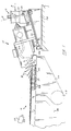
- the nozzles or slots 32 are configured and arranged to apply a greater volume of air along the conveyor edges, where the density of the overlapping pattern of rod rings is relatively great as compared to that at the conveyor centre. Under ideal conditions, where the ring pattern is being transported centrally along the conveyor, as illustrated in Figure 3, this prearrangement of slots or nozzles will achieve optimum metallurgical results by cooling the rod rings substantially uniformly.
- the present invention addresses this problem by mounting the laying head 10 on a platform 36 which is in turn carried on a fixed support structure 38.
- a pivot shaft 40 connects the platform 36 to the underlying support structure for pivotal movement about an axis "A" which intersects the delivery path P at the nip of the pinch rolls 16.
- the platform 36 has a bevelled forward edge 42 which circumscribes an arc having a radius extending from the pivotal axis A.
- a plurality of clamp assemblies 44 are mounted on the support structure 38 at spaced locations around the accurate forward edge of the platform.
- Each clamp assembly comprises a cylinder 46 containing a piston 48 with a rearwardly projecting bevelled nose 50 designed to coact in frictional engagement with the bevelled forward edge 42 of the platform 36 to firmly lock the platform in place on its underlying support structure 38.
- the piston 48 is yieldably urged into its engaged position by a coiled spring 52.
- Pressurised oil or air is introduced into the cylinder as at 54 to overcome the biasing action of the spring 52 and thereby shift the piston 48 and its bevelled nose 50 in a reverse direction, which in turn releases the platform 36 for pivotal movement abut axis A.
- a linear actuation 56 ( Figure 2) is connected at opposite ends to the platform 36 and support structure 38 to provide the means for pivotally adjusting the platform 36 and laying head 10 about axis A.
- the clamp assemblies 44 can be momentarily released to accommodate a corrective pivotal adjustment of the platform 36 and laying head 10. This will horizontally shift the direction of ring deposit on the conveyor, causing the ring pattern to return to the conveyor centre.
- a hot metal detector or camera 58 may be employed in conjunction with an appropriate control system 60 to monitor the position of rings on the conveyor and to automatically operate the clamp assemblies 44 and linear actuator 56.
- clamp assemblies 44 and linear actuator 56 may be modified or replaced by other equivalent components designed to achieve substantially the same results.
- the laying head may be shiftable laterally along with the pinch roll unit, with appropriate upstream guides being used to insure proper delivery of the product.
Landscapes
- Engineering & Computer Science (AREA)
- Mechanical Engineering (AREA)
- Heat Treatments In General, Especially Conveying And Cooling (AREA)
- Winding, Rewinding, Material Storage Devices (AREA)
- Metal Rolling (AREA)
- Heat Treatment Of Articles (AREA)
- Control Of Conveyors (AREA)
Applications Claiming Priority (2)
| Application Number | Priority Date | Filing Date | Title |
|---|---|---|---|
| US09/119,868 US6010088A (en) | 1998-07-21 | 1998-07-21 | Apparatus for centralizing rings being deposited in an overlapping pattern on a cooling conveyor |
| US119868 | 1998-07-21 |
Publications (2)
| Publication Number | Publication Date |
|---|---|
| EP0974407A2 true EP0974407A2 (fr) | 2000-01-26 |
| EP0974407A3 EP0974407A3 (fr) | 2002-03-20 |
Family
ID=22386877
Family Applications (1)
| Application Number | Title | Priority Date | Filing Date |
|---|---|---|---|
| EP99305792A Withdrawn EP0974407A3 (fr) | 1998-07-21 | 1999-07-21 | Dispositif de centrage de boucles de fil sur un transporteur de refroidissement |
Country Status (12)
| Country | Link |
|---|---|
| US (1) | US6010088A (fr) |
| EP (1) | EP0974407A3 (fr) |
| JP (1) | JP3030027B2 (fr) |
| KR (1) | KR100334216B1 (fr) |
| CN (1) | CN1247111A (fr) |
| AR (1) | AR019443A1 (fr) |
| BR (1) | BR9902838A (fr) |
| CA (1) | CA2277500A1 (fr) |
| ID (1) | ID23734A (fr) |
| PL (1) | PL334414A1 (fr) |
| RU (1) | RU2177384C2 (fr) |
| TW (1) | TW424012B (fr) |
Families Citing this family (4)
| Publication number | Priority date | Publication date | Assignee | Title |
|---|---|---|---|---|
| KR100928813B1 (ko) * | 2007-12-11 | 2009-11-27 | 주식회사 포스코 | 선재코일 이송안내장치 |
| US8707748B2 (en) * | 2010-07-01 | 2014-04-29 | Siemens Industry, Inc. | Turn down apparatus |
| US20140374526A1 (en) * | 2013-06-20 | 2014-12-25 | Siemens Industry, Inc. | Rolling mill laying head |
| US20220371077A1 (en) * | 2021-05-21 | 2022-11-24 | Primetals Technologies USA LLC | Method of Automating Coil Height Control in a Wire Rod Plant |
Citations (2)
| Publication number | Priority date | Publication date | Assignee | Title |
|---|---|---|---|---|
| US5052124A (en) | 1989-02-20 | 1991-10-01 | Toa Steel Co., Ltd. | Method for transporting hot-rolled wire rod and apparatus therefor |
| US5079937A (en) | 1989-12-09 | 1992-01-14 | Sms Schloemann-Siemag Aktiengesellschaft | Controllable conveyor arrangement for cooling rolled wire |
Family Cites Families (14)
| Publication number | Priority date | Publication date | Assignee | Title |
|---|---|---|---|---|
| DE1214635B (de) * | 1964-03-23 | 1966-04-21 | Schloemann Ag | Vorrichtung zum Kuehlen von mittel- und hoch-legiertem Walzdraht |
| DE1602355A1 (de) * | 1967-02-04 | 1970-08-27 | Schloemann Ag | Verfahren zum Ablegen von einem kontinuierlichen Drahtwindungsstrang auf ein mit horizontal angeordneter Foerderebene ausgebildetes Foerdermittel |
| IT1058568B (it) * | 1976-03-26 | 1982-05-10 | Properzi G | Procedimento ed apparecchiatura per la raccolta di vergella o simile all uscita di un laminatoio |
| JPS5477260A (en) * | 1977-12-01 | 1979-06-20 | Toshiba Corp | Laying head positioning control unit |
| JPS5619924A (en) * | 1979-07-30 | 1981-02-25 | Nippon Steel Corp | Cooling apparatus for ring forming work from hot rolled rod material |
| JPS58192618A (ja) * | 1982-05-06 | 1983-11-10 | Kawasaki Steel Corp | 熱間圧延線材の精製装置 |
| JPS61180427A (ja) * | 1985-02-06 | 1986-08-13 | Canon Inc | 集積回路基板 |
| US4914935A (en) * | 1988-12-28 | 1990-04-10 | Fryer Corporation | Method and apparatus for laying coiled rod stock |
| JPH06102217B2 (ja) * | 1990-03-30 | 1994-12-14 | 新日本製鐵株式会社 | 線材コイルの集束方法、装置及びリング径測定装置 |
| US5170653A (en) * | 1990-09-07 | 1992-12-15 | Bethlehem Steel Corporation | Method for coiling twist free steel bars |
| DE4232497C2 (de) * | 1991-09-30 | 1997-03-13 | Mitsubishi Motors Corp | Vorrichtung zur Positionierung einer Karosserie auf einem Förderer |
| US5312065A (en) * | 1992-02-05 | 1994-05-17 | Morgan Construction Company | Rod laying head with front and tail end ring control |
| US5273231A (en) * | 1992-08-03 | 1993-12-28 | Morgan Construction Company | Loop distributor for reforming station |
| JPH0929330A (ja) * | 1995-07-20 | 1997-02-04 | Kobe Steel Ltd | レイングヘッド先端位置制御方法 |
-
1998
- 1998-07-21 US US09/119,868 patent/US6010088A/en not_active Expired - Fee Related
-
1999
- 1999-07-12 CA CA002277500A patent/CA2277500A1/fr not_active Abandoned
- 1999-07-13 TW TW088111879A patent/TW424012B/zh not_active IP Right Cessation
- 1999-07-15 PL PL99334414A patent/PL334414A1/xx unknown
- 1999-07-16 JP JP11203424A patent/JP3030027B2/ja not_active Expired - Fee Related
- 1999-07-20 BR BR9902838-7A patent/BR9902838A/pt unknown
- 1999-07-20 KR KR1019990029214A patent/KR100334216B1/ko not_active Expired - Fee Related
- 1999-07-20 RU RU99115782/02A patent/RU2177384C2/ru not_active IP Right Cessation
- 1999-07-21 AR ARP990103586A patent/AR019443A1/es unknown
- 1999-07-21 CN CN99110659A patent/CN1247111A/zh active Pending
- 1999-07-21 ID IDP990687D patent/ID23734A/id unknown
- 1999-07-21 EP EP99305792A patent/EP0974407A3/fr not_active Withdrawn
Patent Citations (2)
| Publication number | Priority date | Publication date | Assignee | Title |
|---|---|---|---|---|
| US5052124A (en) | 1989-02-20 | 1991-10-01 | Toa Steel Co., Ltd. | Method for transporting hot-rolled wire rod and apparatus therefor |
| US5079937A (en) | 1989-12-09 | 1992-01-14 | Sms Schloemann-Siemag Aktiengesellschaft | Controllable conveyor arrangement for cooling rolled wire |
Also Published As
| Publication number | Publication date |
|---|---|
| CN1247111A (zh) | 2000-03-15 |
| KR20000016956A (ko) | 2000-03-25 |
| JP3030027B2 (ja) | 2000-04-10 |
| PL334414A1 (en) | 2000-01-31 |
| TW424012B (en) | 2001-03-01 |
| CA2277500A1 (fr) | 2000-01-21 |
| AR019443A1 (es) | 2002-02-20 |
| EP0974407A3 (fr) | 2002-03-20 |
| RU2177384C2 (ru) | 2001-12-27 |
| US6010088A (en) | 2000-01-04 |
| ID23734A (id) | 2000-05-11 |
| KR100334216B1 (ko) | 2002-05-02 |
| JP2000033415A (ja) | 2000-02-02 |
| BR9902838A (pt) | 2000-02-15 |
Similar Documents
| Publication | Publication Date | Title |
|---|---|---|
| US7059161B2 (en) | Thin-strip coiler comprising a flatness measuring roll | |
| EP0936275A1 (fr) | Dispositif de réglage de tension d'une bande dans une installation de recuit en continu de bandes en acier | |
| US6010088A (en) | Apparatus for centralizing rings being deposited in an overlapping pattern on a cooling conveyor | |
| JP4334539B2 (ja) | 一つのステッケル圧延スタンドにより帯状材を熱間圧延する方法と装備 | |
| EP1977839A1 (fr) | Rouleau de repassage à double pivot | |
| JP2533708B2 (ja) | 熱間圧延鋼板の巻取り装置 | |
| US7861567B2 (en) | Method and apparatus to control the lateral motion of a long metal bar being formed by a mechanical process such as rolling or drawing | |
| US7318267B2 (en) | Strip production equipment | |
| US11999015B2 (en) | System and method for cutting film | |
| RU2095173C1 (ru) | Устройство для центрирования рулонного материала | |
| US5597132A (en) | Tape winding device providing uniform winding and rapid installation and removal of winding arm | |
| JP3328186B2 (ja) | 縦型ルーパにおける帯状材の偏り修正方法および装置 | |
| CZ9902574A3 (cs) | Zařízení na vystřeďování prstenců umísťovaných v překrývajícím se vzoru na chladicí dopravník | |
| JP3999349B2 (ja) | スパイラル鋼管の成形装置 | |
| KR20060018302A (ko) | 선재압연설비의 가변식 터널 가이드장치 | |
| JPH06156827A (ja) | 長尺体巻取方法及びその装置 | |
| KR200227322Y1 (ko) | 압연권취기용벨트라퍼톱프레이트갭조정장치 | |
| JPH105867A (ja) | ストリップコイルの鼻曲げ装置およびストリップ処理ライン | |
| KR950008919Y1 (ko) | 선재압연의 가레트라인(Garret Line) 곡선 가이드 장치 | |
| KR20040015860A (ko) | 코일 선단부 유도장치 | |
| JP3349425B2 (ja) | 厚板圧延方法およびその装置 | |
| JP2005074781A (ja) | ストライプ状樹脂フィルム積層金属板の製造方法および製造装置 | |
| RU8955U1 (ru) | Устройство для проводки ленточного материала | |
| KR101060895B1 (ko) | 강판 연속라인의 오프너장치 | |
| JPH0797111A (ja) | プロセスラインにおけるストリップの蛇行修正装置ならびにその使用方法 |
Legal Events
| Date | Code | Title | Description |
|---|---|---|---|
| PUAI | Public reference made under article 153(3) epc to a published international application that has entered the european phase |
Free format text: ORIGINAL CODE: 0009012 |
|
| AK | Designated contracting states |
Kind code of ref document: A2 Designated state(s): AT BE CH CY DE DK ES FI FR GB GR IE IT LI LU MC NL PT SE |
|
| AX | Request for extension of the european patent |
Free format text: AL;LT;LV;MK;RO;SI |
|
| PUAL | Search report despatched |
Free format text: ORIGINAL CODE: 0009013 |
|
| AK | Designated contracting states |
Kind code of ref document: A3 Designated state(s): AT BE CH CY DE DK ES FI FR GB GR IE IT LI LU MC NL PT SE |
|
| AX | Request for extension of the european patent |
Free format text: AL;LT;LV;MK;RO;SI |
|
| RIC1 | Information provided on ipc code assigned before grant |
Free format text: 7B 21C 47/26 A, 7C 21D 9/573 B |
|
| 17P | Request for examination filed |
Effective date: 20020223 |
|
| AKX | Designation fees paid |
Free format text: AT BE CH CY DE DK ES FI FR GB GR IE IT LI LU MC NL PT SE |
|
| 17Q | First examination report despatched |
Effective date: 20030520 |
|
| STAA | Information on the status of an ep patent application or granted ep patent |
Free format text: STATUS: THE APPLICATION IS DEEMED TO BE WITHDRAWN |
|
| 18D | Application deemed to be withdrawn |
Effective date: 20031001 |