EP0974858A2 - Dispositif de support pour miroir de guidage d'un rayon laser dans une machine d'usinage au laser et fixage de miroir faisant partie du dispositif de support - Google Patents
Dispositif de support pour miroir de guidage d'un rayon laser dans une machine d'usinage au laser et fixage de miroir faisant partie du dispositif de support Download PDFInfo
- Publication number
- EP0974858A2 EP0974858A2 EP99111820A EP99111820A EP0974858A2 EP 0974858 A2 EP0974858 A2 EP 0974858A2 EP 99111820 A EP99111820 A EP 99111820A EP 99111820 A EP99111820 A EP 99111820A EP 0974858 A2 EP0974858 A2 EP 0974858A2
- Authority
- EP
- European Patent Office
- Prior art keywords
- support
- mirror surface
- surface support
- base body
- mirror
- Prior art date
- Legal status (The legal status is an assumption and is not a legal conclusion. Google has not performed a legal analysis and makes no representation as to the accuracy of the status listed.)
- Granted
Links
- 238000012545 processing Methods 0.000 title claims abstract description 10
- 238000005266 casting Methods 0.000 claims abstract description 14
- 150000001875 compounds Chemical class 0.000 claims abstract description 4
- 239000000945 filler Substances 0.000 claims description 26
- 238000003860 storage Methods 0.000 claims description 25
- 239000002184 metal Substances 0.000 claims description 21
- 238000012856 packing Methods 0.000 claims description 6
- 230000000149 penetrating effect Effects 0.000 claims description 2
- 230000015572 biosynthetic process Effects 0.000 description 5
- 238000004519 manufacturing process Methods 0.000 description 5
- 238000013459 approach Methods 0.000 description 4
- 238000005520 cutting process Methods 0.000 description 4
- 238000012549 training Methods 0.000 description 4
- 238000013461 design Methods 0.000 description 3
- 238000006073 displacement reaction Methods 0.000 description 3
- 239000000853 adhesive Substances 0.000 description 2
- 230000001070 adhesive effect Effects 0.000 description 2
- 238000005452 bending Methods 0.000 description 2
- 230000000694 effects Effects 0.000 description 2
- 239000007788 liquid Substances 0.000 description 2
- 230000006978 adaptation Effects 0.000 description 1
- 230000002411 adverse Effects 0.000 description 1
- 230000037237 body shape Effects 0.000 description 1
- 239000003795 chemical substances by application Substances 0.000 description 1
- 238000005553 drilling Methods 0.000 description 1
- 238000009434 installation Methods 0.000 description 1
- 238000003754 machining Methods 0.000 description 1
- 239000000463 material Substances 0.000 description 1
- 238000007789 sealing Methods 0.000 description 1
- 230000035939 shock Effects 0.000 description 1
- 239000007787 solid Substances 0.000 description 1
- 238000007711 solidification Methods 0.000 description 1
- 230000008023 solidification Effects 0.000 description 1
- 238000012360 testing method Methods 0.000 description 1
- 238000009423 ventilation Methods 0.000 description 1
Images




Classifications
-
- G—PHYSICS
- G02—OPTICS
- G02B—OPTICAL ELEMENTS, SYSTEMS OR APPARATUS
- G02B7/00—Mountings, adjusting means, or light-tight connections, for optical elements
- G02B7/18—Mountings, adjusting means, or light-tight connections, for optical elements for prisms; for mirrors
- G02B7/182—Mountings, adjusting means, or light-tight connections, for optical elements for prisms; for mirrors for mirrors
- G02B7/1822—Mountings, adjusting means, or light-tight connections, for optical elements for prisms; for mirrors for mirrors comprising means for aligning the optical axis
- G02B7/1824—Manual alignment
- G02B7/1825—Manual alignment made by screws, e.g. for laser mirrors
-
- B—PERFORMING OPERATIONS; TRANSPORTING
- B23—MACHINE TOOLS; METAL-WORKING NOT OTHERWISE PROVIDED FOR
- B23K—SOLDERING OR UNSOLDERING; WELDING; CLADDING OR PLATING BY SOLDERING OR WELDING; CUTTING BY APPLYING HEAT LOCALLY, e.g. FLAME CUTTING; WORKING BY LASER BEAM
- B23K26/00—Working by laser beam, e.g. welding, cutting or boring
- B23K26/02—Positioning or observing the workpiece, e.g. with respect to the point of impact; Aligning, aiming or focusing the laser beam
- B23K26/035—Aligning the laser beam
Definitions
- the invention relates to a storage for a mirror for guidance a laser beam on a laser processing machine, with at least one mirror surface support held on a base body and an adjusting device for adjusting the Mirror surface support in a target position relative to the base body.
- the invention further relates to a mirror surface support as part of such storage.
- a known storage of the type mentioned serves the Setting a mirror surface for guiding the laser beam in the Inside the resonator and makes use of an adjustment device with adjustment screws that have a mirror surface support enforce and in the forming a basic body Resonator block are screwed.
- the mirror surface support and with this the mirror surface can be turned in relation to the base body swivel and thereby to guide the laser beam in the Align the inside of the resonator exactly.
- the in the adjustment of that Mirror surface bracket described pivot angle are in the Of the order of a few thousandths of a degree.
- the previously known Adjusting screws also serve to fasten the mirror surface support on the resonator block.
- the self-locking Formation of the threads of the adjusting screws causes the Mirror surface support opposite its position once set maintains the resonator block permanently.
- the present invention has to provide set the goal.
- the object of preventing a Misalignment of the mirror surfaces in that in the case of generic Bearings in addition to the adjustment device at least a support device is provided between the Mirror surface support and the base body is arranged and over which the mirror surface support is in the target position supported on the base body against changes in position.
- the said Support device serves to secure the by means of the adjustment device made adjustment of the mirror surface support and thus the mirror surface in the target position. To this Way provides an effective way to a misalignment of the mirror surface to guide the laser beam counteract.
- the support device at least one support body comprises, on the one hand, associated with the mirror surface support Abutment and on the other hand on the base body associated abutment is supported.
- the support body of bearings according to the invention can be designed like a tab and / or as sheet metal parts.
- Support body types make another preferred embodiment the invention use of a support body in the form of a Filler, which has a space between the mirror surface support and the abutment assigned to the base body at least partially filled out.
- the filler is in the interest of simple, dimensionally accurate production preferably designed as a cast body.
- the bearing protrusion mentioned can with the remaining mirror surface support or the rest of the main body in one piece from the Be fully made. So that the mirror surface support despite its securing in the target position of the base body without major Effort can be reduced is the last in further training described embodiment of the inventive bearings but provided that the at least one bearing projection one Sleeve and a penetrating the sleeve in the axial direction Includes bolts, the sleeve with its outer wall one the abutment for the support or filler forms and the Bolt detachably on the mirror surface support provided with the bearing projection or base body is attached. To separate from In this case, the mirror surface support and base body are merely to loosen the said bolt. Then the Remove mirror surface support from the base body, the Sleeve can remain inside the receptacle provided it is there is determined by the support or filler.
- a double function as a safety and fastening device can the support device in the case of a type of take over storage according to the invention, which are characterized is that the mirror surface support by means of the support device is attached to the base body.
- the above, related to the mirror surface support is achieved in that the mirror surface support in the target position on the base body with formation of a space between the mirror surface support and the main body is held and at least one in the space opening feed channel for a solidifying and has the casting compound forming the filling or casting body.
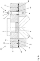
- a mounting 1 for a mirror 2 is included a mirror surface support on a laser processing machine 3, which supports the mirror 2 provided with a mirror surface 4.
- the mirror surface 4 serves to guide a laser beam 5 inside a resonator block forming a basic body 6.
- To adjust the mirror surface support 3 and thus the Mirror surface 4 opposite the resonator block 6 has the storage 1 an adjusting device 7 with a total of three over the Mirror surface support 3 distributed threaded bolts 8th with lock nuts 9. Of the three threaded bolts 8 and lock nuts 9 is only a single or one recognizable.
- the threaded bolt 8 is in the form of a tool engagement Hexagon socket 10 provided by the mirror surface support 3 passed with radial play and with the resonator block 6 screwed.
- the adjusting nut 9 is relative to the threaded bolt 8 rotatably screwed onto it and supports itself with it crowned underside on the mirror surface support 3.
- the Mirror surface support 3 in turn rests on disc springs 11 which are penetrated by the threaded bolt 8 on the resonator block 6.
- Direct contact between the mirror surface support 3 and the resonator block 6 results on a spherical cap Approach 12 of the mirror surface support 3, which on supports an opposite wall of the resonator block 6.
- a spherical cap Approach 12 of the mirror surface support 3 which on supports an opposite wall of the resonator block 6.
- an O-ring 13 is used against the exterior of the resonator.
- a support device is used in the form of a cast or filler body 14. This fills the space from between a wall 15 of a receptacle 16 of the Mirror surface support 3 and a wall 17 one in the recording 16 engaging bearing projection 18 of the resonator block 6. In the axial direction of the bearing projection 18 is the casting or Filler 14 receiving space between the walls 15, 17 limited by O-rings 19. Via a feed channel 20 and a ventilation channel 21 is the space mentioned in connection with the outside of the mirror surface support 3.
- a hardening agent was used to produce the cast or filler body 14 Plastic in a liquid state through the feed channel 20 in the space delimited by the O-rings 19 between the Walls 15, 17 of the receptacle 16 and the bearing projection 18 pressed in.
- the air initially contained in the space was able to escape through vent duct 21.
- the casting or Filler body 14 By the solidification of the liquid plastic was the casting or Filler body 14, by means of which the mirror surface support 3 in the previously set by means of the adjusting device 7 Sollage is effectively and permanently secured.
- the wall 15 of the Recording 16 forms the mirror surface support 3, the wall 17 of the bearing projection 18 that assigned to the resonator block 6 Abutment for the casting or filler 14.
- Bearings 31, 61, as shown in Figures 1b and 1c are different from the storage 1 according to FIG essentially by the arrangement and the specific design of the respective casting or packing.
- For each other Components are the same in Figures 1a, 1b and 1c Reference numerals used.
- the bearing 31 according to Figure 1b makes use of a cast or Packing 44, the between each other and as Abutment for the cast or filler 44 serving surfaces 45, 47 of the mirror surface support 3 and the resonator block 6 is formed. It is limited by the cast or Packing 44 filled space of concentrically arranged O-rings 49, which also serve the beam guidance space to seal the resonator block 6 to the outside.
- a spherical cap-like provided for this purpose according to FIG. 1a Approach is consequently on the mirror surface support 3 according to FIG. 1b not mandatory.
- the cast or filler body 44 acts by displacement of the mirror surface support 3 towards the resonator block 6 opposite.
- the casting or filler 44 secures in the opposite direction the mirror surface support 3 in the desired position relative to the resonator block 6 by a non-positive adhesive connection of the above Art already described.
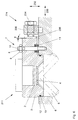
- a bearing 91 shown in FIGS. 2a and 2b differentiates essentially from the storage 1 according to FIG. 1a by the formation of that provided on the resonator block 6 Bearing ledge.
- the reference numerals used in Figure 1a intended.
- FIG. 2b is a bearing projection 108 of the resonator block 6 formed by a screw 112 and a sleeve 113.
- the screw 112 With its bolt 114, the screw 112 is detachable into a corresponding one Thread on the resonator block 6 screwed.
- the Sleeve 113 surrounds the pin 114 in the area of the receptacle 16 of the mirror surface support 3 concentrically. In installation position the sleeve 113 on her lying from the resonator block 6 End over a head 115 of the screw 112 towards the Resonator block 6 applied and thereby between the head 115 the screw 112 and the resonator block 6 clamped.
- the mirror surface support 3 can be used regardless of it of the cast or filler 14 accomplished fuse in the debit position, for example, to exchange for another Remove the mirror surface support from the resonator block 6. To this The only purpose is to loosen screw 112. A corresponding Rotational movement of screw 112 is easily possible after only about the cast or filler 14 Sleeve 113 with the mirror surface support 3 and others. twist test connected is the rotational mobility of the screw 112 relative to the Sleeve 113 is not affected by this.
- the storage is on the mirror surface support 3 91 a total of four of the shown in Figure 2b in detail Units from screw 112 and sleeve 113 with associated Cast or filler 14 provided. Before removing the Mirror surface support 3 from the resonator block 6 are self-evident loosen all screws 112.
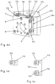
- Bearings 121, 151, 181, as shown in Figures 3, 4a and 5 are shown differ from those described above Bearings 1, 31, 61, 91 essentially by that no cast or filler body is used as a support body.
- the tab-like sheet metal part 134 according to FIG. 3 is non-cutting Forming a sheet metal strip has been manufactured.
- Forming was given a shape to the tab-like sheet metal part 134, which enables both the located mirror surface support 3 and on the resonator block 6 to support large areas and thereby the mirror surface support 3 to effectively secure in its target position.
- As an abutment boundary surfaces serve directly for the tab-like sheet metal part 134 the mirror surface support 3 and the resonator block 6.
- the tab-like sheet metal parts 164 which are mounted in FIG State and shown individually in FIG. 4c, were obtained from a corresponding laser beam Cut out sheet of metal. In the course of their manufacture, they are tab-like sheet metal parts 164 by cutting processing also provided with slots 172 by means of a laser beam been.
- the slots 172 allow only small bending forces Required deformation of the tab-like sheet metal parts 164 for the purpose of adapting them to the orientation of the abutment used surface on the mirror surface support to be secured in the target position 3.
- slots 172 By bending around by the longitudinal direction bend line represented by slots 172 may include tabs 173 be aligned with little effort so that they after screwing the tab-like sheet metal parts 164 with the Resonator block 6 over a large area on the relevant wall surface of the in the target position of the adjusted mirror surface support 3. Also with the mirror surface support 3, the tab-like sheet metal parts 164 connected by fastening screws.
- Figure 4b shows a possible alternative to the tab-like Sheet metal parts 164.
- the sheet metal part according to FIG. 4b is also with a Provide slot 172, the deformation of the sheet metal part if necessary facilitated.
- the support block 194 shown in FIG. 5 is in contrast to the tab-like sheet metal parts 134 described above, 164 made from solid.
- By appropriate machining surfaces of the support block 194 became a blank created that are aligned so that at Support of the support block 194 on the resonator block 6 a Large-area support of the mirror surface support in the target position 3 is guaranteed.
- the is on the in the target position mirror surface support 3 adjacent surface of the support block 194 by the same angle ⁇ against the normal to the bearing surface of the support block 194 on the resonator block 6 inclined as that as an abutment for the support block 194 serving surface of the mirror surface support 3.
- the angle is ⁇ shown in Figure 5 greatly exaggerated in size.
- a two-axis deliverability of a support body 224 opposite the associated mirror surface support 3 and the relevant one Resonator block 6 is realized in the case of storage 211 according to FIG. 6.
- the support body 224 can be used both in Direction of a double arrow 232 as well as in the direction of a Double arrow 233 are delivered.
- Set screws 234, 235 are provided, the set screw 235 the set screw 234 inside one with an internal thread provided bore in which the external thread on the Bolt of the set screw 234 engages.
- the support body 224 can be due the adjustment options described by means of Set screws 234, 235 and due to the movable bearing the support plate 236 with the latter on the associated abutment surface brought the surface of the mirror surface 3 to the plant and then for a permanently effective backup the mirror surface support 3 in the target position. Also grant the adjustment options mentioned a certain freedom when choosing the location of the adjusting screw 235 on the resonator block 6. By adjusting the adjusting screws accordingly 234, 235 can be any existing initially Distances between the support plate 236 and the relevant one Compensate the abutment surface of the mirror surface support 3.
Landscapes
- Physics & Mathematics (AREA)
- Optics & Photonics (AREA)
- Engineering & Computer Science (AREA)
- Plasma & Fusion (AREA)
- Mechanical Engineering (AREA)
- General Physics & Mathematics (AREA)
- Mounting And Adjusting Of Optical Elements (AREA)
- Lasers (AREA)
- Laser Beam Processing (AREA)
Applications Claiming Priority (2)
| Application Number | Priority Date | Filing Date | Title |
|---|---|---|---|
| DE29813064U | 1998-07-22 | ||
| DE29813064U DE29813064U1 (de) | 1998-07-22 | 1998-07-22 | Lagerung für einen Spiegel zur Führung eines Laserstrahls an einer Laserbearbeitungsmaschine sowie Spiegelflächenträger als Teil einer derartigen Lagerung |
Publications (3)
| Publication Number | Publication Date |
|---|---|
| EP0974858A2 true EP0974858A2 (fr) | 2000-01-26 |
| EP0974858A3 EP0974858A3 (fr) | 2000-11-08 |
| EP0974858B1 EP0974858B1 (fr) | 2006-09-13 |
Family
ID=8060231
Family Applications (1)
| Application Number | Title | Priority Date | Filing Date |
|---|---|---|---|
| EP99111820A Expired - Lifetime EP0974858B1 (fr) | 1998-07-22 | 1999-06-19 | Dispositif de support pour miroir de guidage d'un rayon laser dans une machine d'usinage au laser et fixage de miroir faisant partie du dispositif de support |
Country Status (3)
| Country | Link |
|---|---|
| EP (1) | EP0974858B1 (fr) |
| AT (1) | ATE339703T1 (fr) |
| DE (2) | DE29813064U1 (fr) |
Cited By (2)
| Publication number | Priority date | Publication date | Assignee | Title |
|---|---|---|---|---|
| EP1235090A1 (fr) * | 2001-02-22 | 2002-08-28 | TRUMPF LASERTECHNIK GmbH | Dispositif de guidage d'un faisceau laser |
| EP1649967A1 (fr) * | 2004-10-20 | 2006-04-26 | Trumpf Werkzeugmaschinen GmbH + Co. KG | Elément optique pour une tête d'usinage au laser |
Family Cites Families (10)
| Publication number | Priority date | Publication date | Assignee | Title |
|---|---|---|---|---|
| CA545976A (fr) * | 1957-09-10 | F. Salminen Ilmari | Emulsions photographiques contenant des agents developpeur de tannage | |
| US3436050A (en) | 1967-05-04 | 1969-04-01 | Dawson Inc Alexander | Adjustable mount for optical element |
| US3700313A (en) | 1971-12-27 | 1972-10-24 | Trw Inc | Coaxially adjusted optical mount |
| DE3644049A1 (de) | 1986-12-22 | 1988-06-30 | Siemens Ag | Justiervorrichtung fuer ein optisches element |
| JPH01228691A (ja) * | 1988-03-08 | 1989-09-12 | Mitsubishi Electric Corp | レーザ加工機用ベンドミラー |
| US4863243A (en) * | 1988-05-09 | 1989-09-05 | Eastman Kodak Company | Mount for an optical element including a holder with a generally semicylindrical surface |
| JPH0275491A (ja) | 1988-09-07 | 1990-03-15 | Fanuc Ltd | レーザビームベンダ |
| JPH0728069B2 (ja) * | 1989-02-15 | 1995-03-29 | 三菱電機株式会社 | レーザ発振器 |
| JP3076111B2 (ja) * | 1991-10-15 | 2000-08-14 | 株式会社アマダ | レーザ加工装置のベンドミラー取付構造 |
| JPH05273450A (ja) * | 1992-03-25 | 1993-10-22 | Toshiba Corp | 光学ヘッドとこの光学ヘッドにおける光学素子の固定方法 |
-
1998
- 1998-07-22 DE DE29813064U patent/DE29813064U1/de not_active Expired - Lifetime
-
1999
- 1999-06-19 EP EP99111820A patent/EP0974858B1/fr not_active Expired - Lifetime
- 1999-06-19 DE DE59913846T patent/DE59913846D1/de not_active Expired - Lifetime
- 1999-06-19 AT AT99111820T patent/ATE339703T1/de not_active IP Right Cessation
Cited By (3)
| Publication number | Priority date | Publication date | Assignee | Title |
|---|---|---|---|---|
| EP1235090A1 (fr) * | 2001-02-22 | 2002-08-28 | TRUMPF LASERTECHNIK GmbH | Dispositif de guidage d'un faisceau laser |
| EP1649967A1 (fr) * | 2004-10-20 | 2006-04-26 | Trumpf Werkzeugmaschinen GmbH + Co. KG | Elément optique pour une tête d'usinage au laser |
| US7947923B2 (en) | 2004-10-20 | 2011-05-24 | Trumpf Werkzeugmaschinen Gmbh + Co. Kg | Encoded optical element of a laser processing head |
Also Published As
| Publication number | Publication date |
|---|---|
| EP0974858A3 (fr) | 2000-11-08 |
| ATE339703T1 (de) | 2006-10-15 |
| DE29813064U1 (de) | 1998-10-29 |
| EP0974858B1 (fr) | 2006-09-13 |
| DE59913846D1 (de) | 2006-10-26 |
Similar Documents
| Publication | Publication Date | Title |
|---|---|---|
| EP0644976B1 (fr) | Charniere | |
| DE69406433T2 (de) | Schneidwerkzeug mit einem werkzeughalter mit einem ersetzbaren einsatz | |
| EP0282090B1 (fr) | Fraise à plaquettes | |
| DE3125746C2 (de) | Schrauben-Differentialbetätigungseinrichtung | |
| DE69718740T2 (de) | Werkzeugmaschinenschneidewerkzeugpositioniervorrichtung | |
| DE20117159U1 (de) | Werkzeugmaschine mit Befestigungsflansch | |
| DE20116015U1 (de) | Klemmvorrichtung zum Klemmen von Trägern | |
| DE102021133934B3 (de) | Kardanische Aufhängungsstruktur und Beleuchtungseinrichtung | |
| DE8336030U1 (de) | Vorrichtung zum verschwenken einer werkzeugaufnahmevorrichtung, insbesondere eines winkelfraeskopfes, am freien (unteren) ende eines fraesspindelschlittens | |
| DE69306293T2 (de) | Schneidenhalter für Granuliervorrichtung | |
| EP0306626B1 (fr) | Dispositif de réglage de la tringlerie de direction d'une roue | |
| EP0759377B1 (fr) | Dispositif de réglage de l'angle d'inclinaison d'un réflecteur de phare de véhicule | |
| DE69124785T2 (de) | Verfahren zum verbinden zweier bauteile mit hilfe eines verstellbaren halters und gestell zum gebrauch mit diesem verfahren | |
| EP0974858A2 (fr) | Dispositif de support pour miroir de guidage d'un rayon laser dans une machine d'usinage au laser et fixage de miroir faisant partie du dispositif de support | |
| DE2736387C2 (de) | Zerspanungswerkzeug | |
| DE2854121C2 (de) | An ein Maschinenteil ansetzbare Vorrichtung zum Ausstechen von Ringlippen dort in Bohrungen eingestemmter Lagerbüchsen | |
| DE102012112362C5 (de) | Ventil mit einer Befestigungseinrichtung | |
| DE3341507A1 (de) | Werkzeug zum honen von bohrungen bzw. wellen oder dgl. | |
| DE19920521C2 (de) | Ausrichtvorrichtung zum Einpassen eines Kraftfahrzeugschweinwerfers in einen Karosserieausschnitt | |
| DE102005050594A1 (de) | Schraubenmutter zur Drehmomentbegrenzung und Verwendung solch einer Schraubenmutter in einem Haltermodul zur Klemmkraftbegrenzung | |
| DE4216612A1 (de) | Einachsscharnier | |
| DE29622974U1 (de) | Befestigungsvorrichtung | |
| EP0410129B1 (fr) | Outil de coupe | |
| DE102006050132B3 (de) | Statisch überbestimmte Lagerung eines Antriebsaggregats eines Kraftfahrzeugs | |
| DE69500645T2 (de) | Vorrichtung zum Befestigen einer elastischen Verbindung auf einer Wiege |
Legal Events
| Date | Code | Title | Description |
|---|---|---|---|
| PUAI | Public reference made under article 153(3) epc to a published international application that has entered the european phase |
Free format text: ORIGINAL CODE: 0009012 |
|
| AK | Designated contracting states |
Kind code of ref document: A2 Designated state(s): AT CH DE FR GB IT LI |
|
| AX | Request for extension of the european patent |
Free format text: AL;LT;LV;MK;RO;SI |
|
| PUAL | Search report despatched |
Free format text: ORIGINAL CODE: 0009013 |
|
| AK | Designated contracting states |
Kind code of ref document: A3 Designated state(s): AT BE CH CY DE DK ES FI FR GB GR IE IT LI LU MC NL PT SE |
|
| AX | Request for extension of the european patent |
Free format text: AL;LT;LV;MK;RO;SI |
|
| RIC1 | Information provided on ipc code assigned before grant |
Free format text: 7G 02B 7/198 A, 7G 02B 7/182 B, 7B 23K 26/02 B |
|
| 17P | Request for examination filed |
Effective date: 20010217 |
|
| AKX | Designation fees paid |
Free format text: AT CH DE FR GB IT LI |
|
| 17Q | First examination report despatched |
Effective date: 20040225 |
|
| GRAP | Despatch of communication of intention to grant a patent |
Free format text: ORIGINAL CODE: EPIDOSNIGR1 |
|
| GRAS | Grant fee paid |
Free format text: ORIGINAL CODE: EPIDOSNIGR3 |
|
| GRAA | (expected) grant |
Free format text: ORIGINAL CODE: 0009210 |
|
| AK | Designated contracting states |
Kind code of ref document: B1 Designated state(s): AT CH DE FR GB IT LI |
|
| PG25 | Lapsed in a contracting state [announced via postgrant information from national office to epo] |
Ref country code: IT Free format text: LAPSE BECAUSE OF FAILURE TO SUBMIT A TRANSLATION OF THE DESCRIPTION OR TO PAY THE FEE WITHIN THE PRESCRIBED TIME-LIMIT;WARNING: LAPSES OF ITALIAN PATENTS WITH EFFECTIVE DATE BEFORE 2007 MAY HAVE OCCURRED AT ANY TIME BEFORE 2007. THE CORRECT EFFECTIVE DATE MAY BE DIFFERENT FROM THE ONE RECORDED. Effective date: 20060913 Ref country code: GB Free format text: LAPSE BECAUSE OF FAILURE TO SUBMIT A TRANSLATION OF THE DESCRIPTION OR TO PAY THE FEE WITHIN THE PRESCRIBED TIME-LIMIT Effective date: 20060913 |
|
| REG | Reference to a national code |
Ref country code: GB Ref legal event code: FG4D Free format text: NOT ENGLISH |
|
| RIN1 | Information on inventor provided before grant (corrected) |
Inventor name: HAECKER, MICHAEL DIPL.-ING. Inventor name: ANDREASCH, WOLFGANG DR.ING. |
|
| REG | Reference to a national code |
Ref country code: CH Ref legal event code: EP |
|
| REF | Corresponds to: |
Ref document number: 59913846 Country of ref document: DE Date of ref document: 20061026 Kind code of ref document: P |
|
| GBV | Gb: ep patent (uk) treated as always having been void in accordance with gb section 77(7)/1977 [no translation filed] |
Effective date: 20060913 |
|
| EN | Fr: translation not filed | ||
| PLBE | No opposition filed within time limit |
Free format text: ORIGINAL CODE: 0009261 |
|
| STAA | Information on the status of an ep patent application or granted ep patent |
Free format text: STATUS: NO OPPOSITION FILED WITHIN TIME LIMIT |
|
| 26N | No opposition filed |
Effective date: 20070614 |
|
| PG25 | Lapsed in a contracting state [announced via postgrant information from national office to epo] |
Ref country code: FR Free format text: LAPSE BECAUSE OF FAILURE TO SUBMIT A TRANSLATION OF THE DESCRIPTION OR TO PAY THE FEE WITHIN THE PRESCRIBED TIME-LIMIT Effective date: 20070518 |
|
| PGFP | Annual fee paid to national office [announced via postgrant information from national office to epo] |
Ref country code: AT Payment date: 20080529 Year of fee payment: 10 |
|
| PG25 | Lapsed in a contracting state [announced via postgrant information from national office to epo] |
Ref country code: FR Free format text: LAPSE BECAUSE OF FAILURE TO SUBMIT A TRANSLATION OF THE DESCRIPTION OR TO PAY THE FEE WITHIN THE PRESCRIBED TIME-LIMIT Effective date: 20060913 |
|
| PG25 | Lapsed in a contracting state [announced via postgrant information from national office to epo] |
Ref country code: AT Free format text: LAPSE BECAUSE OF NON-PAYMENT OF DUE FEES Effective date: 20090619 |
|
| PGFP | Annual fee paid to national office [announced via postgrant information from national office to epo] |
Ref country code: DE Payment date: 20180625 Year of fee payment: 20 Ref country code: CH Payment date: 20180621 Year of fee payment: 20 |
|
| REG | Reference to a national code |
Ref country code: DE Ref legal event code: R071 Ref document number: 59913846 Country of ref document: DE |
|
| REG | Reference to a national code |
Ref country code: CH Ref legal event code: PL |