EP0976012B1 - Systeme de microprocesseur pour systemes de regulation a securite critique - Google Patents
Systeme de microprocesseur pour systemes de regulation a securite critique Download PDFInfo
- Publication number
- EP0976012B1 EP0976012B1 EP98913559A EP98913559A EP0976012B1 EP 0976012 B1 EP0976012 B1 EP 0976012B1 EP 98913559 A EP98913559 A EP 98913559A EP 98913559 A EP98913559 A EP 98913559A EP 0976012 B1 EP0976012 B1 EP 0976012B1
- Authority
- EP
- European Patent Office
- Prior art keywords
- units
- central
- systems
- data processing
- read
- Prior art date
- Legal status (The legal status is an assumption and is not a legal conclusion. Google has not performed a legal analysis and makes no representation as to the accuracy of the status listed.)
- Expired - Lifetime
Links
- 230000015654 memory Effects 0.000 claims abstract description 43
- 230000006870 function Effects 0.000 claims abstract description 22
- 238000012360 testing method Methods 0.000 claims abstract description 16
- 238000012545 processing Methods 0.000 claims description 47
- 238000000034 method Methods 0.000 claims description 3
- 238000003860 storage Methods 0.000 abstract description 21
- 230000002093 peripheral effect Effects 0.000 abstract description 9
- 230000015556 catabolic process Effects 0.000 abstract 1
- 230000002950 deficient Effects 0.000 abstract 1
- 238000012544 monitoring process Methods 0.000 description 4
- 238000004519 manufacturing process Methods 0.000 description 2
- 230000007704 transition Effects 0.000 description 2
- 101100087530 Caenorhabditis elegans rom-1 gene Proteins 0.000 description 1
- 101100305983 Mus musculus Rom1 gene Proteins 0.000 description 1
- 230000004308 accommodation Effects 0.000 description 1
- 238000013459 approach Methods 0.000 description 1
- 230000015572 biosynthetic process Effects 0.000 description 1
- 238000013461 design Methods 0.000 description 1
- 238000001514 detection method Methods 0.000 description 1
- 238000012423 maintenance Methods 0.000 description 1
- 238000002360 preparation method Methods 0.000 description 1
- 230000001360 synchronised effect Effects 0.000 description 1
- 238000012546 transfer Methods 0.000 description 1
- 238000012795 verification Methods 0.000 description 1
Images
Classifications
-
- G—PHYSICS
- G05—CONTROLLING; REGULATING
- G05B—CONTROL OR REGULATING SYSTEMS IN GENERAL; FUNCTIONAL ELEMENTS OF SUCH SYSTEMS; MONITORING OR TESTING ARRANGEMENTS FOR SUCH SYSTEMS OR ELEMENTS
- G05B9/00—Safety arrangements
- G05B9/02—Safety arrangements electric
- G05B9/03—Safety arrangements electric with multiple-channel loop, i.e. redundant control systems
-
- B—PERFORMING OPERATIONS; TRANSPORTING
- B60—VEHICLES IN GENERAL
- B60G—VEHICLE SUSPENSION ARRANGEMENTS
- B60G17/00—Resilient suspensions having means for adjusting the spring or vibration-damper characteristics, for regulating the distance between a supporting surface and a sprung part of vehicle or for locking suspension during use to meet varying vehicular or surface conditions, e.g. due to speed or load
- B60G17/015—Resilient suspensions having means for adjusting the spring or vibration-damper characteristics, for regulating the distance between a supporting surface and a sprung part of vehicle or for locking suspension during use to meet varying vehicular or surface conditions, e.g. due to speed or load the regulating means comprising electric or electronic elements
- B60G17/018—Resilient suspensions having means for adjusting the spring or vibration-damper characteristics, for regulating the distance between a supporting surface and a sprung part of vehicle or for locking suspension during use to meet varying vehicular or surface conditions, e.g. due to speed or load the regulating means comprising electric or electronic elements characterised by the use of a specific signal treatment or control method
- B60G17/0185—Resilient suspensions having means for adjusting the spring or vibration-damper characteristics, for regulating the distance between a supporting surface and a sprung part of vehicle or for locking suspension during use to meet varying vehicular or surface conditions, e.g. due to speed or load the regulating means comprising electric or electronic elements characterised by the use of a specific signal treatment or control method for failure detection
-
- B—PERFORMING OPERATIONS; TRANSPORTING
- B60—VEHICLES IN GENERAL
- B60T—VEHICLE BRAKE CONTROL SYSTEMS OR PARTS THEREOF; BRAKE CONTROL SYSTEMS OR PARTS THEREOF, IN GENERAL; ARRANGEMENT OF BRAKING ELEMENTS ON VEHICLES IN GENERAL; PORTABLE DEVICES FOR PREVENTING UNWANTED MOVEMENT OF VEHICLES; VEHICLE MODIFICATIONS TO FACILITATE COOLING OF BRAKES
- B60T8/00—Arrangements for adjusting wheel-braking force to meet varying vehicular or ground-surface conditions, e.g. limiting or varying distribution of braking force
- B60T8/32—Arrangements for adjusting wheel-braking force to meet varying vehicular or ground-surface conditions, e.g. limiting or varying distribution of braking force responsive to a speed condition, e.g. acceleration or deceleration
- B60T8/88—Arrangements for adjusting wheel-braking force to meet varying vehicular or ground-surface conditions, e.g. limiting or varying distribution of braking force responsive to a speed condition, e.g. acceleration or deceleration with failure responsive means, i.e. means for detecting and indicating faulty operation of the speed responsive control means
- B60T8/885—Arrangements for adjusting wheel-braking force to meet varying vehicular or ground-surface conditions, e.g. limiting or varying distribution of braking force responsive to a speed condition, e.g. acceleration or deceleration with failure responsive means, i.e. means for detecting and indicating faulty operation of the speed responsive control means using electrical circuitry
-
- B—PERFORMING OPERATIONS; TRANSPORTING
- B60—VEHICLES IN GENERAL
- B60W—CONJOINT CONTROL OF VEHICLE SUB-UNITS OF DIFFERENT TYPE OR DIFFERENT FUNCTION; CONTROL SYSTEMS SPECIALLY ADAPTED FOR HYBRID VEHICLES; ROAD VEHICLE DRIVE CONTROL SYSTEMS FOR PURPOSES NOT RELATED TO THE CONTROL OF A PARTICULAR SUB-UNIT
- B60W50/00—Details of control systems for road vehicle drive control not related to the control of a particular sub-unit, e.g. process diagnostic or vehicle driver interfaces
- B60W50/02—Ensuring safety in case of control system failures, e.g. by diagnosing, circumventing or fixing failures
- B60W50/0205—Diagnosing or detecting failures; Failure detection models
-
- B—PERFORMING OPERATIONS; TRANSPORTING
- B60—VEHICLES IN GENERAL
- B60G—VEHICLE SUSPENSION ARRANGEMENTS
- B60G2600/00—Indexing codes relating to particular elements, systems or processes used on suspension systems or suspension control systems
- B60G2600/08—Failure or malfunction detecting means
-
- B—PERFORMING OPERATIONS; TRANSPORTING
- B60—VEHICLES IN GENERAL
- B60G—VEHICLE SUSPENSION ARRANGEMENTS
- B60G2800/00—Indexing codes relating to the type of movement or to the condition of the vehicle and to the end result to be achieved by the control action
- B60G2800/80—Detection or control after a system or component failure
- B60G2800/802—Diagnostics
-
- B—PERFORMING OPERATIONS; TRANSPORTING
- B60—VEHICLES IN GENERAL
- B60G—VEHICLE SUSPENSION ARRANGEMENTS
- B60G2800/00—Indexing codes relating to the type of movement or to the condition of the vehicle and to the end result to be achieved by the control action
- B60G2800/90—System Controller type
- B60G2800/91—Suspension Control
-
- B—PERFORMING OPERATIONS; TRANSPORTING
- B60—VEHICLES IN GENERAL
- B60G—VEHICLE SUSPENSION ARRANGEMENTS
- B60G2800/00—Indexing codes relating to the type of movement or to the condition of the vehicle and to the end result to be achieved by the control action
- B60G2800/90—System Controller type
- B60G2800/92—ABS - Brake Control
-
- B—PERFORMING OPERATIONS; TRANSPORTING
- B60—VEHICLES IN GENERAL
- B60G—VEHICLE SUSPENSION ARRANGEMENTS
- B60G2800/00—Indexing codes relating to the type of movement or to the condition of the vehicle and to the end result to be achieved by the control action
- B60G2800/90—System Controller type
- B60G2800/93—Skid or slide control [ASR]
-
- B—PERFORMING OPERATIONS; TRANSPORTING
- B60—VEHICLES IN GENERAL
- B60T—VEHICLE BRAKE CONTROL SYSTEMS OR PARTS THEREOF; BRAKE CONTROL SYSTEMS OR PARTS THEREOF, IN GENERAL; ARRANGEMENT OF BRAKING ELEMENTS ON VEHICLES IN GENERAL; PORTABLE DEVICES FOR PREVENTING UNWANTED MOVEMENT OF VEHICLES; VEHICLE MODIFICATIONS TO FACILITATE COOLING OF BRAKES
- B60T2270/00—Further aspects of brake control systems not otherwise provided for
- B60T2270/40—Failsafe aspects of brake control systems
- B60T2270/402—Back-up
-
- B—PERFORMING OPERATIONS; TRANSPORTING
- B60—VEHICLES IN GENERAL
- B60T—VEHICLE BRAKE CONTROL SYSTEMS OR PARTS THEREOF; BRAKE CONTROL SYSTEMS OR PARTS THEREOF, IN GENERAL; ARRANGEMENT OF BRAKING ELEMENTS ON VEHICLES IN GENERAL; PORTABLE DEVICES FOR PREVENTING UNWANTED MOVEMENT OF VEHICLES; VEHICLE MODIFICATIONS TO FACILITATE COOLING OF BRAKES
- B60T2270/00—Further aspects of brake control systems not otherwise provided for
- B60T2270/40—Failsafe aspects of brake control systems
- B60T2270/406—Test-mode; Self-diagnosis
-
- B—PERFORMING OPERATIONS; TRANSPORTING
- B60—VEHICLES IN GENERAL
- B60T—VEHICLE BRAKE CONTROL SYSTEMS OR PARTS THEREOF; BRAKE CONTROL SYSTEMS OR PARTS THEREOF, IN GENERAL; ARRANGEMENT OF BRAKING ELEMENTS ON VEHICLES IN GENERAL; PORTABLE DEVICES FOR PREVENTING UNWANTED MOVEMENT OF VEHICLES; VEHICLE MODIFICATIONS TO FACILITATE COOLING OF BRAKES
- B60T2270/00—Further aspects of brake control systems not otherwise provided for
- B60T2270/40—Failsafe aspects of brake control systems
- B60T2270/413—Plausibility monitoring, cross check, redundancy
-
- B—PERFORMING OPERATIONS; TRANSPORTING
- B60—VEHICLES IN GENERAL
- B60W—CONJOINT CONTROL OF VEHICLE SUB-UNITS OF DIFFERENT TYPE OR DIFFERENT FUNCTION; CONTROL SYSTEMS SPECIALLY ADAPTED FOR HYBRID VEHICLES; ROAD VEHICLE DRIVE CONTROL SYSTEMS FOR PURPOSES NOT RELATED TO THE CONTROL OF A PARTICULAR SUB-UNIT
- B60W50/00—Details of control systems for road vehicle drive control not related to the control of a particular sub-unit, e.g. process diagnostic or vehicle driver interfaces
- B60W2050/0001—Details of the control system
- B60W2050/0043—Signal treatments, identification of variables or parameters, parameter estimation or state estimation
- B60W2050/0044—In digital systems
- B60W2050/0045—In digital systems using databus protocols
Definitions
- the invention relates to a microprocessor system Art described in the preamble of the main claim. It acts a system for safety-critical regulations, with redundant data processing, with several central processing units which have separate bus systems with read-only memories and read-write memories, which also have storage spaces for Test data included, with input and output units and with comparators, the output data or output signals of the central units for compliance, connected are. These central units operate the same program starting with the central units via the bus systems communicate with each other and the bus systems among themselves are connected by bypasses to the central units a common reading and processing of the upcoming Enable data, including test data and commands.
- Such a system is known from DE 195 29 434 A1.
- the two central units are separate Bus systems to the fixed value and to the read / write memory as well as connected to input and output units.
- the bus systems are interconnected by driver stages or BEITEN.
- the two central units are separate Bus systems to the fixed value and to the read / write memory as well as connected to input and output units.
- the bus systems are interconnected by driver stages or Bypasses connected, the two central units a common Read and process the available ones Allow data, including test data and commands.
- the system enables storage space to be saved; just one of the two central units is (directly) with one full-fledged read-only memory and read-write memory connected, while the memory capacity of the second processor on storage locations for test data (parity monitoring) in Connection with a test data generator is limited. about the bypasses have access to all data. Thereby both central units are able to complete each Work through the program.
- Redundant data processing is described in three data processing systems, in which in the event of a system failure the majority level is used to identify the faulty level and a transition to an emergency function takes place.All data processing systems are equipped with sufficient storage spaces for individual data processing.
- the safety-critical regulations of the type in question here include, inter alia, the control systems which intervene in the brake function of a motor vehicle and which are on the market in large numbers and in great diversity.
- ABS anti-lock braking systems
- ASR traction control systems
- FDR driving stability controls
- ASMS chassis control systems
- a failure of such a control system endangers the driving stability of the vehicle.
- the functionality of the systems is therefore constantly monitored in order to be able to switch off the control or to switch to a less dangerous state for safety when an error occurs.
- Brake systems and motor vehicle control systems are even more critical, where none if the electronics fail Switch to a mechanical or hydraulic system is possible.
- brake system concepts such as "brake-by-wire", which is expected to continue in the future will win; the brake function is with such Systems rely on intact electronics.
- An example of a circuit arrangement or a microprocessor system to control and monitor an anti-lock Vehicle brake system is from DE 32 34 637 C2 known.
- the input data two identically programmed microcomputers fed in parallel and processed there synchronously.
- the output signals and Intermediate signals of the two microcomputers are using Checked for compliance by redundant comparators. If the signals differ from each other, then one will also redundant circuit a shutdown of the Regulation brought about.
- this known circuit serves one of the two microcomputers for generating the brake pressure control signals, the other to form the test signals.
- This is a symmetrical microprocessor system so two full microcomputers, including the associated fixed value and read / write memory, required.
- the input data also two microcomputers in parallel fed, of which only one is the complete, elaborate Signal processing.
- the second microcomputer is used primarily for monitoring, which is why the input signals after preparation, formation of time derivatives etc. with the help of simplified control algorithms and simplified Control philosophy can be processed further.
- the simplified data processing is sufficient to generate Signals by comparison with those in the more elaborate Microcomputer processed signals to conclusions Allow the system to operate properly.
- DE 43 41 082 A1 is already a microprocessor system known, in particular for the control system of an anti-lock Brake system is provided.
- This well known System that can be housed on a single chip can contains two central processing units, in which the input data processed in parallel.
- the output signals of a of the two central units are used to generate the control signals processed while the other as passive Central unit only for monitoring the active central unit serves.
- All of the aforementioned systems are based on the comparison of redundantly processed data and the generation of an error signal if deviations occur. If an error occurs or a system fails, the control can then be switched off. In no case is an emergency function possible, namely a continuation of the control after the error has occurred. Such an emergency function would basically only be conceivable by doubling the redundant systems in connection with identifying and switching off the source of the error.
- the present invention is based on the object of designing a microprocessor system of the type mentioned at the outset with at most little additional effort such that an emergency operation function is possible when an error occurs without impairing safety.
- the invention therefore goes, so to speak, from the aforementioned known from DE 195 29 434 A1 system, in principle from a complete and an incomplete data processing system exists and extends this system through an additional, complete data processing system with the associated peripheral units.
- two complete control signal circuits or Control signal processing systems leading to an emergency running Entire system are interconnected, also with Failure of a processor or a central unit a maintenance control with redundant data processing and thus guaranteed with the required high level of security.
- a maintenance control with redundant data processing and thus guaranteed with the required high level of security.
- Through the interconnection of the individual systems or components will also fail processor redundancy of data processing maintained.
- the total amount of storage space that is essential Price of the microprocessor system is determined in comparison for processing in a non-redundant system only increased by little more than 100%, the division and allocation of the memory locations to the individual processors is variable within wide limits; it just has to be ensured be that every single processor or each single processor unit can process the full program and also access to the test data or redundancy data Has. Compared to a non-redundant system a doubled storage capacity, plus some storage spaces for the redundancy data.
- the inventive design of the microprocessor system enables the accommodation of all or the essential Components, in particular all central units, memories, the comparator and the bypasses and, if applicable, also the Input and output units, on a single chip.
- the memory locations required for a complete program run are on two data processing systems divided up.
- These data processing systems advantageously include at least one central unit each and a bus system as well as read-only and read-write memory and / or redundancy information storage, the storage locations so on the individual data processing systems are distributed that when an error occurs and transition the intact systems are sufficient for the emergency function Storage spaces for complete data processing and for Contain redundancy information and the complete program work off.
- Another embodiment according to the invention exists in that at least the central units with the bus systems, the memories, the bypass units, the input and Output units and some or all of the comparators in one common chip are arranged.
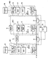
- the figure refers to a one-chip microcomputer system the three synchronously operated processors or central processing units 1,2,3, which are also known as computers or, because of their Function, referred to as processor cores. Any processor a bus system 4,5,6 is assigned.
- the central units 1,2,3 are connected to a synchronous clock supply cl (common clock), which is designed redundantly.
- the central unit 1 or the processor core 1 is by a Read-only memory 7 (ROM 1), by a read-write memory 8 (RAM 1), by an input and output unit 9 to a complete data processing system or microcomputer MC1 added.
- ROM 1 Read-only memory 7
- RAM 1 read-write memory 8
- input and output unit 9 to a complete data processing system or microcomputer MC1 added.
- the necessary peripheral components are symbolized by an external block 10.
- the peripheral components include the power supply, the supply of the input signals (e.g. the sensor signals in a vehicle control system) and the actuator or Valve control etc. using the output data or signals of the data processing systems.
- a second, incomplete data processing system or Microcomputer MC2 in which the central unit 2 is housed is only included in the exemplary embodiment shown Storage locations for test data or for the redundancy function. Inside the microcomputer are shown symbolically MC2 read-only memory locations 12 for parity monitoring (Parity ROM) and memory locations 13 for the Redundancy data in the read / write area (parity ROM). The associated test data or redundancy generators are the better clarity because not shown.
- Embodiment now consists in the fact that described system known from DE 195 29 434 A1 another complete data processing system, namely by a microcomputer MC3, which also with the incomplete microcomputer MC2 and also with the microcomputer MC1 interacts, is expanded.
- the additional microcomputer system (MC3) in particular storing the fixed value and read / write data, can, however, on the second microcomputer system MC2 and also be transferred to the first system MC1, because the overall system for ensuring the redundancy function in total only twice the storage capacity, plus some memory locations for the redundancy information, compared to a non-redundant, the same program processing system needed.
- the storage capacity The three data processing systems MC1, MC2, MC3 can be distributed so that if one system fails the remaining systems have sufficient storage space, namely at least 100% plus the redundancy data.
- the two are Microcomputer systems MC1 and MC3 each with a storage capacity of 100% compared to that for a non-redundant System needed storage space while only a few in the MC2 microcomputer system There are places for the redundancy data.
- the third microcomputer system MC3 is with the (incomplete) Microcomputer MC2 also by bypass or a bypass unit 16 connected.
- This bypass has it same function as the bypass already described in detail 14 and therefore also enables the central units 2 and 3 the redundant processing of all input data.
- the MC3 microprocessor system contains a read-only memory 17 (ROM 2), a random access memory 18 (RAM 2), one Input and output unit 19 and peripheral components 20 (Periphery 2).
- ROM 2 read-only memory
- RAM 2 random access memory
- Periphery 2 peripheral components 20
- MC1 and MC3 are in the illustrated embodiment complete microcomputers, for which, however, as explained earlier, a reduced storage capacity enough.
- the microcomputer MC3 has the same structure and the same components as the MC1 microcomputer. consequently are also in the microprocessor system according to the invention Input and output units 9.19 and the peripheral components 20, 21, to which the power supply, the sensor signal input and the actuator control count twice available.
- the output signals or data processing results of the third microcomputers MC3 are using a comparator 22 for agreement with the results or output signals of the microcomputer MC2 or the central unit 2 and in the same way with the aid of the comparator 23 Agreement with the results of the MC1 or the central unit 1 checked.
- This is not only an error detection, but also an identification of the system, in the fault is possible.
- a utilization of the data processing results is therefore during the limp home function too permissible for safety-critical control systems because a redundant one even if an error occurs Data processing is guaranteed.
- the system according to the invention can be compared with realize low manufacturing costs. In principle, it is enough - Compared to the known system, which does not have an emergency run allows - adding a processor core and increasing double the storage capacity. A classic one Solution with an emergency function would be at least three times Require memory overhead; this is a crucial advantage because the cost of the overall system largely depends on the Size of the main memory (read-only memory and read-write memory) be determined.
Landscapes
- Engineering & Computer Science (AREA)
- Mechanical Engineering (AREA)
- Automation & Control Theory (AREA)
- Transportation (AREA)
- Human Computer Interaction (AREA)
- Physics & Mathematics (AREA)
- General Physics & Mathematics (AREA)
- Hardware Redundancy (AREA)
- Safety Devices In Control Systems (AREA)
Abstract
Claims (7)
- Système de microprocesseur pour régulations critiques en ce qui concerne la sécurité, à traitement de données redondant, comprenant plusieurs unités centrales (CPU), qui sont reliées par l'intermédiaire de systèmes de bus séparés à des mémoires mortes et des mémoires vives contenant également des emplacements de mémoire pour des données de vérification, à des unités d'entrée et de sortie, et à des comparateurs vérifiant les données de sortie ou signaux de sortie des unités centrales en ce qui concerne une concordance, et qui exécutent le même programme, les unités centrales communiquant entre elles par l'intermédiaire des systèmes de bus et les systèmes de bus étant reliés entre eux au moyen de dérivations qui permettent aux unités centrales une lecture et un traitement communs des données se présentant, y compris les données de vérification et des instructions, caractérisé en ce qu'il est prévu trois unités centrales (1, 2, 3) qui sont étendues au moyen d'unités périphériques (10, 20) redondantes pour donner deux circuits de signaux de régulation complets et sont connectées ensemble d'une manière telle que les trois unités centrales (1, 2, 3) forment, en commun avec les mémoires (7, 8, 12, 13, 17, 18), avec les unités d'introduction et de délivrance (9, 19) et avec les unités périphériques (10, 20), en tout deux systèmes de traitement de données complets et un système de traitement de données incomplet, et en ce qu'en cas de défaillance d'une unité centrale (1, 2, 3) et/ou de composants associés, il est prévu qu'au moyen d'une décision à la majorité dans un étage d'identification (24), l'unité centrale défectueuse est identifiée et une fonction de secours est entretenue, et que, dans la fonction de secours, le traitement de données redondant et la comparaison des résultats de traitement de données en ce qui concerne une concordance sont maintenus et une non concordance est signalée, tandis qu'une délivrance de signaux de sortie et de signaux de commande, y compris du système défectueux ou de l'unité centrale défectueuse ou en fonction de celui-ci ou celle-ci, est empêchée.
- Système de microprocesseur suivant la revendication 1, caractérisé en ce que les trois unités centrales (1, 2, 3) sont pourvues chacune d'un système de bus (4, 5, 6) et en ce que, pour la mémoire morte (7, 12, 17) et pour la mémoire vive (8, 13, 18), c'est chaque fois au moins la capacité double, augmentée de quelques emplacements de mémoire pour les données de redondance, qui est disponible en comparaison de la capacité de mémoire nécessaire pour un système non redondant, tandis qu'au moyen des dérivations (14, 16), il existe une liaison entre toutes les unités centrales (1, 2, 3) et les emplacements de mémoire dans la mémoire vive et vers toutes les unités d'introduction et de délivrance (9, 10).
- Système de microprocesseur suivant la revendication 1 ou 2, caractérisé en ce que les trois systèmes de traitement de données comprennent chacun au moins une unité centrale (1, 2, 3) et un système de bus (4, 5, 6), ainsi qu'une mémoire morte et une mémoire vive (7, 17 ; 8, 18) et/ou des mémoires d'information de redondance (12, 13), les emplacements de mémoire étant répartis sur les différents systèmes de traitement de données d'une manière telle que, lors de l'apparition d'un défaut et d'un passage à la fonction de secours, les systèmes intacts contiennent suffisamment d'emplacements de mémoire pour le traitement de données complet et pour les informations de redondance et exécutent le programme complet.
- Système de microprocesseur suivant une ou plusieurs des revendications 1 à 3, caractérisé en ce que les résultats de traitement de données ou les signaux de sortie de deux unités centrales (1, 2, 3) peuvent chaque fois être envoyés aux comparateurs (15, 22, 23).
- Système de microprocesseur suivant une ou plusieurs des revendications 1 à 4, caractérisé en ce qu'au moins les unités centrales (1, 2, 3) sont disposées, avec les systèmes de bus (4, 5, 6), les mémoires (7, 8, 12, 13, 17, 18), les dérivations (14, 16), les unités d'introduction et de délivrance (9, 19), des comparateurs (15, 22, 23) et des étages d'identification (24), sur une puce commune.
- Système de microprocesseur suivant une ou plusieurs des revendications 1 à 5, caractérisé en ce que celui-ci est conçu pour plusieurs systèmes de régulation de véhicule automobile, tels que frein-par-fil, ABS, ASR, ASMS, etc., ou une combinaison de tels système, et en ce que la fonction de secours détecte le maintien du fonctionnement de tous les systèmes de régulation.
- Système de microprocesseur suivant une ou plusieurs des revendications 1 à 5, caractérisé en ce que celui-ci est conçu pour plusieurs systèmes de régulation de véhicule automobile ou pour une combinaison de tels systèmes et en ce que la fonction de secours est limitée au maintien du fonctionnement de fonctions de régulation sélectionnées, par exemple de fonctions particulièrement critiques en ce qui concerne la sécurité.
Applications Claiming Priority (3)
| Application Number | Priority Date | Filing Date | Title |
|---|---|---|---|
| DE19716197A DE19716197A1 (de) | 1997-04-18 | 1997-04-18 | Mikroprozessorsystem für sicherheitskritische Regelungen |
| DE19716197 | 1997-04-18 | ||
| PCT/EP1998/000921 WO1998048326A1 (fr) | 1997-04-18 | 1998-02-18 | Systeme de microprocesseur pour systemes de regulation a securite critique |
Publications (2)
| Publication Number | Publication Date |
|---|---|
| EP0976012A1 EP0976012A1 (fr) | 2000-02-02 |
| EP0976012B1 true EP0976012B1 (fr) | 2002-07-24 |
Family
ID=7826876
Family Applications (1)
| Application Number | Title | Priority Date | Filing Date |
|---|---|---|---|
| EP98913559A Expired - Lifetime EP0976012B1 (fr) | 1997-04-18 | 1998-02-18 | Systeme de microprocesseur pour systemes de regulation a securite critique |
Country Status (5)
| Country | Link |
|---|---|
| US (1) | US6823251B1 (fr) |
| EP (1) | EP0976012B1 (fr) |
| JP (1) | JP2001521661A (fr) |
| DE (2) | DE19716197A1 (fr) |
| WO (1) | WO1998048326A1 (fr) |
Cited By (1)
| Publication number | Priority date | Publication date | Assignee | Title |
|---|---|---|---|---|
| EP2099667B2 (fr) † | 2006-11-30 | 2016-06-29 | Continental Teves AG & Co. oHG | Procede pour garantir ou maintenir la fonction d'un systeme global complexe critique pour la securite |
Families Citing this family (54)
| Publication number | Priority date | Publication date | Assignee | Title |
|---|---|---|---|---|
| NL1016457C2 (nl) * | 2000-10-23 | 2002-04-24 | Skf Eng & Res Centre Bv | Reserve-remsysteem en -werkwijze voor elektronisch bestuurd (drive-by-wire) voertuig. |
| DE10053820A1 (de) * | 2000-10-30 | 2002-05-29 | Pilz Gmbh & Co | Elektronisches Sicherheitsschaltgerät |
| DE10291055D2 (de) * | 2001-03-15 | 2004-04-15 | Bosch Gmbh Robert | Verfahren zur Ansteuerung einer Komponente eines verteilten sicherheitsrelevanten Systems |
| DE10291112D2 (de) | 2001-03-15 | 2004-04-15 | Bosch Gmbh Robert | Verfahren zur Ansteuerung einer Komponente eines verteilten sicherheitsrelevanten Systems |
| DE10124027A1 (de) * | 2001-05-16 | 2002-11-21 | Continental Teves Ag & Co Ohg | Verfahren,Mikroprozessorsystem für sicherheitskritische Regelungen und dessen Verwendung |
| US20030023887A1 (en) * | 2001-07-30 | 2003-01-30 | Maciorowski David R. | Computer system with backup management for handling embedded processor failure |
| JP4319547B2 (ja) * | 2001-12-11 | 2009-08-26 | コンティネンタル・テーベス・アクチエンゲゼルシヤフト・ウント・コンパニー・オッフェネ・ハンデルスゲゼルシヤフト | マルチコア型冗長制御コンピュータシステム、自動車における安全上重要な用途のためのコンピュータネットワーク並びにその使用 |
| GB2395241B (en) * | 2002-11-12 | 2004-12-29 | Knorr Bremse Systeme | Electronic control apparatus for a vehicle |
| DE112004001836D2 (de) * | 2003-10-08 | 2006-08-24 | Continental Teves Ag & Co Ohg | Integriertes Mikroprozessorsystem für sicherheitskritische Regelungen |
| DE10360881A1 (de) * | 2003-12-23 | 2005-07-28 | Knorr-Bremse Systeme für Nutzfahrzeuge GmbH | Integration einer Luftfederungselektronik in ein elektronisches Luftaufbereitungssystem |
| DE10360875B4 (de) * | 2003-12-23 | 2008-03-27 | Knorr-Bremse Systeme für Nutzfahrzeuge GmbH | Integration einer Luftfederungselektronik in ein elektronisches Bremssystem |
| US7467035B2 (en) * | 2004-05-18 | 2008-12-16 | Haldex Brake Products Ltd. | Vehicle control system with redundant storage of vehicle control parameters |
| DE102005010820C5 (de) * | 2005-03-07 | 2014-06-26 | Phoenix Contact Gmbh & Co. Kg | Kopplung von sicheren Feldbussystemen |
| DE102006008958A1 (de) * | 2005-03-10 | 2006-09-28 | Continental Teves Ag & Co. Ohg | Elektronisches Kraftfahrzeugbremsensteuergerät |
| JP5389440B2 (ja) * | 2005-08-11 | 2014-01-15 | コンチネンタル・テベス・アーゲー・ウント・コンパニー・オーハーゲー | 少なくとも部分的に安全上重大なプロセスの制御または調節用マイクロプロセッサシステム |
| JP2009505188A (ja) * | 2005-08-11 | 2009-02-05 | コンティネンタル・テーベス・アクチエンゲゼルシヤフト・ウント・コンパニー・オッフェネ・ハンデルスゲゼルシヤフト | 少なくとも部分的に安全上重大なプロセスの制御または調節用マイクロプロセッサシステム |
| DE102005046373B4 (de) * | 2005-09-28 | 2007-12-13 | Siemens Ag | Kommunikationssystem für ein technisches Gerät, insbesondere für ein Kraftfahrzeug |
| DE102006002824B4 (de) * | 2006-01-19 | 2008-10-09 | Phoenix Contact Gmbh & Co. Kg | Verfahren und Vorrichtung zur Umwandlung mehrkanalig vorliegender Nachrichten in eine einkanalige sichere Nachricht |
| DE102006046216B3 (de) * | 2006-09-29 | 2008-05-29 | Siemens Ag | Verfahren und Vorrichtung zum Betreiben eines Kraftfahrzeugs |
| DE102006053617A1 (de) * | 2006-11-14 | 2008-05-15 | Siemens Ag | System zur Aktorsteuerung, insbesondere Bremssystem |
| DE102006054124B4 (de) | 2006-11-15 | 2009-05-28 | Phoenix Contact Gmbh & Co. Kg | Verfahren und System zur sicheren Datenübertragung |
| DE102006056420B4 (de) * | 2006-11-28 | 2012-11-29 | Wago Verwaltungsgesellschaft Mbh | Sicherheitsmodul und Automatisierungssystem |
| US7634350B2 (en) * | 2006-11-30 | 2009-12-15 | Caterpillar Inc. | Automatic configuration for a secondary engine electronic governor |
| ATE520079T1 (de) * | 2007-05-25 | 2011-08-15 | Freescale Semiconductor Inc | Datenverarbeitungssystem, datenverarbeitungsverfahren und vorrichtung |
| EP2008903B1 (fr) * | 2007-06-25 | 2012-02-29 | Magneti Marelli S.p.A. | Agencement de circuit de secours pour fonctions de compartiment passager et de caisse |
| US9207661B2 (en) * | 2007-07-20 | 2015-12-08 | GM Global Technology Operations LLC | Dual core architecture of a control module of an engine |
| ATE485203T1 (de) * | 2007-08-17 | 2010-11-15 | Magneti Marelli Spa | Verbesserte limp-home-schaltungsanordnung für insassenraum- und karosseriefunktionen |
| DE102007046706A1 (de) * | 2007-09-28 | 2009-04-16 | Autoliv Development Ab | Steuervorrichtung für Fahrzeuge |
| DE102007062974B4 (de) * | 2007-12-21 | 2010-04-08 | Phoenix Contact Gmbh & Co. Kg | Signalverarbeitungsvorrichtung |
| US8010846B1 (en) * | 2008-04-30 | 2011-08-30 | Honeywell International Inc. | Scalable self-checking processing platform including processors executing both coupled and uncoupled applications within a frame |
| IT1391785B1 (it) * | 2008-11-21 | 2012-01-27 | St Microelectronics Srl | Sistema elettronico per il rilevamento di un guasto |
| US8185773B2 (en) * | 2008-12-31 | 2012-05-22 | Stmicroelectronics S.R.L. | Processor system employing a signal acquisition managing device and signal acquisition managing device |
| US8478478B2 (en) * | 2009-07-31 | 2013-07-02 | Stmicroelectronics S.R.L. | Processor system and fault managing unit thereof |
| NL1037275C2 (nl) * | 2009-09-11 | 2011-03-14 | Advanced Public Transp Systems B V | Stuurinrichting voor een vooraf gedefinieerd traject verplaatsbaar voertuig, automatisch gestuurd en via tenminste een eerste as , alsmede een voertuig voorzien van een dergelijke stuurinrichting. |
| JP5537447B2 (ja) * | 2011-01-19 | 2014-07-02 | 株式会社日立製作所 | 多重化制御システム、多重化制御方法、および、多重化制御プログラム |
| DE102011005766A1 (de) * | 2011-03-18 | 2012-09-20 | Zf Friedrichshafen Ag | Steuergerät für ein Kraftfahrzeug |
| DE102011101358A1 (de) * | 2011-05-12 | 2012-11-15 | Audi Ag | Kraftwagen mit zwei elektronischen Komponenten zum Bereitstellen einer Funktion des Kraftwagens und zugehöriges Betriebsverfahren |
| DE102011084569B4 (de) * | 2011-10-14 | 2019-02-21 | Continental Automotive Gmbh | Verfahren zum Betreiben eines informationstechnischen Systems und informationstechnisches System |
| DE102012210106A1 (de) * | 2012-06-15 | 2013-12-19 | Robert Bosch Gmbh | Sensoranordnung für eine Elektrik/Elektronik-Architektur und zugehörige Elektrik/Elektronik-Architektur für ein Fahrzeug |
| DE102012212304A1 (de) | 2012-07-13 | 2014-01-16 | Siemens Aktiengesellschaft | Anordnung mit einem Mikroprozessorsystem |
| JP6118043B2 (ja) * | 2012-07-18 | 2017-04-19 | 矢崎総業株式会社 | 表示装置 |
| DE102013000360A1 (de) | 2013-01-10 | 2014-07-10 | Audi Ag | Verfahren für die Regelung eines Vertikalregelsystems eines Fahrzeugs |
| US9740178B2 (en) * | 2013-03-14 | 2017-08-22 | GM Global Technology Operations LLC | Primary controller designation in fault tolerant systems |
| DE102013012497A1 (de) | 2013-07-26 | 2015-01-29 | Wabco Gmbh | Verfahren und elektronische Schaltungsanordnung zur redundanten Signalverarbeitung einer sicherheitsrelevanten Anwendung, Kraftfahrzeugbremssystem und Kraftfahrzeug damit sowie Verwendung einer derartigen elektronischen Schaltungsanordnung |
| WO2015168768A1 (fr) * | 2014-05-05 | 2015-11-12 | Sanuvox Technologies Inc. | Système de décontamination de pièce, procédé et organe commande |
| DE102014217321A1 (de) * | 2014-08-29 | 2016-03-03 | Continental Teves Ag & Co. Ohg | Mikrocontrollersystem und Verfahren für sicherheitskritische Kraftfahrzeugsysteme sowie deren Verwendung |
| DE102016112332B4 (de) * | 2016-07-06 | 2021-09-02 | Robert Bosch Gmbh | Verfahren und vorrichtung zum überwachen eines reglerblocks zum ansteuern eines stellantriebs, insbesondere eines stellantriebs eines lenksystems |
| DE102016116751A1 (de) | 2016-09-07 | 2018-03-08 | Xtronic Gmbh | Bussystem zum Realisieren einer elektronischen Steuerung oder einer elektrischen Regelung sowie Fahrzeug |
| JP6515208B2 (ja) * | 2017-03-31 | 2019-05-15 | 本田技研工業株式会社 | 汎用エンジンの制御装置 |
| DE102017217100B4 (de) * | 2017-09-26 | 2022-11-10 | Robert Bosch Gmbh | Verfahren und Vorrichtung zum Betreiben eines Stellmotors eines Lenksystems |
| DE102017218274A1 (de) * | 2017-10-12 | 2019-04-18 | Volkswagen Aktiengesellschaft | Lenkungssteuersystem für ein Lenksystem eines Kraftfahrzeuges sowie Verfahren zum Betreiben eines Lenkungssteuersystems |
| US20190299955A1 (en) * | 2018-03-29 | 2019-10-03 | Veoneer Us Inc. | Autonomous vehicle brake system |
| DE102023117791A1 (de) * | 2023-07-06 | 2025-01-09 | HELLA GmbH & Co. KGaA | Steuergerät für ein Kontrollsystem eines Kraftfahrzeugs, Kontrollsystem für ein Kraftfahrzeug und Verfahren zum Betrieb eines Kontrollsystems |
| JP2025034218A (ja) * | 2023-08-30 | 2025-03-13 | 株式会社デンソー | 車両用電子制御装置及び方法 |
Family Cites Families (26)
| Publication number | Priority date | Publication date | Assignee | Title |
|---|---|---|---|---|
| US3665173A (en) * | 1968-09-03 | 1972-05-23 | Ibm | Triple modular redundancy/sparing |
| DE3024370C2 (de) * | 1980-06-27 | 1987-01-02 | Siemens AG, 1000 Berlin und 8000 München | Redundantes Steuersystem |
| DE3225455C2 (de) * | 1982-07-07 | 1986-07-17 | Siemens AG, 1000 Berlin und 8000 München | Verfahren zum sicheren Betrieb eines redundanten Steuersystems |
| DE3234637A1 (de) | 1982-09-18 | 1984-03-22 | Alfred Teves Gmbh, 6000 Frankfurt | Verfahren und schaltungsanordnung zur steuerung einer bremsschlupfregelanlage |
| GB2237904B (en) * | 1984-02-28 | 1991-10-02 | Lucas Ind Plc | Digital control system |
| US4672530A (en) | 1984-12-17 | 1987-06-09 | Combustion Engineering, Inc. | Distributed control with universal program |
| US4726024A (en) * | 1986-03-31 | 1988-02-16 | Mieczyslaw Mirowski | Fail safe architecture for a computer system |
| US4967347A (en) * | 1986-04-03 | 1990-10-30 | Bh-F (Triplex) Inc. | Multiple-redundant fault detection system and related method for its use |
| FR2632748B1 (fr) * | 1988-06-14 | 1994-04-29 | Alsthom | Dispositif de traitement de donnees et de commande |
| JPH01320564A (ja) * | 1988-06-23 | 1989-12-26 | Hitachi Ltd | 並列処理装置 |
| DE3825280A1 (de) * | 1988-07-26 | 1990-02-01 | Bayerische Motoren Werke Ag | Steuersystem fuer stelleinrichtungen eines kraftfahrzeugs |
| US5086499A (en) * | 1989-05-23 | 1992-02-04 | Aeg Westinghouse Transportation Systems, Inc. | Computer network for real time control with automatic fault identification and by-pass |
| US5317752A (en) * | 1989-12-22 | 1994-05-31 | Tandem Computers Incorporated | Fault-tolerant computer system with auto-restart after power-fall |
| US5295258A (en) * | 1989-12-22 | 1994-03-15 | Tandem Computers Incorporated | Fault-tolerant computer system with online recovery and reintegration of redundant components |
| JPH04133601A (ja) | 1990-09-21 | 1992-05-07 | Toshiba Corp | 保安機能付自動運転制御装置 |
| DE4122016A1 (de) * | 1991-07-03 | 1993-01-21 | Hella Kg Hueck & Co | Antiblockierregelsystem |
| DE4136338A1 (de) * | 1991-11-05 | 1993-05-06 | Robert Bosch Gmbh, 7000 Stuttgart, De | Verfahren und vorrichtung zur fehlerbehandlung in elektronischen steuergeraeten |
| US5458404A (en) * | 1991-11-12 | 1995-10-17 | Itt Automotive Europe Gmbh | Redundant wheel sensor signal processing in both controller and monitoring circuits |
| US5742760A (en) * | 1992-05-12 | 1998-04-21 | Compaq Computer Corporation | Network packet switch using shared memory for repeating and bridging packets at media rate |
| GB9217728D0 (en) * | 1992-08-20 | 1992-09-30 | Texas Instruments Ltd | Method of testing interconnections between integrated circuits in a circuit |
| DE4341082A1 (de) * | 1993-12-02 | 1995-06-08 | Teves Gmbh Alfred | Schaltungsanordnung für sicherheitskritische Regelungssysteme |
| DE4439060A1 (de) * | 1994-11-02 | 1996-05-09 | Teves Gmbh Alfred | Mikroprozessoranordnung für ein Fahrzeug-Regelungssystem |
| DE19509150C2 (de) * | 1995-03-14 | 2003-03-27 | Continental Teves Ag & Co Ohg | Verfahren zum Steuern und Regeln von Fahrzeug-Bremsanlagen sowie Fahrzeug-Bremsanlage |
| DE19529434B4 (de) * | 1995-08-10 | 2009-09-17 | Continental Teves Ag & Co. Ohg | Microprozessorsystem für sicherheitskritische Regelungen |
| DE19631309A1 (de) * | 1996-08-02 | 1998-02-05 | Teves Gmbh Alfred | Mikroprozessoranordnung für ein Fahrzeug-Regelungssystem |
| US6128687A (en) * | 1997-07-23 | 2000-10-03 | Texas Instrumenets Incorporated | Fast fault detection circuitry for a microprocessor |
-
1997
- 1997-04-18 DE DE19716197A patent/DE19716197A1/de not_active Withdrawn
-
1998
- 1998-02-18 WO PCT/EP1998/000921 patent/WO1998048326A1/fr not_active Ceased
- 1998-02-18 JP JP54478898A patent/JP2001521661A/ja active Pending
- 1998-02-18 DE DE59804897T patent/DE59804897D1/de not_active Expired - Lifetime
- 1998-02-18 EP EP98913559A patent/EP0976012B1/fr not_active Expired - Lifetime
- 1998-02-18 US US09/403,115 patent/US6823251B1/en not_active Expired - Fee Related
Cited By (1)
| Publication number | Priority date | Publication date | Assignee | Title |
|---|---|---|---|---|
| EP2099667B2 (fr) † | 2006-11-30 | 2016-06-29 | Continental Teves AG & Co. oHG | Procede pour garantir ou maintenir la fonction d'un systeme global complexe critique pour la securite |
Also Published As
| Publication number | Publication date |
|---|---|
| JP2001521661A (ja) | 2001-11-06 |
| US6823251B1 (en) | 2004-11-23 |
| DE19716197A1 (de) | 1998-10-22 |
| EP0976012A1 (fr) | 2000-02-02 |
| DE59804897D1 (de) | 2002-08-29 |
| WO1998048326A1 (fr) | 1998-10-29 |
Similar Documents
| Publication | Publication Date | Title |
|---|---|---|
| EP0976012B1 (fr) | Systeme de microprocesseur pour systemes de regulation a securite critique | |
| EP0981783B1 (fr) | Systeme de microprocesseur pour systemes de regulation de vehicules automobiles | |
| EP0979189B1 (fr) | Dispositif de commutation pour systeme de regulation pour vehicule a moteur | |
| EP0731937B1 (fr) | Circuit pour systeme de reglage a securite critique | |
| EP1673667B1 (fr) | Systeme de microprocesseur integre pour regulations critiques en termes de securite | |
| WO1997006487A1 (fr) | Systeme a microprocesseurs pour dispositifs de regulation critiques sur le plan securite | |
| DE19650104B4 (de) | Elektronische Steuervorrichtung für ein Kraftfahrzeug | |
| EP1456720B1 (fr) | Systeme informatique de commande redondant a plusieurs noyaux, reseau informatique pour des applications critiques en matiere de securite dans des vehicules automobiles et son utilisation | |
| EP1046088B1 (fr) | Dispositif numerique electronique | |
| EP1625061B1 (fr) | Systeme de freinage pour des vehicules, notamment des vehicules utilitaires, comprenant au moins deux circuits de commande de freinage electroniques distincts. | |
| DE3429941C2 (de) | Kommunikationssystem für Fahrzeugkörper | |
| DE69925000T2 (de) | Fehlertolerantes elektronisches bremssystem | |
| EP0789655A1 (fr) | Groupement de microprocesseurs pour systeme de regulation destine a un vehicule | |
| DE102015003194A1 (de) | Verfahren und Vorrichtung zum Handhaben von sicherheitskritischen Fehlern | |
| DE102005037246A1 (de) | Verfahren und Vorrichtung zur Steuerung eines Rechnersystems mit wenigstens zwei Ausführungseinheiten und einer Vergleichseinheit | |
| DE2225841C3 (de) | Verfahren und Anordnung zur systematischen Fehlerprüfung eines monolithischen Halbleiterspeichers | |
| EP0712360B1 (fr) | Circuit de regulation de systemes de freinage a antiblocage automatique et/ou a systeme anti-patinage a l'acceleration | |
| DE19509150C2 (de) | Verfahren zum Steuern und Regeln von Fahrzeug-Bremsanlagen sowie Fahrzeug-Bremsanlage | |
| EP1428120A2 (fr) | Procede et systeme a microprocesseurs destines a des regulations critiques pour la securite et utilisation de ce dernier | |
| EP1053153B1 (fr) | Procede pour le traitement d'erreurs dans un systeme de freinage electronique et dispositif associe | |
| EP1588380B1 (fr) | Procede de reconnaissance et/ou de correction d'erreurs d'acces a la memoire et circuit electronique destine a effectuer le procede | |
| DE10302456A1 (de) | Vorrichtung für sicherheitskritische Anwendungen und sichere Elektronik-Architektur | |
| DE102007046706A1 (de) | Steuervorrichtung für Fahrzeuge | |
| DE69911255T2 (de) | Mikroprozessormodul mit abstimmungseinrichtung zur rückstellung und verfahren dazu | |
| DE1966991A1 (de) | Ausfallgesicherte datenverarbeitungsanlage |
Legal Events
| Date | Code | Title | Description |
|---|---|---|---|
| PUAI | Public reference made under article 153(3) epc to a published international application that has entered the european phase |
Free format text: ORIGINAL CODE: 0009012 |
|
| 17P | Request for examination filed |
Effective date: 19991118 |
|
| AK | Designated contracting states |
Kind code of ref document: A1 Designated state(s): DE FR GB |
|
| 17Q | First examination report despatched |
Effective date: 20000728 |
|
| GRAG | Despatch of communication of intention to grant |
Free format text: ORIGINAL CODE: EPIDOS AGRA |
|
| GRAG | Despatch of communication of intention to grant |
Free format text: ORIGINAL CODE: EPIDOS AGRA |
|
| GRAH | Despatch of communication of intention to grant a patent |
Free format text: ORIGINAL CODE: EPIDOS IGRA |
|
| GRAH | Despatch of communication of intention to grant a patent |
Free format text: ORIGINAL CODE: EPIDOS IGRA |
|
| GRAA | (expected) grant |
Free format text: ORIGINAL CODE: 0009210 |
|
| AK | Designated contracting states |
Kind code of ref document: B1 Designated state(s): DE FR GB |
|
| REG | Reference to a national code |
Ref country code: GB Ref legal event code: FG4D Free format text: NOT ENGLISH |
|
| GBT | Gb: translation of ep patent filed (gb section 77(6)(a)/1977) |
Effective date: 20020724 |
|
| REF | Corresponds to: |
Ref document number: 59804897 Country of ref document: DE Date of ref document: 20020829 |
|
| ET | Fr: translation filed | ||
| PLBE | No opposition filed within time limit |
Free format text: ORIGINAL CODE: 0009261 |
|
| STAA | Information on the status of an ep patent application or granted ep patent |
Free format text: STATUS: NO OPPOSITION FILED WITHIN TIME LIMIT |
|
| 26N | No opposition filed |
Effective date: 20030425 |
|
| PGFP | Annual fee paid to national office [announced via postgrant information from national office to epo] |
Ref country code: FR Payment date: 20130314 Year of fee payment: 16 Ref country code: DE Payment date: 20130228 Year of fee payment: 16 Ref country code: GB Payment date: 20130221 Year of fee payment: 16 |
|
| REG | Reference to a national code |
Ref country code: DE Ref legal event code: R119 Ref document number: 59804897 Country of ref document: DE |
|
| GBPC | Gb: european patent ceased through non-payment of renewal fee |
Effective date: 20140218 |
|
| REG | Reference to a national code |
Ref country code: FR Ref legal event code: ST Effective date: 20141031 |
|
| REG | Reference to a national code |
Ref country code: DE Ref legal event code: R119 Ref document number: 59804897 Country of ref document: DE Effective date: 20140902 |
|
| PG25 | Lapsed in a contracting state [announced via postgrant information from national office to epo] |
Ref country code: DE Free format text: LAPSE BECAUSE OF NON-PAYMENT OF DUE FEES Effective date: 20140902 Ref country code: FR Free format text: LAPSE BECAUSE OF NON-PAYMENT OF DUE FEES Effective date: 20140228 Ref country code: GB Free format text: LAPSE BECAUSE OF NON-PAYMENT OF DUE FEES Effective date: 20140218 |