EP0976510A2 - Dispositif de coupe rotative - Google Patents
Dispositif de coupe rotative Download PDFInfo
- Publication number
- EP0976510A2 EP0976510A2 EP99114200A EP99114200A EP0976510A2 EP 0976510 A2 EP0976510 A2 EP 0976510A2 EP 99114200 A EP99114200 A EP 99114200A EP 99114200 A EP99114200 A EP 99114200A EP 0976510 A2 EP0976510 A2 EP 0976510A2
- Authority
- EP
- European Patent Office
- Prior art keywords
- cutting
- support ring
- force
- anvil
- section
- Prior art date
- Legal status (The legal status is an assumption and is not a legal conclusion. Google has not performed a legal analysis and makes no representation as to the accuracy of the status listed.)
- Granted
Links
Images

Classifications
-
- B—PERFORMING OPERATIONS; TRANSPORTING
- B26—HAND CUTTING TOOLS; CUTTING; SEVERING
- B26F—PERFORATING; PUNCHING; CUTTING-OUT; STAMPING-OUT; SEVERING BY MEANS OTHER THAN CUTTING
- B26F1/00—Perforating; Punching; Cutting-out; Stamping-out; Apparatus therefor
- B26F1/38—Cutting-out; Stamping-out
- B26F1/44—Cutters therefor; Dies therefor
-
- B—PERFORMING OPERATIONS; TRANSPORTING
- B26—HAND CUTTING TOOLS; CUTTING; SEVERING
- B26D—CUTTING; DETAILS COMMON TO MACHINES FOR PERFORATING, PUNCHING, CUTTING-OUT, STAMPING-OUT OR SEVERING
- B26D7/00—Details of apparatus for cutting, cutting-out, stamping-out, punching, perforating, or severing by means other than cutting
- B26D7/26—Means for mounting or adjusting the cutting member; Means for adjusting the stroke of the cutting member
- B26D7/2628—Means for adjusting the position of the cutting member
-
- B—PERFORMING OPERATIONS; TRANSPORTING
- B26—HAND CUTTING TOOLS; CUTTING; SEVERING
- B26D—CUTTING; DETAILS COMMON TO MACHINES FOR PERFORATING, PUNCHING, CUTTING-OUT, STAMPING-OUT OR SEVERING
- B26D7/00—Details of apparatus for cutting, cutting-out, stamping-out, punching, perforating, or severing by means other than cutting
- B26D7/26—Means for mounting or adjusting the cutting member; Means for adjusting the stroke of the cutting member
- B26D7/2628—Means for adjusting the position of the cutting member
- B26D7/265—Journals, bearings or supports for positioning rollers or cylinders relatively to each other
-
- B—PERFORMING OPERATIONS; TRANSPORTING
- B26—HAND CUTTING TOOLS; CUTTING; SEVERING
- B26F—PERFORATING; PUNCHING; CUTTING-OUT; STAMPING-OUT; SEVERING BY MEANS OTHER THAN CUTTING
- B26F1/00—Perforating; Punching; Cutting-out; Stamping-out; Apparatus therefor
- B26F1/38—Cutting-out; Stamping-out
- B26F1/384—Cutting-out; Stamping-out using rotating drums
-
- B—PERFORMING OPERATIONS; TRANSPORTING
- B26—HAND CUTTING TOOLS; CUTTING; SEVERING
- B26F—PERFORATING; PUNCHING; CUTTING-OUT; STAMPING-OUT; SEVERING BY MEANS OTHER THAN CUTTING
- B26F1/00—Perforating; Punching; Cutting-out; Stamping-out; Apparatus therefor
- B26F1/38—Cutting-out; Stamping-out
- B26F1/44—Cutters therefor; Dies therefor
- B26F2001/4409—Cutters therefor; Dies therefor having die balancing or compensating means
-
- Y—GENERAL TAGGING OF NEW TECHNOLOGICAL DEVELOPMENTS; GENERAL TAGGING OF CROSS-SECTIONAL TECHNOLOGIES SPANNING OVER SEVERAL SECTIONS OF THE IPC; TECHNICAL SUBJECTS COVERED BY FORMER USPC CROSS-REFERENCE ART COLLECTIONS [XRACs] AND DIGESTS
- Y10—TECHNICAL SUBJECTS COVERED BY FORMER USPC
- Y10T—TECHNICAL SUBJECTS COVERED BY FORMER US CLASSIFICATION
- Y10T83/00—Cutting
- Y10T83/465—Cutting motion of tool has component in direction of moving work
- Y10T83/4766—Orbital motion of cutting blade
- Y10T83/4795—Rotary tool
- Y10T83/483—With cooperating rotary cutter or backup
- Y10T83/4833—Cooperating tool axes adjustable relative to each other
-
- Y—GENERAL TAGGING OF NEW TECHNOLOGICAL DEVELOPMENTS; GENERAL TAGGING OF CROSS-SECTIONAL TECHNOLOGIES SPANNING OVER SEVERAL SECTIONS OF THE IPC; TECHNICAL SUBJECTS COVERED BY FORMER USPC CROSS-REFERENCE ART COLLECTIONS [XRACs] AND DIGESTS
- Y10—TECHNICAL SUBJECTS COVERED BY FORMER USPC
- Y10T—TECHNICAL SUBJECTS COVERED BY FORMER US CLASSIFICATION
- Y10T83/00—Cutting
- Y10T83/465—Cutting motion of tool has component in direction of moving work
- Y10T83/4766—Orbital motion of cutting blade
- Y10T83/4795—Rotary tool
- Y10T83/483—With cooperating rotary cutter or backup
- Y10T83/4838—With anvil backup
- Y10T83/4841—With resilient anvil surface
-
- Y—GENERAL TAGGING OF NEW TECHNOLOGICAL DEVELOPMENTS; GENERAL TAGGING OF CROSS-SECTIONAL TECHNOLOGIES SPANNING OVER SEVERAL SECTIONS OF THE IPC; TECHNICAL SUBJECTS COVERED BY FORMER USPC CROSS-REFERENCE ART COLLECTIONS [XRACs] AND DIGESTS
- Y10—TECHNICAL SUBJECTS COVERED BY FORMER USPC
- Y10T—TECHNICAL SUBJECTS COVERED BY FORMER US CLASSIFICATION
- Y10T83/00—Cutting
- Y10T83/465—Cutting motion of tool has component in direction of moving work
- Y10T83/4766—Orbital motion of cutting blade
- Y10T83/4795—Rotary tool
- Y10T83/483—With cooperating rotary cutter or backup
- Y10T83/4844—Resiliently urged cutter or anvil member
-
- Y—GENERAL TAGGING OF NEW TECHNOLOGICAL DEVELOPMENTS; GENERAL TAGGING OF CROSS-SECTIONAL TECHNOLOGIES SPANNING OVER SEVERAL SECTIONS OF THE IPC; TECHNICAL SUBJECTS COVERED BY FORMER USPC CROSS-REFERENCE ART COLLECTIONS [XRACs] AND DIGESTS
- Y10—TECHNICAL SUBJECTS COVERED BY FORMER USPC
- Y10T—TECHNICAL SUBJECTS COVERED BY FORMER US CLASSIFICATION
- Y10T83/00—Cutting
- Y10T83/768—Rotatable disc tool pair or tool and carrier
- Y10T83/7809—Tool pair comprises rotatable tools
- Y10T83/7851—Tool pair comprises disc and cylindrical anvil
- Y10T83/7855—With adjustable means to urge tool elements together
Definitions
- Such cutting devices are from the prior art known.
- the usual procedure for these is that the cutting tool is fed so far to the anvil roller is that even with maximum cutting forces sufficient Cutting effect is given.
- the invention is therefore based on the object To improve the cutting device of the generic type in such a way that the cutting tool has the longest possible service life having.
- a particularly simple possibility of such a cross-sectional variation is when the support ring is in a Direction transverse to the radial direction and transverse to the azimuthal Direction has a varying shape.
- Such a shape variation can, for example, by introducing itself in this direction extending recesses in the support ring with an otherwise constant cross-section.
- Such recesses can expediently, for example from an outer edge, transverse to Recesses formed azimuthal direction his.
- Another alternative of the solution according to the invention provides before that the support ring has a homogeneous material elasticity and maintains an unchanged shape and that the reduction in Deformation of the support ring at the transition from maximum contact force thus taken into account for minimum tracking force is that the cutting edge sections effective with minimal contact force have a greater extent in the radial direction than the cutting edge sections where the contact force maximum and the cutting force is minimal.
- An advantageous way to fix the support ring on the cutting tool is to place the support ring on the Shrink on cutting tool and if necessary still additionally to be fixed positively.
- Support surfaces are arranged directly on the anvil roller, so that uniform machining of the supporting surfaces and the anvil surfaces is possible.
- the support surfaces can then be produced particularly easily, if they form part of the anvil surfaces, because in this case only a surface with the desired one Precision.
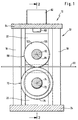
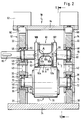
- Each of the bearing parts for example the bearing part 12 in Fig. 1, comprises two side beams 16 and 18, between which a lower bearing bracket 20 and an upper bearing bracket 22 are arranged.
- the upper bearing bracket 22 is between the side brackets 16 and 18 guided and in a direction 42 which is parallel to Extension of the side beams 16 and 18 runs in the direction of the lower bearing bracket 20 is arranged adjustable. Also the upper bearing bracket 22 has a bearing seat 46, in which an upper pivot bearing 48 is used.
- the upper bearing bracket 22 is a tool shaft 82 rotatably supported about an axis of rotation 84, where the tool shaft 82, for example, by the Bearing part 12 extends through and rotating on it Tool 80 opposite side over the bearing part 12 protruding drive stub 86, over which by means of a drive, for example a motor Rotary drive of the rotating tool 80 takes place.
- a drive for example a motor Rotary drive of the rotating tool 80 takes place.
- the rotating tool 80 is due to the arrangement of the upper one Pivot bearing 48 in the upper bearing supports 22 and their displaceability in direction 42 in the direction of the anvil roller 70 movable.
- the biasing devices 60 which on the act upper bearing bracket 22, is the rotating tool 80 so biased towards the anvil roller 70 that this as The whole acts on the anvil roll 70 with a prestressing force V.
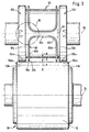
- the rotating cutting tool 80 now has to be cut one designated as a whole with 90 and between the rotating cutting tool 80 and the anvil roll 70 passed Material web 90 cutting 92, which of one, for example, cylindrical to the axis of rotation 84 Cutting surface area in the radial direction to the axis of rotation 84 with constant radial extension with respect to the axis of rotation survive.
- the cutting edge 92 comprises two extending in the azimuthal direction to the axis of rotation 84 Cutting leg 92a, which in transverse to this Cutting edges 92b pass over, which are then through a cross cutting edge 92c, which is approximately perpendicular to the azimuthal direction 96 and thus runs approximately parallel to the axis of rotation 84 are (Fig. 3).
- the cutting action of the cutting edge 92 now takes place, as in FIG. 3 represented by the interaction of an effective cutting section 92s, which has a corresponding anvil surface section 76s with minimal distance or almost touched it, by rotating the rotating Cutting tool 80 and co-rotation of the anvil roll 70 successive cutting sections 92s and Anvil surface portions 76s are in their operative position and interact cuttingly.
- the support takes place in each case via the support ring sections 104s and 106s on corresponding support surface sections 108s and 110s of the support surfaces 108 and 110 are seated, while rotating tool 80 opposite to the direction of rotation of the same successively arranged support ring sections 104s and 106s with opposite to the direction of rotation of the anvil roller 70 successively arranged support surface sections 108s and 110s cooperate.
- the respective support ring sections interacting with each other 104s, 106s and support surface sections 108s and 110s absorb a total of A, with which the rotating cutting tool 80 on the anvil roll 70 supports and which one of the biasing force V part of the same.
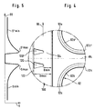
- the invention provides that elastic behavior of the support rings 100, 102 in the azimuthal direction 96 to vary.
- Shape of the cutout 120 can be chosen so that the transition from the maximum width Bmax to the minimum width Bmin either the increase in the cutting force from Smin to Smax and thus the drop in the contact force from the maximum value to corresponds essentially to the minimum value.
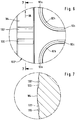
- the support rings 100 ′ can be designed with an essentially ideal cylindrical shape 132 with a radial extension R 1 to the axis of rotation 84, and instead of the recess 130, 130 ′ there is a corresponding “increase” ⁇ in the radial extension R 2 of the cross-cuts 92c to the axis of rotation 84 relative to the radial extension R 3 of the cutting legs 92a, so that the greater radial extension of the support rings 100 'is accepted with minimal contact force, but this does not deteriorate the cutting action of the transverse cutting edges 92c, since this corresponds to the amount ⁇ by a corresponding amount have greater radial extension with respect to the axis of rotation 84 than the cutting limbs 92a, since in their area the support rings 100 'have greater deformation in the radial direction due to the maximum contact force A and the minimum cutting force Smin.
Landscapes
- Life Sciences & Earth Sciences (AREA)
- Forests & Forestry (AREA)
- Engineering & Computer Science (AREA)
- Mechanical Engineering (AREA)
- Perforating, Stamping-Out Or Severing By Means Other Than Cutting (AREA)
- Crushing And Pulverization Processes (AREA)
- Details Of Cutting Devices (AREA)
- Absorbent Articles And Supports Therefor (AREA)
- Harvester Elements (AREA)
- Nonmetal Cutting Devices (AREA)
Priority Applications (2)
| Application Number | Priority Date | Filing Date | Title |
|---|---|---|---|
| ES05000091T ES2305911T3 (es) | 1998-07-29 | 1999-07-23 | Dispositivo de corte con anillo de apoyo deformable elasticamente. |
| EP05000091A EP1520668B1 (fr) | 1998-07-29 | 1999-07-23 | Dispositif de coupe ayant une bague de support déformable élastiquement |
Applications Claiming Priority (2)
| Application Number | Priority Date | Filing Date | Title |
|---|---|---|---|
| DE19834104A DE19834104A1 (de) | 1998-07-29 | 1998-07-29 | Schneidvorrichtung |
| DE19834104 | 1998-07-29 |
Related Child Applications (2)
| Application Number | Title | Priority Date | Filing Date |
|---|---|---|---|
| EP05000091A Division EP1520668B1 (fr) | 1998-07-29 | 1999-07-23 | Dispositif de coupe ayant une bague de support déformable élastiquement |
| EP05000091.8 Division-Into | 2005-01-05 |
Publications (3)
| Publication Number | Publication Date |
|---|---|
| EP0976510A2 true EP0976510A2 (fr) | 2000-02-02 |
| EP0976510A3 EP0976510A3 (fr) | 2001-08-29 |
| EP0976510B1 EP0976510B1 (fr) | 2005-03-30 |
Family
ID=7875682
Family Applications (2)
| Application Number | Title | Priority Date | Filing Date |
|---|---|---|---|
| EP99114200A Expired - Lifetime EP0976510B1 (fr) | 1998-07-29 | 1999-07-23 | Dispositif de coupe rotative |
| EP05000091A Expired - Lifetime EP1520668B1 (fr) | 1998-07-29 | 1999-07-23 | Dispositif de coupe ayant une bague de support déformable élastiquement |
Family Applications After (1)
| Application Number | Title | Priority Date | Filing Date |
|---|---|---|---|
| EP05000091A Expired - Lifetime EP1520668B1 (fr) | 1998-07-29 | 1999-07-23 | Dispositif de coupe ayant une bague de support déformable élastiquement |
Country Status (6)
| Country | Link |
|---|---|
| US (1) | US6244148B1 (fr) |
| EP (2) | EP0976510B1 (fr) |
| AT (2) | ATE291995T1 (fr) |
| DE (3) | DE19834104A1 (fr) |
| DK (2) | DK1520668T3 (fr) |
| ES (2) | ES2238793T3 (fr) |
Cited By (6)
| Publication number | Priority date | Publication date | Assignee | Title |
|---|---|---|---|---|
| EP1348525A3 (fr) * | 2002-03-28 | 2004-12-29 | McNEIL-PPC, INC. | Dispositif rotatif ayant des moyens de réglage de la pression ainsi que procédé correspondant |
| EP1721712A1 (fr) | 2005-05-11 | 2006-11-15 | Aichele Werkzeuge GmbH | Dispositif de coupe rotative, procédé de mise hors service d'un dispositif de coupe rotative et procédé de mise en oeuvre d'un dispositif de coupe rotative |
| EP1974878A1 (fr) | 2007-03-30 | 2008-10-01 | Wilhelm Aichele | Dispositif de coupe rotatif |
| CN101712163B (zh) * | 2009-11-18 | 2012-07-18 | 佛山市南海富利包装机械有限公司 | 一种螺旋横切机刀轴结构 |
| CN104552431A (zh) * | 2015-02-09 | 2015-04-29 | 晋江特锐模具有限公司 | 旋转模切装置 |
| CN105840663A (zh) * | 2016-05-06 | 2016-08-10 | 浙江翔宇密封件有限公司 | 汽车变速箱轴承密封圈的制作方法 |
Families Citing this family (32)
| Publication number | Priority date | Publication date | Assignee | Title |
|---|---|---|---|---|
| DE10040024C1 (de) * | 2000-08-16 | 2002-07-25 | Aichele Werkzeuge Gmbh | Schneidvorrichtung |
| DE10044705C1 (de) | 2000-09-09 | 2002-02-21 | Aichele Werkzeuge Gmbh | Rotationsschneidvorrichtung |
| DE10109933C1 (de) | 2001-02-21 | 2002-08-22 | Aichele Werkzeuge Gmbh | Schneidvorrichtung und Schneidwerkzeug |
| US6763871B2 (en) * | 2001-06-08 | 2004-07-20 | Converting Biophile Laboratories, Inc. | Slip cutting system |
| US20040074352A1 (en) * | 2002-10-21 | 2004-04-22 | Kimberly-Clark Worldwide, Inc. | Adjustable anvil for a flat bearer ring die |
| ES2232258B1 (es) * | 2002-11-28 | 2006-07-16 | Cimco, S.L. | Troqueladora rotativa. |
| NL1024915C2 (nl) * | 2003-12-01 | 2005-06-06 | Jean Henry Robert Madern | Inrichting voor het aanbrengen van een snede, ril en dergelijke, omvattende een plaatvormig stelsel. |
| SE527556C2 (sv) * | 2004-07-02 | 2006-04-11 | Sandvik Intellectual Property | En stödvals för en rotationsknivenhet och en rotationsknivenhet med en dylik stödvals |
| SE527838C2 (sv) * | 2004-07-02 | 2006-06-20 | Sandvik Intellectual Property | En rotationskniv och en rotationsknivanordning försedd med en dylik rotationskniv |
| SE527886C2 (sv) * | 2004-07-02 | 2006-07-04 | Sandvik Intellectual Property | En rotationskniv, en stödvals och en rotationsknivsanordning |
| SE527845C2 (sv) | 2004-11-03 | 2006-06-20 | Sandvik Intellectual Property | En stödvals för en rotationsknivenhet och en rotationsknivenhet med en dylik stödvals |
| CN100544909C (zh) * | 2005-04-07 | 2009-09-30 | 山特维克知识产权股份有限公司 | 砧鼓和设置有这种砧鼓的砧组件 |
| SE529998C2 (sv) | 2005-04-07 | 2008-02-05 | Sandvik Intellectual Property | En stödvalstrumma och en stödvalsenhet för en roterbar skäranordning |
| US7849772B2 (en) * | 2005-04-07 | 2010-12-14 | Sandvik Intellectual Property Ab | Rotary cutting apparatus comprising a cutter drum and an anvil drum |
| US20070135787A1 (en) * | 2005-12-14 | 2007-06-14 | Maria Raidel | Extensible absorbent layer and absorbent article |
| DE102006044610B4 (de) * | 2006-09-19 | 2008-11-20 | WINKLER+DüNNEBIER AG | Vorrichtung zum Schneiden und/oder Prägen eines Zuschnittes oder einer Materialbahn |
| US20100089214A1 (en) * | 2008-10-09 | 2010-04-15 | Buss Richard S | Push/Pull Rotary Cutting Apparatus Driven By Substrate |
| IT1394271B1 (it) * | 2009-05-25 | 2012-06-06 | Ima Flavour S R L Ora Ima Ind S R L | Gruppo di compressione - incisione - taglio a rulli |
| US8272923B2 (en) | 2009-08-13 | 2012-09-25 | The Procter & Gamble Company | Methods and apparatuses for anvil reconditioning |
| CN102615943A (zh) * | 2012-03-29 | 2012-08-01 | 贵州西牛王印务有限公司 | 凹印机生产线模切机防止纸张吸附装置 |
| KR101221877B1 (ko) * | 2012-04-02 | 2013-01-16 | 신용팔 | 연속형 세라믹 그린시트 하프커팅장치 |
| US20150135925A1 (en) * | 2013-11-20 | 2015-05-21 | Micro-Surface Finishing Products, Inc. | Rotary anvil |
| CN103692491B (zh) * | 2013-12-25 | 2016-01-06 | 中船重工鹏力(南京)塑造科技有限公司 | 一种刀模 |
| CN104097226A (zh) * | 2014-07-07 | 2014-10-15 | 广西梧州港德硬质合金制造有限公司 | 纸尿裤棉芯滚切装置 |
| CN105972215B (zh) * | 2016-05-06 | 2017-12-22 | 浙江翔宇密封件有限公司 | 高铁轮毂轴承密封圈的制作方法 |
| US20170341256A1 (en) | 2016-05-24 | 2017-11-30 | The Procter & Gamble Company | Rotary Anvil |
| CN106078879A (zh) * | 2016-07-05 | 2016-11-09 | 太仓路华机械制造有限公司 | 一种高精度长寿命分切机构 |
| US10478347B2 (en) | 2017-06-21 | 2019-11-19 | The Procter & Gamble Company | Nozzle assembly used to manufacture absorbent articles |
| US11292016B2 (en) | 2018-03-16 | 2022-04-05 | The Procter & Gamble Company | Nozzle assembly used to manufacture absorbent articles |
| US10857690B2 (en) * | 2018-09-11 | 2020-12-08 | The Procter & Gamble Company | Method and apparatus for adjusting and maintaining a position of a cutting surface of a perforating apparatus |
| EP3666446A1 (fr) | 2018-12-10 | 2020-06-17 | The Procter & Gamble Company | Procédé de fabrication d'un outil industriel, tel qu'un rouleau d'enclume |
| BR112023017932A2 (pt) | 2021-03-08 | 2023-12-12 | Hyperion Materials & Tech Inc | Unidade de corte rotativo |
Family Cites Families (23)
| Publication number | Priority date | Publication date | Assignee | Title |
|---|---|---|---|---|
| US3106121A (en) * | 1959-05-19 | 1963-10-08 | Smithe Machine Co Inc F L | Rotary panel cutter |
| FR1262999A (fr) * | 1960-07-21 | 1961-06-05 | Bande à dresser à poser derrière le couteau des outils à estamper | |
| DE1436912C3 (de) | 1963-03-21 | 1975-07-17 | F.L.Smithe Machine Co. Inc., New York, N.Y. (V.St.A.) | Rotationsstanze für Papier |
| US3257885A (en) * | 1964-06-19 | 1966-06-28 | Smithe Machine Co Inc F L | Rotary panel cutter |
| GB1050754A (fr) * | 1964-09-01 | 1900-01-01 | ||
| US3274874A (en) * | 1964-09-10 | 1966-09-27 | Ibm | Web perforating mechanism with resilient sleeve supported back-up roll |
| FR1575848A (fr) * | 1968-05-31 | 1969-07-25 | ||
| FR2171619A5 (fr) * | 1972-02-09 | 1973-09-21 | Michel Marcel | |
| DE2912458A1 (de) * | 1979-03-29 | 1980-10-09 | Winkler Duennebier Kg Masch | Rotationsstanze mit gegen die messerwalze abgestuetzter gegenwalze |
| DE2931109A1 (de) * | 1979-07-31 | 1981-02-19 | Agfa Gevaert Ag | Druckeinrichtung in einem mikrofilm-durchlaufaufnahmegeraet |
| US4413541A (en) * | 1980-03-10 | 1983-11-08 | Elizabeth Short Biggar | Rapid changeover printer |
| US4341525A (en) * | 1980-09-29 | 1982-07-27 | Magna-Graphics Corporation | Adjustable mounting for cooperating die cylinders |
| US4455903A (en) * | 1982-11-15 | 1984-06-26 | Preston Engravers, Inc. | Adjustable anvil roll |
| US4641558A (en) * | 1985-08-16 | 1987-02-10 | B & H Manufacturing Company | Rotatable shaft assembly |
| FR2595610A1 (fr) * | 1986-03-13 | 1987-09-18 | Gautier Jean | Dispositif de decoupe rotative ou de refoulage pour produits plats |
| US4759247A (en) * | 1987-10-22 | 1988-07-26 | Bernal Rotary Systems, Inc. | Rotary dies with adjustable cutter force |
| DE3924053A1 (de) * | 1989-07-21 | 1991-01-24 | Wilhelm Aichele | Vorrichtung zum rotationsschneiden von werkstoffbahnen |
| CH680842A5 (fr) * | 1989-09-22 | 1992-11-30 | Electro Optic Ag | |
| AU7859491A (en) * | 1990-05-10 | 1991-11-27 | Byron L. Buck | Rotary die cutting system for sheet material |
| AU2004092A (en) * | 1991-04-25 | 1992-12-21 | Noven Pharmaceuticals, Inc. | Method and apparatus for forming a transdermal drug device |
| IT1255032B (it) * | 1991-05-17 | 1995-10-13 | Focke & Co | Dispositivo per staccare ritagli (a collare) da un nastro di materiale |
| DE9202391U1 (de) * | 1992-02-25 | 1992-06-11 | Kocher + Beck Gmbh + Co. Rotationsstanztechnik Kg, 72124 Pliezhausen | Stanzwerkzeug |
| US5467678A (en) * | 1993-08-25 | 1995-11-21 | Stollenwerk; Josef A. | Apparatus for automatically applying equalized pressure to a rotary cutting die |
-
1998
- 1998-07-29 DE DE19834104A patent/DE19834104A1/de not_active Ceased
-
1999
- 1999-07-23 DK DK05000091T patent/DK1520668T3/da active
- 1999-07-23 DK DK99114200T patent/DK0976510T3/da active
- 1999-07-23 AT AT99114200T patent/ATE291995T1/de active
- 1999-07-23 ES ES99114200T patent/ES2238793T3/es not_active Expired - Lifetime
- 1999-07-23 DE DE59914778T patent/DE59914778D1/de not_active Expired - Lifetime
- 1999-07-23 EP EP99114200A patent/EP0976510B1/fr not_active Expired - Lifetime
- 1999-07-23 AT AT05000091T patent/ATE396846T1/de active
- 1999-07-23 DE DE59911825T patent/DE59911825D1/de not_active Expired - Lifetime
- 1999-07-23 ES ES05000091T patent/ES2305911T3/es not_active Expired - Lifetime
- 1999-07-23 EP EP05000091A patent/EP1520668B1/fr not_active Expired - Lifetime
- 1999-07-28 US US09/362,824 patent/US6244148B1/en not_active Expired - Lifetime
Cited By (10)
| Publication number | Priority date | Publication date | Assignee | Title |
|---|---|---|---|---|
| EP1348525A3 (fr) * | 2002-03-28 | 2004-12-29 | McNEIL-PPC, INC. | Dispositif rotatif ayant des moyens de réglage de la pression ainsi que procédé correspondant |
| EP1721712A1 (fr) | 2005-05-11 | 2006-11-15 | Aichele Werkzeuge GmbH | Dispositif de coupe rotative, procédé de mise hors service d'un dispositif de coupe rotative et procédé de mise en oeuvre d'un dispositif de coupe rotative |
| US7594461B2 (en) | 2005-05-11 | 2009-09-29 | Aichele Werkzeuge Gmbh | Rotary cutting device, a method for disengaging a rotary cutting device and a method of operating a rotary cutting device |
| EP1974878A1 (fr) | 2007-03-30 | 2008-10-01 | Wilhelm Aichele | Dispositif de coupe rotatif |
| DE102007016451A1 (de) | 2007-03-30 | 2008-10-02 | Wilhelm Aichele | Rotationsschneidevorrichtung |
| CN101712163B (zh) * | 2009-11-18 | 2012-07-18 | 佛山市南海富利包装机械有限公司 | 一种螺旋横切机刀轴结构 |
| CN104552431A (zh) * | 2015-02-09 | 2015-04-29 | 晋江特锐模具有限公司 | 旋转模切装置 |
| CN104552431B (zh) * | 2015-02-09 | 2016-05-25 | 晋江特锐模具有限公司 | 旋转模切装置 |
| CN105840663A (zh) * | 2016-05-06 | 2016-08-10 | 浙江翔宇密封件有限公司 | 汽车变速箱轴承密封圈的制作方法 |
| CN105840663B (zh) * | 2016-05-06 | 2017-12-22 | 浙江翔宇密封件有限公司 | 汽车变速箱轴承密封圈的制作方法 |
Also Published As
| Publication number | Publication date |
|---|---|
| ES2305911T3 (es) | 2008-11-01 |
| US6244148B1 (en) | 2001-06-12 |
| EP1520668B1 (fr) | 2008-05-28 |
| EP0976510A3 (fr) | 2001-08-29 |
| DE59911825D1 (de) | 2005-05-04 |
| DE59914778D1 (de) | 2008-07-10 |
| ATE291995T1 (de) | 2005-04-15 |
| ATE396846T1 (de) | 2008-06-15 |
| EP0976510B1 (fr) | 2005-03-30 |
| EP1520668A3 (fr) | 2005-08-03 |
| DE19834104A1 (de) | 2000-02-03 |
| DK1520668T3 (da) | 2008-09-29 |
| ES2238793T3 (es) | 2005-09-01 |
| DK0976510T3 (da) | 2005-07-11 |
| EP1520668A2 (fr) | 2005-04-06 |
Similar Documents
| Publication | Publication Date | Title |
|---|---|---|
| EP1520668B1 (fr) | Dispositif de coupe ayant une bague de support déformable élastiquement | |
| DE102006044610B4 (de) | Vorrichtung zum Schneiden und/oder Prägen eines Zuschnittes oder einer Materialbahn | |
| EP1551214A1 (fr) | Barre de coupe | |
| EP3409531B1 (fr) | Guidage à rouleaux | |
| EP1180419B1 (fr) | Appareil de coupe | |
| DE2611820A1 (de) | Insbesondere in verbindung mit rotations-schnelldruck-pressen verwendbare faltvorrichtung | |
| DE3605517A1 (de) | Kreissaegeanordnung | |
| EP1811194A1 (fr) | Frein à disque | |
| EP2563518B1 (fr) | Support de denture en chevron | |
| EP0523435A1 (fr) | Coupeuse transversale d'une plieuse pour des rotatives à bobines | |
| EP1974878B1 (fr) | Dispositif de coupe rotatif | |
| WO2004040154A1 (fr) | Palier d'un raccordement telescopique | |
| EP4086477A1 (fr) | Boéte de vitesses | |
| DE10305032B3 (de) | Stanzvorrichtung | |
| DE3002383B2 (de) | Reibrollgetriebe zum Umwandeln einer Drehbewegung in eine Längsbewegung und umgekehrt | |
| WO2013159947A2 (fr) | Concasseur à cylindres | |
| DE9315132U1 (de) | Drehgelenk | |
| WO2006021273A1 (fr) | Ensemble palier radial et palier radial, notamment pour un logement de broche | |
| CH638720A5 (de) | Presse. | |
| EP0363864B1 (fr) | Grignoteuse guidée par la main | |
| DE69531073T2 (de) | Verriegelungsmutter | |
| DE102013103699B4 (de) | Zahnstangenlenkung, insbesondere für Kraftfahrzeuge | |
| DE102023125879B3 (de) | Klinge für ein Mähwerk, für einen Rasenmäher und/oder für eine Motorsense | |
| EP4442111A1 (fr) | Tambour hacheur pour une récolteuse-hacheuse | |
| DE102015114475B4 (de) | Spindel mit einem auslenkbaren Werkzeugkopf |
Legal Events
| Date | Code | Title | Description |
|---|---|---|---|
| PUAI | Public reference made under article 153(3) epc to a published international application that has entered the european phase |
Free format text: ORIGINAL CODE: 0009012 |
|
| AK | Designated contracting states |
Kind code of ref document: A2 Designated state(s): AT BE CH CY DE DK ES FI FR GB GR IE IT LI LU MC NL PT SE |
|
| AX | Request for extension of the european patent |
Free format text: AL;LT;LV;MK;RO;SI |
|
| PUAL | Search report despatched |
Free format text: ORIGINAL CODE: 0009013 |
|
| AK | Designated contracting states |
Kind code of ref document: A3 Designated state(s): AT BE CH CY DE DK ES FI FR GB GR IE IT LI LU MC NL PT SE |
|
| AX | Request for extension of the european patent |
Free format text: AL;LT;LV;MK;RO;SI |
|
| RIC1 | Information provided on ipc code assigned before grant |
Free format text: 7B 26D 7/26 A, 7B 26F 1/38 B, 7B 26F 1/44 B |
|
| RAP1 | Party data changed (applicant data changed or rights of an application transferred) |
Owner name: AICHELE WERKZEUGE GMBH |
|
| 17P | Request for examination filed |
Effective date: 20020124 |
|
| AKX | Designation fees paid |
Free format text: AT BE CH CY DE DK ES FI FR GB GR IE IT LI LU MC NL PT SE |
|
| AXX | Extension fees paid |
Free format text: RO PAYMENT 20020124 |
|
| 17Q | First examination report despatched |
Effective date: 20020930 |
|
| GRAP | Despatch of communication of intention to grant a patent |
Free format text: ORIGINAL CODE: EPIDOSNIGR1 |
|
| GRAS | Grant fee paid |
Free format text: ORIGINAL CODE: EPIDOSNIGR3 |
|
| GRAA | (expected) grant |
Free format text: ORIGINAL CODE: 0009210 |
|
| AK | Designated contracting states |
Kind code of ref document: B1 Designated state(s): AT BE CH CY DE DK ES FI FR GB GR IE IT LI LU MC NL PT SE |
|
| AX | Request for extension of the european patent |
Extension state: RO |
|
| PG25 | Lapsed in a contracting state [announced via postgrant information from national office to epo] |
Ref country code: IE Free format text: LAPSE BECAUSE OF FAILURE TO SUBMIT A TRANSLATION OF THE DESCRIPTION OR TO PAY THE FEE WITHIN THE PRESCRIBED TIME-LIMIT Effective date: 20050330 Ref country code: FI Free format text: LAPSE BECAUSE OF FAILURE TO SUBMIT A TRANSLATION OF THE DESCRIPTION OR TO PAY THE FEE WITHIN THE PRESCRIBED TIME-LIMIT Effective date: 20050330 |
|
| REG | Reference to a national code |
Ref country code: GB Ref legal event code: FG4D Free format text: NOT ENGLISH |
|
| REG | Reference to a national code |
Ref country code: CH Ref legal event code: EP |
|
| REF | Corresponds to: |
Ref document number: 59911825 Country of ref document: DE Date of ref document: 20050504 Kind code of ref document: P |
|
| REG | Reference to a national code |
Ref country code: IE Ref legal event code: FG4D Free format text: LANGUAGE OF EP DOCUMENT: GERMAN |
|
| PG25 | Lapsed in a contracting state [announced via postgrant information from national office to epo] |
Ref country code: GR Free format text: LAPSE BECAUSE OF FAILURE TO SUBMIT A TRANSLATION OF THE DESCRIPTION OR TO PAY THE FEE WITHIN THE PRESCRIBED TIME-LIMIT Effective date: 20050630 |
|
| REG | Reference to a national code |
Ref country code: DK Ref legal event code: T3 |
|
| PGFP | Annual fee paid to national office [announced via postgrant information from national office to epo] |
Ref country code: LU Payment date: 20050718 Year of fee payment: 7 |
|
| REG | Reference to a national code |
Ref country code: SE Ref legal event code: TRGR |
|
| PG25 | Lapsed in a contracting state [announced via postgrant information from national office to epo] |
Ref country code: CY Free format text: LAPSE BECAUSE OF FAILURE TO SUBMIT A TRANSLATION OF THE DESCRIPTION OR TO PAY THE FEE WITHIN THE PRESCRIBED TIME-LIMIT Effective date: 20050723 |
|
| PG25 | Lapsed in a contracting state [announced via postgrant information from national office to epo] |
Ref country code: MC Free format text: LAPSE BECAUSE OF NON-PAYMENT OF DUE FEES Effective date: 20050731 Ref country code: LI Free format text: LAPSE BECAUSE OF NON-PAYMENT OF DUE FEES Effective date: 20050731 Ref country code: CH Free format text: LAPSE BECAUSE OF NON-PAYMENT OF DUE FEES Effective date: 20050731 Ref country code: BE Free format text: LAPSE BECAUSE OF NON-PAYMENT OF DUE FEES Effective date: 20050731 |
|
| GBT | Gb: translation of ep patent filed (gb section 77(6)(a)/1977) |
Effective date: 20050725 |
|
| REG | Reference to a national code |
Ref country code: ES Ref legal event code: FG2A Ref document number: 2238793 Country of ref document: ES Kind code of ref document: T3 |
|
| PG25 | Lapsed in a contracting state [announced via postgrant information from national office to epo] |
Ref country code: PT Free format text: LAPSE BECAUSE OF FAILURE TO SUBMIT A TRANSLATION OF THE DESCRIPTION OR TO PAY THE FEE WITHIN THE PRESCRIBED TIME-LIMIT Effective date: 20050907 |
|
| REG | Reference to a national code |
Ref country code: IE Ref legal event code: FD4D |
|
| PLBE | No opposition filed within time limit |
Free format text: ORIGINAL CODE: 0009261 |
|
| STAA | Information on the status of an ep patent application or granted ep patent |
Free format text: STATUS: NO OPPOSITION FILED WITHIN TIME LIMIT |
|
| ET | Fr: translation filed | ||
| REG | Reference to a national code |
Ref country code: CH Ref legal event code: PL |
|
| 26N | No opposition filed |
Effective date: 20060102 |
|
| BERE | Be: lapsed |
Owner name: AICHELE WERKZEUGE G.M.B.H. Effective date: 20050731 |
|
| PG25 | Lapsed in a contracting state [announced via postgrant information from national office to epo] |
Ref country code: LU Free format text: LAPSE BECAUSE OF NON-PAYMENT OF DUE FEES Effective date: 20060723 |
|
| REG | Reference to a national code |
Ref country code: DE Ref legal event code: R081 Ref document number: 59911825 Country of ref document: DE Owner name: AICHELE, MATTHIAS, DE Free format text: FORMER OWNER: AICHELE WERKZEUGE GMBH, 74564 CRAILSHEIM, DE Effective date: 20130627 |
|
| PGFP | Annual fee paid to national office [announced via postgrant information from national office to epo] |
Ref country code: DK Payment date: 20140710 Year of fee payment: 16 Ref country code: NL Payment date: 20140710 Year of fee payment: 16 |
|
| PGFP | Annual fee paid to national office [announced via postgrant information from national office to epo] |
Ref country code: GB Payment date: 20140723 Year of fee payment: 16 Ref country code: SE Payment date: 20140711 Year of fee payment: 16 Ref country code: AT Payment date: 20140626 Year of fee payment: 16 |
|
| REG | Reference to a national code |
Ref country code: DE Ref legal event code: R082 Ref document number: 59911825 Country of ref document: DE Representative=s name: HOEGER, STELLRECHT & PARTNER PATENTANWAELTE MB, DE |
|
| REG | Reference to a national code |
Ref country code: DK Ref legal event code: EBP Effective date: 20150731 |
|
| REG | Reference to a national code |
Ref country code: SE Ref legal event code: EUG |
|
| REG | Reference to a national code |
Ref country code: AT Ref legal event code: MM01 Ref document number: 291995 Country of ref document: AT Kind code of ref document: T Effective date: 20150723 |
|
| GBPC | Gb: european patent ceased through non-payment of renewal fee |
Effective date: 20150723 |
|
| REG | Reference to a national code |
Ref country code: NL Ref legal event code: MM Effective date: 20150801 |
|
| PG25 | Lapsed in a contracting state [announced via postgrant information from national office to epo] |
Ref country code: GB Free format text: LAPSE BECAUSE OF NON-PAYMENT OF DUE FEES Effective date: 20150723 |
|
| PG25 | Lapsed in a contracting state [announced via postgrant information from national office to epo] |
Ref country code: SE Free format text: LAPSE BECAUSE OF NON-PAYMENT OF DUE FEES Effective date: 20150724 Ref country code: AT Free format text: LAPSE BECAUSE OF NON-PAYMENT OF DUE FEES Effective date: 20150723 Ref country code: NL Free format text: LAPSE BECAUSE OF NON-PAYMENT OF DUE FEES Effective date: 20150801 |
|
| REG | Reference to a national code |
Ref country code: FR Ref legal event code: PLFP Year of fee payment: 18 |
|
| PG25 | Lapsed in a contracting state [announced via postgrant information from national office to epo] |
Ref country code: DK Free format text: LAPSE BECAUSE OF NON-PAYMENT OF DUE FEES Effective date: 20150731 |
|
| REG | Reference to a national code |
Ref country code: FR Ref legal event code: PLFP Year of fee payment: 19 |
|
| PGFP | Annual fee paid to national office [announced via postgrant information from national office to epo] |
Ref country code: FR Payment date: 20170613 Year of fee payment: 19 |
|
| PGFP | Annual fee paid to national office [announced via postgrant information from national office to epo] |
Ref country code: ES Payment date: 20170801 Year of fee payment: 19 Ref country code: DE Payment date: 20170824 Year of fee payment: 19 Ref country code: IT Payment date: 20170720 Year of fee payment: 19 |
|
| REG | Reference to a national code |
Ref country code: DE Ref legal event code: R119 Ref document number: 59911825 Country of ref document: DE |
|
| PG25 | Lapsed in a contracting state [announced via postgrant information from national office to epo] |
Ref country code: DE Free format text: LAPSE BECAUSE OF NON-PAYMENT OF DUE FEES Effective date: 20190201 Ref country code: FR Free format text: LAPSE BECAUSE OF NON-PAYMENT OF DUE FEES Effective date: 20180731 |
|
| PG25 | Lapsed in a contracting state [announced via postgrant information from national office to epo] |
Ref country code: IT Free format text: LAPSE BECAUSE OF NON-PAYMENT OF DUE FEES Effective date: 20180723 |
|
| REG | Reference to a national code |
Ref country code: ES Ref legal event code: FD2A Effective date: 20190917 |
|
| PG25 | Lapsed in a contracting state [announced via postgrant information from national office to epo] |
Ref country code: ES Free format text: LAPSE BECAUSE OF NON-PAYMENT OF DUE FEES Effective date: 20180724 |