EP0977016B1 - Magnetische kodiereinrichtung - Google Patents
Magnetische kodiereinrichtung Download PDFInfo
- Publication number
- EP0977016B1 EP0977016B1 EP98912772A EP98912772A EP0977016B1 EP 0977016 B1 EP0977016 B1 EP 0977016B1 EP 98912772 A EP98912772 A EP 98912772A EP 98912772 A EP98912772 A EP 98912772A EP 0977016 B1 EP0977016 B1 EP 0977016B1
- Authority
- EP
- European Patent Office
- Prior art keywords
- magnetic
- signal
- magnetic pole
- slit track
- phase
- Prior art date
- Legal status (The legal status is an assumption and is not a legal conclusion. Google has not performed a legal analysis and makes no representation as to the accuracy of the status listed.)
- Expired - Lifetime
Links
Images


Classifications
-
- G—PHYSICS
- G01—MEASURING; TESTING
- G01D—MEASURING NOT SPECIALLY ADAPTED FOR A SPECIFIC VARIABLE; ARRANGEMENTS FOR MEASURING TWO OR MORE VARIABLES NOT COVERED IN A SINGLE OTHER SUBCLASS; TARIFF METERING APPARATUS; MEASURING OR TESTING NOT OTHERWISE PROVIDED FOR
- G01D5/00—Mechanical means for transferring the output of a sensing member; Means for converting the output of a sensing member to another variable where the form or nature of the sensing member does not constrain the means for converting; Transducers not specially adapted for a specific variable
- G01D5/12—Mechanical means for transferring the output of a sensing member; Means for converting the output of a sensing member to another variable where the form or nature of the sensing member does not constrain the means for converting; Transducers not specially adapted for a specific variable using electric or magnetic means
- G01D5/14—Mechanical means for transferring the output of a sensing member; Means for converting the output of a sensing member to another variable where the form or nature of the sensing member does not constrain the means for converting; Transducers not specially adapted for a specific variable using electric or magnetic means influencing the magnitude of a current or voltage
- G01D5/142—Mechanical means for transferring the output of a sensing member; Means for converting the output of a sensing member to another variable where the form or nature of the sensing member does not constrain the means for converting; Transducers not specially adapted for a specific variable using electric or magnetic means influencing the magnitude of a current or voltage using Hall-effect devices
- G01D5/147—Mechanical means for transferring the output of a sensing member; Means for converting the output of a sensing member to another variable where the form or nature of the sensing member does not constrain the means for converting; Transducers not specially adapted for a specific variable using electric or magnetic means influencing the magnitude of a current or voltage using Hall-effect devices influenced by the movement of a third element, the position of Hall device and the source of magnetic field being fixed in respect to each other
-
- G—PHYSICS
- G01—MEASURING; TESTING
- G01D—MEASURING NOT SPECIALLY ADAPTED FOR A SPECIFIC VARIABLE; ARRANGEMENTS FOR MEASURING TWO OR MORE VARIABLES NOT COVERED IN A SINGLE OTHER SUBCLASS; TARIFF METERING APPARATUS; MEASURING OR TESTING NOT OTHERWISE PROVIDED FOR
- G01D5/00—Mechanical means for transferring the output of a sensing member; Means for converting the output of a sensing member to another variable where the form or nature of the sensing member does not constrain the means for converting; Transducers not specially adapted for a specific variable
- G01D5/12—Mechanical means for transferring the output of a sensing member; Means for converting the output of a sensing member to another variable where the form or nature of the sensing member does not constrain the means for converting; Transducers not specially adapted for a specific variable using electric or magnetic means
- G01D5/244—Mechanical means for transferring the output of a sensing member; Means for converting the output of a sensing member to another variable where the form or nature of the sensing member does not constrain the means for converting; Transducers not specially adapted for a specific variable using electric or magnetic means influencing characteristics of pulses or pulse trains; generating pulses or pulse trains
- G01D5/245—Mechanical means for transferring the output of a sensing member; Means for converting the output of a sensing member to another variable where the form or nature of the sensing member does not constrain the means for converting; Transducers not specially adapted for a specific variable using electric or magnetic means influencing characteristics of pulses or pulse trains; generating pulses or pulse trains using a variable number of pulses in a train
-
- G—PHYSICS
- G01—MEASURING; TESTING
- G01D—MEASURING NOT SPECIALLY ADAPTED FOR A SPECIFIC VARIABLE; ARRANGEMENTS FOR MEASURING TWO OR MORE VARIABLES NOT COVERED IN A SINGLE OTHER SUBCLASS; TARIFF METERING APPARATUS; MEASURING OR TESTING NOT OTHERWISE PROVIDED FOR
- G01D5/00—Mechanical means for transferring the output of a sensing member; Means for converting the output of a sensing member to another variable where the form or nature of the sensing member does not constrain the means for converting; Transducers not specially adapted for a specific variable
- G01D5/12—Mechanical means for transferring the output of a sensing member; Means for converting the output of a sensing member to another variable where the form or nature of the sensing member does not constrain the means for converting; Transducers not specially adapted for a specific variable using electric or magnetic means
- G01D5/244—Mechanical means for transferring the output of a sensing member; Means for converting the output of a sensing member to another variable where the form or nature of the sensing member does not constrain the means for converting; Transducers not specially adapted for a specific variable using electric or magnetic means influencing characteristics of pulses or pulse trains; generating pulses or pulse trains
- G01D5/245—Mechanical means for transferring the output of a sensing member; Means for converting the output of a sensing member to another variable where the form or nature of the sensing member does not constrain the means for converting; Transducers not specially adapted for a specific variable using electric or magnetic means influencing characteristics of pulses or pulse trains; generating pulses or pulse trains using a variable number of pulses in a train
- G01D5/2454—Encoders incorporating incremental and absolute signals
- G01D5/2455—Encoders incorporating incremental and absolute signals with incremental and absolute tracks on the same encoder
- G01D5/2457—Incremental encoders having reference marks
Definitions
- the present invention relates to a magnetic encoder apparatus.
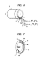
- a gear type magnetic encoder an encoder shown in Fig. 6 is used as a gear type magnetic encoder.
- a magnetic sensor 1 attached with a bias magnet 2 is oppositely arranged to a magnetic substance gear 81. Operations thereof will be described below.
- magnetic substance gear 81 is rotated and each cog approaches the magnetic sensor 1
- magnetic flux from the bias magnet 2 easily pass through the gear, and the magnetic flux applied to the magnetic sensor 1 is increased.
- the gear is further rotated and the cog goes away from the magnetic sensor 1
- magnetic resistance is increased, and the magnetic flux applied to the magnetic sensor 1 is decreased.
- a change of magnetic flux due to a change of magnetic resistance is detected by the magnetic sensor 1 composed of magnetoresistive elements, and is converted into an electric signal.
- the change of the electric signal is wave-shaped by a comparator 73 and a square wave is obtained.
- a gear is used and a change of reluctance of the magnetic circuit is utilized, and therefore this system is called a reluctance type.
- a rotation disk 10 which is a moving body, is integrally composed of a disk-like mask member 10d and a disk-like permanent magnet 9.
- the permanent magnet 9 is magnetized as a single pole in its axis direction, and structured to have a pair of magnetic poles on each side.
- the mask member 10d is made of soft magnetic substance, and on its peripheral portion, a plurality of slits are formed into ring-like arrangement with a predetermined pitch.
- a slit portion 10c having high magnetic resistance, and a strip portion 10b having low magnetic resistance are alternately formed along the rotational direction of the rotation disk 10.
- a magnetic pole 10a in which magnetic flux from the permanent magnet 9 is alternately changed along the outer peripheral portion of the rotation disk 10, is formed.
- DE 19513692 describes a rotational angular measurement system for the determination of an absolute angular position of an axis of an electric motor.
- the absolute angular position during starting of the motor is determined by a pair of sinus-cosinus signals with one period per revolution.
- the angular position is determined by incremental counting the rotational angle via a pair of sine-cosine signals with a large amount of periods per revolution.
- DE 4408623 discloses a magnetic position sensor wherein two marker tracks are arranged in parallel comprising magnetic and non-magnetic segments on a marker carrier such that a magnetic segment on one track opposes a non-magnetic segment on the other track and vice versa.
- EP 0630097 describes an electric machine rotor position encoder for an electric motor comprising a disk member mounted to rotate with the rotor shaft.
- the encoder has a set of radially extending features formed with angularly evenly spaced leading edges and unevenly spaced trailing edges. The leading edges induce a signal in a sensor that corresponds to the relative timing of power switches for each motor phase.
- the object of the present invention is to provide a thin type high performance encorder apparatus by which the production cost is lowered and plural kinds of signals can be detected, wherein the moving disk is formed into a magnetic thin plate using no permanent magnet, and a plurality of slit tracks are formed thereon, and a magnetic sensor is arranged corresponding to each slit track.
- the magnetic encoder apparatus comprises: a moving disk made of a magnetic substance including: a position detection slit track provided with a slit for detecting the position thereof; a magnetic pole detection slit track provided with a slit for detecting the magnetic pole of a motor; and a reference detection slit track provided with a slit for detecting the reference position thereof; magnetic sensors being spaced out the moving disk; bias magnets each provided on the back face of the respective, magnetic sensors and situated at where corresponds to the respective slit tracks; and a signal processing circuit for processing a signal from the magnetic sensors.
- the apparatus may be configured that: the magnetic pole detection slit track is situated outer than the position detection slit track and includes a protruded portion protruding to outer diameter of the moving disk and a notched portion; and the reference detection slit track is situated inner than the position detection slit track
- the apparatus may be configured that a non-magnetic substance is provided between each of the magnetic sensor and the bias magnet provided for the magnetic pole detection slit track
- the apparatus may be configured that: the magnetic sensor provided for the magnetic pole detection slit track includes three pairs of six magnetic sensors for a phase signal and a reversal signal thereof to detect the magnetic pole of 3-phase motor; and the signal processing circuit includes a magnetic pole detection signal processing circuit having a differential amplifier circuit to differentially amplify the three pairs of signals.
- Fig. 1 is a perspective view showing an outlook of a magnetic encoder apparatus of the present invention.
- Fig. 2 is a view showing a magnetic pole detection section of the magnetic encoder apparatus of the present invention.
- Fig. 2(a) is a side sectional view showing a magnetic sensor
- Fig. 2(b) is a partial plan view showing a slit track for the magnetic pole detection.
- Fig. 3 is a view showing waveform of a pole detection signal of the present invention.
- Fig. 4 is a perspective view showing another embodiment of the magnetic encoder apparatus of the present invention.
- Fig. 5 is a circuit diagram showing a signal processing circuit for the magnetic pole detection of the present invention.
- Fig. 6 is a perspective view showing a structure of the conventional example.
- Fig. 7 is a perspective view showing a structure of a main portion of anther conventional example.
- Fig. 1 is a perspective view showing an outlook of a reluctance type magnetic rotary encoder of the present invention.
- numeral 11 denotes magnetic sensor 11 for position detection.
- Numerals 13a-13c are magnetic sensors for detecting magnetic pole positions of a motor.
- Numeral 12 denotes a magnetic sensor for detecting the reference.
- Numeral 21 denotes a bias magnet to apply the magnetic flux onto the magnetic sensor for reference detection 12.
- Numerals 23a-23c are bias magnets to apply the magnetic flux onto the magnetic sensors 13a-13c.
- Numeral 5 denotes a moving disk made of a magnetic substance attached to the moving body.
- Numeral 6 denotes a signal processing circuit into which a magnetic sensor signal is inputted and from which a square wave is outputted.
- a slit track 31 for the position detection, a slit track 32 for the reference detection, and a slit track 33 for the magnetic pole detection are formed by a method of etching, or the like.
- the resistance value of the magnetic sensor is changed due to a change of the magnetic flux depending on existence or not of the slit, and this change is converted into an electric signal. Further, this electric signal is wave-shaped in a signal processing circuit 8 and the square wave is obtained.
- the arrangement of each slit track may not be the arrangement in Fig. 1, but may be arbitrarily selected.
- Fig. 2 is a view showing a magnetic pole detection section of the magnetic encoder apparatus of the present invention.
- Fig. 2(a) is a side sectional view showing a magnetic sensor 13
- Fig. 2(b) is a partial plan view of the slit track 33 for the magnetic pole detection.
- numeral 23a is a bias magnet
- numeral 4 is a non-magnetic substance.
- the slit track 33 is composed of a protruded portion 331 protruding in the outer diameter direction and a notched portion 332. From the magnetic sensor 13a for the magnetic pole detection, DC bias voltage as shown by an example of a signal output shown in Fig.
- the non-magnetic substance 4 is set and arranged.
- the non-magnetic substance 4 may also be formed of epoxy resin which is used in circuit boards, or the like.
- Fig. 4 is a perspective view showing the structure of the magnetic sensor 13 for the magnetic pole detection of the present invention.
- the slits arranged in the circumferencial direction of the moving disk are divided into 6 units, that is, for each 60°, for a 3 phase 6 pole motor.
- b1-b6 are bias magnets
- s1-s6 are magnetic sensors, and respectively for U phase, U* phase, V phase, V* phase, W phase, and W* phase.
- a U* phase signal is a reversal signal of the U phase signal
- a V* phase signal is a reversal signal of the V phase signal
- a W* phase signal is a reversal signal of the W phase signal
- the U phase magnetic sensor is set as the reference, the U* phase magnetic sensor is arranged at a position of -60°, the V phase magnetic sensor is at a position of +60°, the V* phase magnetic sensor is at a position of -20°, the W phase magnetic sensor is at a position of -40°, and the W* phase magnetic sensor is arranged at a position of +20°, so that the phase difference among the U phase signal, V phase signal, and W phase signal is respectively electrically 120°, and thus shifted signal is obtained.
- the U phase-W* phase signals are differential-amplified in a signal processing circuit 7 for the magnetic pole detection and inputted into the comparator. and the square wave is outputted.
- Fig. 5 is a circuit diagram of the signal processing circuit 7 for the magnetic pole detection.
- numeral 71 is an amplifier circuit
- numeral 72 is a differential amplifier circuit
- numeral 73 is a comparator.
- the U phase -W* phase signals are amplified in the amplifiers 711-716
- the U* phase, V* phase, and W* phase signals are reversed in the differential amplifiers 721-723, and added to the U phase, V phase, and W phase signals, and their output signals are shaped into the square waves in the comparator 73, and the U phase, V phase and W phase signals are respectively outputted.
- a thin type magnetic encoder whose production cost is low, and in which a plurality of signals can be obtained by single moving disk can be realized. Further, because a magnetic sensor is arranged oppositely to the slit track in the moving slit surface, a size in the diameter direction can be reduced.
- the non-magnetic substance is provided between the magnetic sensor and the bias magnet, and because appropriate DC bias voltage can be obtained by adjusting the thickness of the non-magnetic substance, the detection signal whose signal amplitude is large to the DC bias voltage, is obtained, and further, a high performance magnetic encoder which is resistible to the temperature change, and is resistible to noise, can be obtained by the aid of the differential amplification.
- the magnetic encoder apparatus of the present invention is lower in the production cost and smaller in the size, and the detection signal having larger signal amplitude to the DC bias value can be obtained therefrom, and further, the apparatus is appropriate for a high performance encoder which is resistible to the temperature change and noise, by the aid of the differential amplification.
Landscapes
- Physics & Mathematics (AREA)
- General Physics & Mathematics (AREA)
- Transmission And Conversion Of Sensor Element Output (AREA)
Claims (4)
- Eine magnetische Codiervorrichtung umfassend:worin die bewegliche Scheibe einschließt:eine bewegliche Scheibe aus einer magnetischen Substanz und mit Schlitzen, die in einer Umfangsrichtung angeordnet sind, zum Erfassen einer Position davon;magnetische Sensoren, die gegenüber der Oberfläche der beweglichen Scheibe angeordnet sind;vormagnetisierte Magnete, die jeweils auf der Rückseite der entsprechenden magnetischen Sensoren bereitgestellt ist; undein Signalverarbeitungsschaltkreis zur Verarbeitung eines Signals von den magnetischen Sensoren;worin die vormagnetisierten Magnete entsprechend den jewiligen Schlitzspuren angeordnet sind.eine Positionserfassungsschlitzspur, die mit einer Vielzahl von Schlitzen zur Erfassung der Winkelposition der beweglichen Scheibe ausgestattet ist;eine Magnetpolerfassungsschlitzspur, die mit einem Schlitz zur Erfassung des Magnetpols eines Motors ausgestattet ist; undeine Referenzerfassungsschlitzspur, die mit einem Schlitz zur Erfassung einer Referenzposition auf der beweglichen Scheibe ausgestattet ist; und
- Die magnetische Codiervorrichtung wie in Anspruch 1 ausgeführt, worin die Magnetpolerfassungsschlitzspur radial außerhalb der Positionserfassungsschlitzspur angeordnet ist und einen vorspringenden Abschnitt einschließt, der über den äußeren Durchmesser der beweglichen Scheibe vorsteht und einen eingekerbten Abschnitt aufweist, und
worin die Referenzerfassungsschlitzspur innerhalb der Positionserfassungsschlitzspur angeordnet ist. - Die magnetische Codiervorrichtung wie in den Ansprüchen 1 oder 2 ausgeführt, worin eine nicht magnetische Substanz zwischen jedem der magnetischen Sensoren und den vormagnetisierten Magneten bereitgestellt ist, die für die magnetische Polerfassungsschlitzspur bereitgestellt sind.
- Die magnetische Codiervorrichtung wie in den Ansprüchen 1 oder 3 ausgeführt, worin der magnetische Sensor, der für die magnetische Polerfassungsschlitzspur bereitgestellt ist, drei Paare von magnetischen Sensoren für ein Phasensignal und ein Umkehrsignal davon einschließt, um die magnetischen Pole eines Dreiphasenmotors zu erfassen, und
worin der Signalverarbeitungsschaltkreis einen magnetischen Polerfassungssignalverarbeitungsschaltkreis einschließt mit einem Differenzverstärkerschaltkreis um die drei Paare von Signalen differenziell zu verstärken.
Applications Claiming Priority (3)
| Application Number | Priority Date | Filing Date | Title |
|---|---|---|---|
| JP9115214A JPH10293042A (ja) | 1997-04-16 | 1997-04-16 | 磁気式エンコーダ装置 |
| JP11521497 | 1997-04-16 | ||
| PCT/JP1998/001677 WO1998046968A1 (en) | 1997-04-16 | 1998-04-10 | Magnetic encoder |
Publications (3)
| Publication Number | Publication Date |
|---|---|
| EP0977016A1 EP0977016A1 (de) | 2000-02-02 |
| EP0977016A4 EP0977016A4 (de) | 2000-07-05 |
| EP0977016B1 true EP0977016B1 (de) | 2003-02-26 |
Family
ID=14657198
Family Applications (1)
| Application Number | Title | Priority Date | Filing Date |
|---|---|---|---|
| EP98912772A Expired - Lifetime EP0977016B1 (de) | 1997-04-16 | 1998-04-10 | Magnetische kodiereinrichtung |
Country Status (7)
| Country | Link |
|---|---|
| US (1) | US6160499A (de) |
| EP (1) | EP0977016B1 (de) |
| JP (1) | JPH10293042A (de) |
| KR (1) | KR100573461B1 (de) |
| CN (1) | CN1236285C (de) |
| DE (1) | DE69811652T2 (de) |
| WO (1) | WO1998046968A1 (de) |
Cited By (1)
| Publication number | Priority date | Publication date | Assignee | Title |
|---|---|---|---|---|
| DE102004063245B4 (de) * | 2004-07-14 | 2016-05-04 | Mitsubishi Denki K.K. | Magnetischer Detektor |
Families Citing this family (22)
| Publication number | Priority date | Publication date | Assignee | Title |
|---|---|---|---|---|
| DE69827818T2 (de) * | 1997-09-08 | 2005-04-21 | Yaskawa Denki Kitakyushu Kk | Magnetische kodiereinrichtung |
| JP4269246B2 (ja) * | 2001-05-18 | 2009-05-27 | 株式会社安川電機 | エンコーダおよびエンコーダ付モータ |
| US6963064B2 (en) * | 2002-06-14 | 2005-11-08 | Pem Management, Inc. | Multi-resolution reflective optical incremental encoder |
| JP4621987B2 (ja) * | 2003-10-24 | 2011-02-02 | 株式会社安川電機 | 磁気式エンコーダ装置およびアクチュエータ |
| CN100390505C (zh) * | 2006-01-20 | 2008-05-28 | 安徽金海迪尔信息技术有限责任公司 | 绝对式多圈磁编码器 |
| JP5273481B2 (ja) * | 2006-04-10 | 2013-08-28 | ティムケン ユーエス エルエルシー | 回動デバイス位置検知システムおよび方法 |
| JP5046850B2 (ja) * | 2007-10-22 | 2012-10-10 | 株式会社森精機製作所 | 位置検出装置、及び、バイアス磁界発生装置 |
| CN101876557B (zh) * | 2009-04-30 | 2013-03-06 | 浙江中科德润科技有限公司 | 位置检测装置及其信号处理方法 |
| CN101846531B (zh) * | 2010-05-28 | 2011-08-24 | 江苏斯沃特电气有限公司 | 多极复合式磁编码器 |
| CN102042840B (zh) * | 2010-09-07 | 2014-05-07 | 株洲威森机车配件有限公司 | 一种双路格雷码磁编码装置 |
| EP2642252A1 (de) | 2012-03-22 | 2013-09-25 | Schleifring und Apparatebau GmbH | Magnetischer Positionskodierer |
| WO2013176104A1 (ja) * | 2012-05-22 | 2013-11-28 | 三菱電機株式会社 | 磁気式回転角検出器 |
| CN102868279B (zh) * | 2012-09-12 | 2014-09-10 | 沈阳市蓝光自动化技术有限公司 | 低速电机磁旋转编码器 |
| CN103148774B (zh) * | 2013-03-11 | 2016-08-24 | 黎友盛 | 起重机大小车用座标式相对位移检测磁尺 |
| CN104333178B (zh) * | 2014-11-15 | 2017-08-22 | 欧佩德伺服电机节能系统有限公司 | 一种电机编码器转换连接结构的安装方法 |
| CN106052723B (zh) * | 2016-06-01 | 2019-12-27 | 江苏森尼克电子科技有限公司 | 一种磁编码器 |
| CN106767955A (zh) * | 2016-12-27 | 2017-05-31 | 江西省智成测控技术研究所有限责任公司 | 一种基于磁编码器的离轴式绝对角度测量的实现方法 |
| CN108768122B (zh) * | 2018-07-13 | 2025-03-28 | 深圳奥思添医疗科技有限公司 | Oct用直驱模组 |
| DE102020109534A1 (de) * | 2020-04-06 | 2021-10-07 | Hubtex Maschinenbau Gmbh & Co. Kg | Flurförderzeug mit Motor-Drehzahlerfassung und Asynchronmotor |
| DE102020117752A1 (de) * | 2020-07-06 | 2022-01-13 | Knorr-Bremse Systeme für Nutzfahrzeuge GmbH | Omnidirektionaler Drehzahl- und Richtungssensor |
| EP4468574A4 (de) * | 2022-01-17 | 2026-01-14 | Takano Co Ltd | Drehantriebsvorrichtung |
| CN116381267B (zh) * | 2023-02-27 | 2026-04-14 | 西门子(中国)有限公司 | 传感器系统和利用其测量旋转轴的旋转参数的方法 |
Family Cites Families (11)
| Publication number | Priority date | Publication date | Assignee | Title |
|---|---|---|---|---|
| JPS5940856U (ja) * | 1982-09-06 | 1984-03-15 | 富士重工業株式会社 | 回転数検出器 |
| GB8322886D0 (en) * | 1983-08-25 | 1983-09-28 | Lucas Ind Plc | Transducer means |
| JPH0552584A (ja) * | 1991-08-28 | 1993-03-02 | Toshiba Corp | 磁気式エンコーダ |
| US5444370A (en) * | 1993-03-18 | 1995-08-22 | Honeywell Inc. | Magnetic angular position sensor with two magnetically sensitive components arranged proximate two target tracks having complimentary magnetic and nonmagnetic segments |
| GB9311694D0 (en) * | 1993-06-07 | 1993-07-21 | Switched Reluctance Drives Ltd | Electric machine rotor prosition encoder |
| JPH0731116A (ja) * | 1993-07-06 | 1995-01-31 | Matsushita Electric Ind Co Ltd | ブラシレスモータ用磁気式エンコーダ |
| JPH0743375A (ja) * | 1993-07-30 | 1995-02-14 | Matsushita Electric Works Ltd | 回転検出装置 |
| DE4333800A1 (de) * | 1993-10-04 | 1995-04-06 | Deutsche Automobilgesellsch | Vorrichtung zur Drehwinkeldetektierung |
| JPH07209315A (ja) * | 1994-01-26 | 1995-08-11 | Mitsubishi Electric Corp | 電磁式回転センサ |
| DE19513692C1 (de) * | 1995-04-11 | 1996-07-18 | Stegmann Max Antriebstech | Drehwinkelmeßsystem |
| US5774074A (en) * | 1997-01-21 | 1998-06-30 | Hewlett-Packard Company | Multi-track position encoder system |
-
1997
- 1997-04-16 JP JP9115214A patent/JPH10293042A/ja active Pending
-
1998
- 1998-04-10 EP EP98912772A patent/EP0977016B1/de not_active Expired - Lifetime
- 1998-04-10 US US09/402,884 patent/US6160499A/en not_active Expired - Fee Related
- 1998-04-10 KR KR1019997009400A patent/KR100573461B1/ko not_active Expired - Fee Related
- 1998-04-10 CN CNB988061287A patent/CN1236285C/zh not_active Expired - Fee Related
- 1998-04-10 DE DE69811652T patent/DE69811652T2/de not_active Expired - Fee Related
- 1998-04-10 WO PCT/JP1998/001677 patent/WO1998046968A1/ja not_active Ceased
Cited By (1)
| Publication number | Priority date | Publication date | Assignee | Title |
|---|---|---|---|---|
| DE102004063245B4 (de) * | 2004-07-14 | 2016-05-04 | Mitsubishi Denki K.K. | Magnetischer Detektor |
Also Published As
| Publication number | Publication date |
|---|---|
| CN1260871A (zh) | 2000-07-19 |
| DE69811652D1 (de) | 2003-04-03 |
| EP0977016A4 (de) | 2000-07-05 |
| WO1998046968A1 (en) | 1998-10-22 |
| JPH10293042A (ja) | 1998-11-04 |
| CN1236285C (zh) | 2006-01-11 |
| DE69811652T2 (de) | 2003-09-18 |
| EP0977016A1 (de) | 2000-02-02 |
| KR20010006316A (ko) | 2001-01-26 |
| KR100573461B1 (ko) | 2006-04-24 |
| US6160499A (en) | 2000-12-12 |
Similar Documents
| Publication | Publication Date | Title |
|---|---|---|
| EP0977016B1 (de) | Magnetische kodiereinrichtung | |
| EP1014039B1 (de) | Magnetische kodiereinrichtung | |
| EP2693169B1 (de) | Absolutkodierungsvorrichtung und motor | |
| CN101535816B (zh) | 处理编码器信号的方法 | |
| US6400143B1 (en) | Digital sensor of relative position | |
| US4732494A (en) | Bearing or roller bearing with data sensor | |
| EP3161420B1 (de) | Drehwinkelmessvorrichtung und -messverfahren | |
| US20100301845A1 (en) | Absolute measurement steering angle sensor arrangement | |
| JP4103018B2 (ja) | サーボモータ | |
| JP4352189B2 (ja) | 磁気式エンコーダおよび磁気式エンコーダ付モータ | |
| US6515471B1 (en) | Absolute position hall string sensor | |
| US20020175673A1 (en) | Arrangement for determining the direction of movement of a motion sensor element | |
| US4701650A (en) | Brushless motor with phase cancelling leads for rotational speed detector pattern | |
| JP2000065596A5 (ja) | 磁気式エンコーダおよび磁気式エンコーダ付モータ | |
| US20020175678A1 (en) | Arrangement for determining the position of a motion sensor element | |
| US4701649A (en) | Brushless motor with symmetrical leads for preventing signal distortion | |
| JPS59147213A (ja) | 磁気回転センサ | |
| EP1016852A1 (de) | Positionssensor | |
| JPS61278713A (ja) | 磁気式ロ−タリ−エンコ−ダ− | |
| JPH0754595B2 (ja) | Vtr用ドラムモ−タにおけるスイツチングパルス発生装置 | |
| JPS6063413A (ja) | 回転検出器 | |
| JPS61189414A (ja) | 磁束密度変化検知装置 | |
| JPH0441282B2 (de) | ||
| JPWO1999013296A1 (ja) | 磁気式エンコーダ装置 | |
| JPH08233841A (ja) | 回転センサ |
Legal Events
| Date | Code | Title | Description |
|---|---|---|---|
| PUAI | Public reference made under article 153(3) epc to a published international application that has entered the european phase |
Free format text: ORIGINAL CODE: 0009012 |
|
| 17P | Request for examination filed |
Effective date: 19991015 |
|
| AK | Designated contracting states |
Kind code of ref document: A1 Designated state(s): DE GB |
|
| A4 | Supplementary search report drawn up and despatched |
Effective date: 20000519 |
|
| AK | Designated contracting states |
Kind code of ref document: A4 Designated state(s): DE GB |
|
| RIC1 | Information provided on ipc code assigned before grant |
Free format text: 7G 01D 5/245 A, 7G 01D 5/14 B, 7G 01D 5/16 B |
|
| 17Q | First examination report despatched |
Effective date: 20011030 |
|
| GRAG | Despatch of communication of intention to grant |
Free format text: ORIGINAL CODE: EPIDOS AGRA |
|
| GRAG | Despatch of communication of intention to grant |
Free format text: ORIGINAL CODE: EPIDOS AGRA |
|
| GRAH | Despatch of communication of intention to grant a patent |
Free format text: ORIGINAL CODE: EPIDOS IGRA |
|
| GRAH | Despatch of communication of intention to grant a patent |
Free format text: ORIGINAL CODE: EPIDOS IGRA |
|
| GRAA | (expected) grant |
Free format text: ORIGINAL CODE: 0009210 |
|
| AK | Designated contracting states |
Designated state(s): DE GB |
|
| REG | Reference to a national code |
Ref country code: GB Ref legal event code: FG4D |
|
| REF | Corresponds to: |
Ref document number: 69811652 Country of ref document: DE Date of ref document: 20030403 Kind code of ref document: P |
|
| PLBE | No opposition filed within time limit |
Free format text: ORIGINAL CODE: 0009261 |
|
| STAA | Information on the status of an ep patent application or granted ep patent |
Free format text: STATUS: NO OPPOSITION FILED WITHIN TIME LIMIT |
|
| 26N | No opposition filed |
Effective date: 20031127 |
|
| PGFP | Annual fee paid to national office [announced via postgrant information from national office to epo] |
Ref country code: DE Payment date: 20090402 Year of fee payment: 12 |
|
| PGFP | Annual fee paid to national office [announced via postgrant information from national office to epo] |
Ref country code: GB Payment date: 20090408 Year of fee payment: 12 |
|
| GBPC | Gb: european patent ceased through non-payment of renewal fee |
Effective date: 20100410 |
|
| PG25 | Lapsed in a contracting state [announced via postgrant information from national office to epo] |
Ref country code: DE Free format text: LAPSE BECAUSE OF NON-PAYMENT OF DUE FEES Effective date: 20101103 |
|
| PG25 | Lapsed in a contracting state [announced via postgrant information from national office to epo] |
Ref country code: GB Free format text: LAPSE BECAUSE OF NON-PAYMENT OF DUE FEES Effective date: 20100410 |