EP0977211A2 - Composant électrique avec rétrécissement dans un élément PTC en polymère - Google Patents
Composant électrique avec rétrécissement dans un élément PTC en polymère Download PDFInfo
- Publication number
- EP0977211A2 EP0977211A2 EP99810624A EP99810624A EP0977211A2 EP 0977211 A2 EP0977211 A2 EP 0977211A2 EP 99810624 A EP99810624 A EP 99810624A EP 99810624 A EP99810624 A EP 99810624A EP 0977211 A2 EP0977211 A2 EP 0977211A2
- Authority
- EP
- European Patent Office
- Prior art keywords
- electrical component
- constrictions
- constriction
- component according
- ptc polymer
- Prior art date
- Legal status (The legal status is an assumption and is not a legal conclusion. Google has not performed a legal analysis and makes no representation as to the accuracy of the status listed.)
- Withdrawn
Links
Images

Classifications
-
- H—ELECTRICITY
- H01—ELECTRIC ELEMENTS
- H01C—RESISTORS
- H01C7/00—Non-adjustable resistors formed as one or more layers or coatings; Non-adjustable resistors made from powdered conducting material or powdered semi-conducting material with or without insulating material
- H01C7/02—Non-adjustable resistors formed as one or more layers or coatings; Non-adjustable resistors made from powdered conducting material or powdered semi-conducting material with or without insulating material having positive temperature coefficient
- H01C7/028—Non-adjustable resistors formed as one or more layers or coatings; Non-adjustable resistors made from powdered conducting material or powdered semi-conducting material with or without insulating material having positive temperature coefficient consisting of organic substances
Definitions
- the present invention relates to an electrical component with a PTC polymer element.
- Such components are e.g. B. known from EP 0 655 760 A2, according to which a PTC polymer element is used for overcurrent limitation and the PTC polymer element for this purpose in series with a switch disconnector is interconnected.
- a current over one by designing the PTC polymer element certain threshold value creates a fast non-linear increase in the electrical resistance of the PTC polymer element and thereby limits the overcurrents.
- the switch disconnector can then completely interrupt the limited current.
- PTC polymer element and PTC polymer material also such elements and includes materials that contain components without PTC behavior, for example linear resistance elements or varistor elements added are.
- this invention relates to such an electrical component, in which the PTC polymer element does not have a constant current-carrying cross-sectional area has, but constricted the line cross-sectional area is.
- the main flow direction defining this cross-sectional area is in general by external contacts on the PTC polymer element or by given the geometry. However, it does not have to occur to everyone correspond to local current directions, but only to a certain extent Average.
- the current density locally increased relative to the rest of the PTC polymer element, so that predetermined is at which point the non-linear increase in resistance of the PTC effect begins when the corresponding current threshold values are reached.
- EP 0 798 750 A2 again shows a resistance system made of a PTC polymer element with varistor elements, in which such constrictions are provided are.
- U.S. Patent 3,351,882 also shows constricted PTC polymer elements, with the justification given here that by suitable Choice of constrictions overheating near the contact points of the PTC polymer element should be avoided.
- the European patent EP 0 should also be mentioned as prior art 038 715 B1, in which a specific design of a PTC polymer element with a constriction a very quick response within a few seconds or less.
- a PTC polymer element with a constriction is also shown in JP 4-130602 with patent abstract, DE 196 26 238 A1 and the US patents 4,317,027 and 4,352,083.
- the latter two publications show in particular that constrictions due to adjacent recesses can be formed in a PTC polymer material.
- the present Invention based on the technical problem of an electrical component with a Specify PTC polymer element in which the PTC polymer element particularly quick response and in the normally conductive case one good current carrying capacity as well as a reliable and permanent one Operation shows.
- the invention provides an electrical component with a PTC polymer element before that a constriction of the cross-sectional area perpendicular to a main flow direction, an opening angle of Constriction in a longitudinal section plane containing the main flow direction is at least 100 °.
- the invention thus relates to PTC polymer elements in which the State of the art constriction known per se runs particularly steeply, thus has a particularly large opening angle.
- the constriction is limited only the cross-sectional area is formed in one direction, the PTC polymer element So it has a two-dimensional basic structure, so to speak.
- the definition of the invention relates to an opening angle in a longitudinal section plane containing the main flow direction through the PTC polymer element.
- the invention relates to PTC polymer elements in which the value of 100 ° for the Opening angle reached or exceeded in at least one longitudinal section plane becomes.
- the opening angle is defined from the perspective of the point with minimal Cross-section in the constriction, i.e. in the sense of widening starting from the point of minimal cross-section.
- the right and left opening angles are combined on one side to a total opening angle of at least 100 °, however occurs in two parts at different vertices.
- the Vertices of the two parts of the opening angle due to the transverse expansion the minimum cross-sectional area in the considered longitudinal section plane separated from each other. It is not necessary that the two parts of the total opening angle are identical, but preferred.
- the (sum) opening angle must be of the minimum Cross-sectional area seen from at least one of the two sides , but preferably applies to both sides.
- Route sections angled to the main flow direction on both sides of the constriction do not necessarily have to be regularly shaped. It is sufficient, if a route section fulfilling the angular condition according to the invention can be defined as the mean. However, it is preferred that the constriction flanks essentially on both sides of the minimum cross-sectional area are straight and thus essentially the opening angle as a whole define without averaging. Then it cannot be clear local deviations from the steep formation preferred according to the invention the constriction.
- the mentioned value of 100 ° for the total opening angle (e.g. a Partial opening angle on the right of 50 ° and a partial opening angle on the left of 50 °) forms the lower bound for the invention. In fact, however, are still larger opening angles are cheaper, so opening angles are increasingly preferred from Z. B. 105 °, 110 °, 115 ° or 120 ° and above.
- Another important aspect of the invention is that with the values according to the invention for the opening angle with good current carrying capacity attractive constrictions can be produced so quickly, that with a series connection of at least two such constrictions even without parallel connection of a varistor or resistance element simultaneous response is guaranteed and therefore really a multiplication the respective dielectric strength of a constriction is possible.
- the PTC materials are apparently one certain inherent inertia regarding the heat transfer from the typically conductive particles present in these PTC materials on the polymer matrix by its response to the temperature increase show the actual PTC effect. Is the response behavior significantly faster than this inherent sluggishness, so can really simultaneous response of serially connected points of contact or constrictions be guaranteed. This is a particularly important aspect of the invention because it is a theoretically unlimited increase the dielectric strength of the entire electrical component becomes possible.
- parallel connections are also provided preferred at least two of the constrictions.
- this has the advantage of better mechanical stability, especially with larger ones Total line cross-sectional areas.
- it results from the Allocation of the necessary line cross-sectional area to two or more parallel contact points also the advantage of an improved Cooling effect, d. H. a better thermal coupling of the contact points or the places of the minimum line cross-sectional area on the remaining volume of the PTC polymer element.
- the parallel connections and series connections can also be combined, resulting in a field of constrictions. This determines the extension (s) of the field transverse to the main flow direction the line cross-sectional area and together with others Parameters the current carrying capacity, while the "depth" of the field, ie the Series connection number that determines dielectric strength.
- Another aspect of the invention in turn relates to the dielectric strength, in this case, however, already related to the individual constriction.
- the invention provides, essentially in the main flow direction a bridge in the center of the constriction, i.e. a bridge with in essentially the minimum cross-sectional area of the constriction.
- This web should be extended so far in the main flow direction that - with a length depending on the respective parameters of the used PTC polymer material - a zone of high resistance completely can build up in the area of the minimum cross-sectional area.
- a range between 0.5 and 4 mm is typically preferred between 1 and 2 mm for the extension of the web in the main flow direction to provide.
- Bridge lengths that are too long are disadvantageous because they are for the Invention can deteriorate essential cooling effect.
- the line cross-sectional area perpendicular to the main current direction is relatively strong restrict, by at least a factor of 3, preferably 4 or 5.
- it is divided into at least two connected in parallel Constrictions for reasons of stability and also because of shorter thermal diffusion paths advantageous. This is especially true for very strong reductions in cross-sectional area.
- the working examples complete this point.
- the invention relates to an electrical component with a PTC polymer element.
- the exemplary embodiments show PTC polymer elements for electrical resistors as a concrete variant of a electrical component. These electrical resistors are used as current limiting devices in automatic circuit breakers. Other electrical Components can of course be made in a similar way with PTC polymer elements be provided to the PTC effect for certain electrotechnical To use purposes. Because electrical resistors with PTC polymer elements are state of the art in the following, only the PTC polymer elements themselves shown and explained. The connection to external contacts and the use in an external circuit are the Known specialist without further explanation.
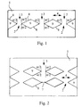
- FIG. 1 now shows a PTC polymer element 1, which is for a main flow direction 3 is designed, as indicated by the arrows, that is vertical in the figure from top to bottom (or bottom to top).
- Figure 1 shows a longitudinal sectional plane, the main flow direction 3 contains.
- this longitudinal section plane are horizontal in the sense of the figure three next to each other except for their respective position in the PTC polymer element 1 similar constrictions 2 are provided.
- These constrictions are formed by two diamond-shaped in the longitudinal section plane air-filled recesses 9 in solid material and two further recesses 9 right and left on the edge (in the sense of notches) of the solid material.
- the opening angle ⁇ which is essential according to the invention occurs, as already explained above, on both respective sides of a constriction 2 each in two parts, which are the same size in the present case.
- FIG. 2 shows a structure largely corresponding to FIG. 1, but in the case of the system shown in Figure 1 from constrictions 2 and recesses 9 provided twice and in the main flow direction 3 one behind the other is.
- the constrictions 2 and recesses 9 lie in the (vertical) Main flow direction 3 aligned one behind the other.
- the distance 10 between the locations of the smallest cross-sectional areas 7 in the main flow direction 3 the structure in FIG. 2 is approximately 8 mm apart. This distance of 8 mm is four times the minimum transverse expansion of the Constrictions 2 by 2 mm.
- FIG. 3 shows an exemplary embodiment that has been modified in three ways compared to FIG. 2.
- a series connection of two constrictions 2 a series connection of a plurality of constrictions 2 in each "pillar" of parallel connection has become, whereby only the top one four constrictions are shown.
- all largely sharp in the structures of FIG. 1 and FIG. 2 Corners somewhat rounded, what happens when machining a PTC polymer block or a mold for an injection or casting process Offers simplifications. These roundings do not change anything essential the functionality of the geometry shown.
- the locations of the minimum line cross-sectional area 7 are to be webs 5 extended, which extend over a distance 6 in the main flow direction 3. This can be seen better in the detail representation in FIG. 4.
- the length 6 of the webs 5 is 1 mm without the inclusion of the curve towards the opening angle, taking into account a part of this Curvature between 1-2 mm.
- the distance 10 is the Set minimum cross-section 7 in the main current direction 3 in this Embodiment 1 mm longer than in Figure 2, if one of each the center of the web calculated from; the web length is therefore in addition to this distance provided (add reference numeral 10).
- the remaining dimensions correspond to the values given above.
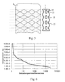
- FIG. 5 shows a top view of this figure, which corresponds identically as far as Figure 3.
- the surface is and corrugated the bottom of this PTC polymer element 1, d. H. has side Recesses or notches 11 also on the top and bottom on. Accordingly, there are also cutouts in this "third dimension" 12 in the solid material of the PTC polymer element 1.
- the wave-like recesses 11 on the top and bottom and the recesses 12 in solid material complete the cutouts already described with reference to FIGS.
- the PTC polymer element is made of ETTB from 50% ETFE and 50% TiB 2 .
- the material was milled or cut out of a block, but for large-scale production, various injection and casting processes according to the prior art are also conceivable.
- the corresponding metal contacts u. U. can be molded in one operation.
- FIGS. 3, 4 and 5 are compared to the Structures in Figures 1 and 2 by the formation of the constrictions 2 in the web shape described with regard to the dielectric strength in the response state improved.
- a typical value for a single constriction 2 is in the range of 150-300 V (rms value) depending on the material.
- a low voltage protection system in the Range of z. B. 690 V are accordingly several, a maximum of five serial interconnected constrictions 2 necessary.
- FIG. 6 shows measured values on a Experimental pattern of the structure of Figure 2, namely for the response time the ordinate versus the quotient from the actual load current and the maximum design current in the normally conductive state. It can be seen that the curve lengthened too much with small overcurrents Response times increases, so the PTC polymer element 1 in the range small multiple of the nominal current only responds slowly.
- This behavior is basically typical of PTC polymer materials; in the invention Pattern is the response behavior in the immediate vicinity, for example below 1.3 times the nominal current, but even slower than at conventional comparison pieces. This illustrates the improved cooling effect due to the geometry according to the invention, the permanent load near the rated current for a long time.
- the response behavior of the PTC polymer element according to the invention 1 above a value approximately 1.3 times to 2 times of the nominal current considerably faster, by 1-2 powers of ten faster than with conventional examples. This applies approximately until 100 times the nominal current; thereafter the pattern according to the invention is still better than the state of the art, but loses its lead.
Landscapes
- Engineering & Computer Science (AREA)
- Microelectronics & Electronic Packaging (AREA)
- Ceramic Engineering (AREA)
- Physics & Mathematics (AREA)
- Electromagnetism (AREA)
- Thermistors And Varistors (AREA)
Applications Claiming Priority (2)
| Application Number | Priority Date | Filing Date | Title |
|---|---|---|---|
| DE19833609 | 1998-07-25 | ||
| DE19833609A DE19833609A1 (de) | 1998-07-25 | 1998-07-25 | Elektrisches Bauteil mit einer Einschnürung in einem PTC-Polymerelement |
Publications (2)
| Publication Number | Publication Date |
|---|---|
| EP0977211A2 true EP0977211A2 (fr) | 2000-02-02 |
| EP0977211A3 EP0977211A3 (fr) | 2000-05-31 |
Family
ID=7875349
Family Applications (1)
| Application Number | Title | Priority Date | Filing Date |
|---|---|---|---|
| EP99810624A Withdrawn EP0977211A3 (fr) | 1998-07-25 | 1999-07-13 | Composant électrique avec rétrécissement dans un élément PTC en polymère |
Country Status (3)
| Country | Link |
|---|---|
| US (1) | US6259349B1 (fr) |
| EP (1) | EP0977211A3 (fr) |
| DE (1) | DE19833609A1 (fr) |
Families Citing this family (4)
| Publication number | Priority date | Publication date | Assignee | Title |
|---|---|---|---|---|
| EP1168378A1 (fr) * | 2000-06-19 | 2002-01-02 | Abb Research Ltd. | Procédé de production d'un dispositif PTC |
| JP4135651B2 (ja) * | 2003-03-26 | 2008-08-20 | 株式会社村田製作所 | 積層型正特性サーミスタ |
| TWI349515B (en) * | 2006-10-25 | 2011-09-21 | Delta Electronics Inc | Fan and fan frame thereof |
| CN110336264B (zh) * | 2019-08-22 | 2024-01-26 | 成都铁达电子股份有限公司 | 一种限压电路 |
Family Cites Families (15)
| Publication number | Priority date | Publication date | Assignee | Title |
|---|---|---|---|---|
| US3351882A (en) * | 1964-10-09 | 1967-11-07 | Polyelectric Corp | Plastic resistance elements and methods for making same |
| JPS5491790A (en) * | 1977-12-29 | 1979-07-20 | Junkosha Co Ltd | Flat cable |
| US4223209A (en) * | 1979-04-19 | 1980-09-16 | Raychem Corporation | Article having heating elements comprising conductive polymers capable of dimensional change |
| US4317027A (en) * | 1980-04-21 | 1982-02-23 | Raychem Corporation | Circuit protection devices |
| US4413301A (en) | 1980-04-21 | 1983-11-01 | Raychem Corporation | Circuit protection devices comprising PTC element |
| US4352083A (en) * | 1980-04-21 | 1982-09-28 | Raychem Corporation | Circuit protection devices |
| US4951382A (en) * | 1981-04-02 | 1990-08-28 | Raychem Corporation | Method of making a PTC conductive polymer electrical device |
| US4884163A (en) * | 1985-03-14 | 1989-11-28 | Raychem Corporation | Conductive polymer devices |
| US4724417A (en) * | 1985-03-14 | 1988-02-09 | Raychem Corporation | Electrical devices comprising cross-linked conductive polymers |
| JPH04130602A (ja) | 1990-09-20 | 1992-05-01 | Meidensha Corp | 抵抗体 |
| DE4142523A1 (de) | 1991-12-21 | 1993-06-24 | Asea Brown Boveri | Widerstand mit ptc - verhalten |
| DE4221309A1 (de) | 1992-06-29 | 1994-01-05 | Abb Research Ltd | Strombegrenzendes Element |
| DE4340632A1 (de) | 1993-11-30 | 1995-06-01 | Abb Patent Gmbh | Elektrische Schalteinrichtung |
| DE19612841A1 (de) | 1996-03-30 | 1997-10-02 | Abb Research Ltd | Strombegrenzender Widerstand mit PTC-Verhalten |
| DE19626238A1 (de) * | 1996-06-29 | 1998-01-02 | Abb Research Ltd | Widerstandselement |
-
1998
- 1998-07-25 DE DE19833609A patent/DE19833609A1/de not_active Withdrawn
-
1999
- 1999-07-13 EP EP99810624A patent/EP0977211A3/fr not_active Withdrawn
- 1999-07-26 US US09/360,644 patent/US6259349B1/en not_active Expired - Fee Related
Also Published As
| Publication number | Publication date |
|---|---|
| DE19833609A1 (de) | 2000-01-27 |
| EP0977211A3 (fr) | 2000-05-31 |
| US6259349B1 (en) | 2001-07-10 |
Similar Documents
| Publication | Publication Date | Title |
|---|---|---|
| DE2560126C2 (de) | Verfahren zum Herstellen einer elektrischen Miniatur-Stecksicherung | |
| DE69811939T2 (de) | Gestanztes batterieplattengitter | |
| EP0978874A2 (fr) | Refroidisseur | |
| DE69612054T2 (de) | Sicherungselement für träge Schmelzsicherung | |
| DE3042720C2 (de) | Verfahren zum Trimmen einer Materialschicht, die auf einem Substrat niedergeschlagen ist und einen Teil eines Schaltelementes bildet | |
| DE69708404T2 (de) | Leistungssteuervorrichtung | |
| EP0977211A2 (fr) | Composant électrique avec rétrécissement dans un élément PTC en polymère | |
| DE102009033888B4 (de) | Sicherungsblock | |
| EP3270403B1 (fr) | Fusible | |
| DE4112076C2 (de) | Chip-Schmelzsicherung mit variabler Zeit/Strom-Kennlinie | |
| EP2171808B1 (fr) | Profilé isolant pour rail conducteur multipolaire | |
| DE69524312T2 (de) | Verfahren zur herstellung eines vergossenen leiterrahmens | |
| DE4404456C2 (de) | Widerstands-Temperatursensor | |
| DE1085916B (de) | Kryotron, das einen Torleiter und einen Steuerleiter enthaelt | |
| DE19853750A1 (de) | Kühler zur Verwendung als Wärmesenke für elektrische oder elektronische Komponenten | |
| DE69818233T2 (de) | Schmelzelement mit mehreren Elektroden und Schmelzsicherung mit mehreren Elektroden, die dieses verwendet | |
| DE112020006622T5 (de) | Widerstand | |
| DE19801596A1 (de) | Schmelzleiteraufbau | |
| DE10045195B4 (de) | Thermistor und Verfahren zu dessen Herstellung | |
| DE1590721C3 (fr) | ||
| EP1253031B1 (fr) | Elément de chauffage avec composants PTC | |
| DE19600947B4 (de) | Sicherungs-Unteranordnung | |
| DE3888266T2 (de) | Elektrischer Hochleistungswiderstand. | |
| DE1794807U (de) | Schmelzleiter fuer superflinke sicherungen. | |
| DE2337503C3 (de) | Elektrischer Schalter mit intermittierender Schaltfunktion |
Legal Events
| Date | Code | Title | Description |
|---|---|---|---|
| PUAI | Public reference made under article 153(3) epc to a published international application that has entered the european phase |
Free format text: ORIGINAL CODE: 0009012 |
|
| AK | Designated contracting states |
Kind code of ref document: A2 Designated state(s): DE DK FI FR GB NL |
|
| AX | Request for extension of the european patent |
Free format text: AL;LT;LV;MK;RO;SI |
|
| PUAL | Search report despatched |
Free format text: ORIGINAL CODE: 0009013 |
|
| AK | Designated contracting states |
Kind code of ref document: A3 Designated state(s): AT BE CH CY DE DK ES FI FR GB GR IE IT LI LU MC NL PT SE |
|
| AX | Request for extension of the european patent |
Free format text: AL;LT;LV;MK;RO;SI |
|
| 17P | Request for examination filed |
Effective date: 20001103 |
|
| AKX | Designation fees paid |
Free format text: DE DK FI FR GB NL |
|
| STAA | Information on the status of an ep patent application or granted ep patent |
Free format text: STATUS: THE APPLICATION IS DEEMED TO BE WITHDRAWN |
|
| 18D | Application deemed to be withdrawn |
Effective date: 20060330 |