EP0977214B1 - Noyau de transformateur en métal amorphe - Google Patents
Noyau de transformateur en métal amorphe Download PDFInfo
- Publication number
- EP0977214B1 EP0977214B1 EP99305944A EP99305944A EP0977214B1 EP 0977214 B1 EP0977214 B1 EP 0977214B1 EP 99305944 A EP99305944 A EP 99305944A EP 99305944 A EP99305944 A EP 99305944A EP 0977214 B1 EP0977214 B1 EP 0977214B1
- Authority
- EP
- European Patent Office
- Prior art keywords
- coil
- coils
- amorphous metal
- metal core
- core
- Prior art date
- Legal status (The legal status is an assumption and is not a legal conclusion. Google has not performed a legal analysis and makes no representation as to the accuracy of the status listed.)
- Expired - Lifetime
Links
- 239000005300 metallic glass Substances 0.000 title claims description 59
- 239000004020 conductor Substances 0.000 claims description 30
- 238000001816 cooling Methods 0.000 claims description 23
- 229910052782 aluminium Inorganic materials 0.000 claims description 15
- XAGFODPZIPBFFR-UHFFFAOYSA-N aluminium Chemical compound [Al] XAGFODPZIPBFFR-UHFFFAOYSA-N 0.000 claims description 15
- RYGMFSIKBFXOCR-UHFFFAOYSA-N Copper Chemical compound [Cu] RYGMFSIKBFXOCR-UHFFFAOYSA-N 0.000 claims description 12
- 239000000463 material Substances 0.000 claims description 12
- 229910052802 copper Inorganic materials 0.000 claims description 8
- 239000010949 copper Substances 0.000 claims description 8
- 239000002826 coolant Substances 0.000 claims description 6
- 239000004411 aluminium Substances 0.000 claims 2
- 230000001681 protective effect Effects 0.000 description 31
- 238000000034 method Methods 0.000 description 13
- 239000003921 oil Substances 0.000 description 11
- 238000004804 winding Methods 0.000 description 10
- 239000002390 adhesive tape Substances 0.000 description 8
- 239000012634 fragment Substances 0.000 description 6
- 239000011810 insulating material Substances 0.000 description 6
- 238000010586 diagram Methods 0.000 description 5
- 125000006850 spacer group Chemical group 0.000 description 5
- 238000000137 annealing Methods 0.000 description 4
- 238000009413 insulation Methods 0.000 description 4
- 230000002787 reinforcement Effects 0.000 description 4
- IJGRMHOSHXDMSA-UHFFFAOYSA-N Atomic nitrogen Chemical compound N#N IJGRMHOSHXDMSA-UHFFFAOYSA-N 0.000 description 3
- 229910000976 Electrical steel Inorganic materials 0.000 description 3
- 238000003780 insertion Methods 0.000 description 3
- 230000037431 insertion Effects 0.000 description 3
- 229910052751 metal Inorganic materials 0.000 description 3
- 239000002184 metal Substances 0.000 description 3
- XEEYBQQBJWHFJM-UHFFFAOYSA-N Iron Chemical group [Fe] XEEYBQQBJWHFJM-UHFFFAOYSA-N 0.000 description 2
- 229910018503 SF6 Inorganic materials 0.000 description 2
- 230000015556 catabolic process Effects 0.000 description 2
- 238000006731 degradation reaction Methods 0.000 description 2
- 238000009826 distribution Methods 0.000 description 2
- 239000007789 gas Substances 0.000 description 2
- 239000002655 kraft paper Substances 0.000 description 2
- 230000003014 reinforcing effect Effects 0.000 description 2
- 239000011347 resin Substances 0.000 description 2
- 229920005989 resin Polymers 0.000 description 2
- SFZCNBIFKDRMGX-UHFFFAOYSA-N sulfur hexafluoride Chemical compound FS(F)(F)(F)(F)F SFZCNBIFKDRMGX-UHFFFAOYSA-N 0.000 description 2
- 229910000851 Alloy steel Inorganic materials 0.000 description 1
- 229910000831 Steel Inorganic materials 0.000 description 1
- 238000005452 bending Methods 0.000 description 1
- 230000015572 biosynthetic process Effects 0.000 description 1
- 230000006835 compression Effects 0.000 description 1
- 238000007906 compression Methods 0.000 description 1
- 238000010276 construction Methods 0.000 description 1
- 238000005520 cutting process Methods 0.000 description 1
- 229910001873 dinitrogen Inorganic materials 0.000 description 1
- 239000003292 glue Substances 0.000 description 1
- 238000004519 manufacturing process Methods 0.000 description 1
- 230000004048 modification Effects 0.000 description 1
- 238000012986 modification Methods 0.000 description 1
- 229910052757 nitrogen Inorganic materials 0.000 description 1
- 230000002265 prevention Effects 0.000 description 1
- 229920006395 saturated elastomer Polymers 0.000 description 1
- 239000010959 steel Substances 0.000 description 1
- 229960000909 sulfur hexafluoride Drugs 0.000 description 1
Images






Classifications
-
- H—ELECTRICITY
- H01—ELECTRIC ELEMENTS
- H01F—MAGNETS; INDUCTANCES; TRANSFORMERS; SELECTION OF MATERIALS FOR THEIR MAGNETIC PROPERTIES
- H01F30/00—Fixed transformers not covered by group H01F19/00
- H01F30/06—Fixed transformers not covered by group H01F19/00 characterised by the structure
- H01F30/12—Two-phase, three-phase or polyphase transformers
Definitions
- This invention relates to an amorphous metal core transformer, and particularly relates to an amorphous metal core transformer capable of reducing core losses and watt losses.
- An amorphous metal core transformer which transforms A.C. power of a high voltage and a small amperage into that of a low voltage and a large amperage, or vise versa, using amorphous metal sheets as for a material of its magnetic core, is so popular nowadays.
- the magnetic core of the amorphous metal core transformer a wound core or a laminated core is employed.
- the wound core is chiefly employed and it is formed by winding amorphous metal strips.
- JP-A-10-340815) and JP-A-9-254494 an amorphous metal core transformer for three phase 1000 kVA use with five-legged core, employs wound cores and coils in a transformer casing.
- amorphous magnetic strips are wound to form a unit core of approximately 170 mm in width and approximately 16200 mm 2 in cross-sectional area.
- Two unit cores are juxtaposed edgewise to compose a set of unit cores to increase (in this case, to double) the cross-sectional area.
- Four sets of unit cores are arranged side by side so as to compose a five-legged core.
- Three coils are combined with the five-legged core so as to compose the three phase transformer.
- the five-legged core has first leg, second leg, third leg, fourth leg and fifth leg arranged in this order.
- the coils consist of three coils, which are first coil, second coil and third coil and are inserted in the second leg, the third leg and the fourth leg respectively.
- Actual weight of the inner unit cores and outer unit cores are about 158 kg and about 142 kg respectively.
- Coils in an amorphous transformer according to the related art are composed of a primary coil 121 and a secondary coil 122 for three phases.
- the primary coil 121 uses a rectangular insulated copper wire measuring 3.5 mm ⁇ 7.0 mm, having a conductor cross-sectional area of 24.5 mm 2 , which is wound 418 turns.
- the secondary coil 122 uses two parallel copper conductor strip having a conductor cross-sectional area of 603.5 mm 2 , which is wound 13 turns.
- the primary coil 121 is arranged outside the secondary coil 122 in the radial direction of the coil. In order to let out the heat generated inside the coils, duct space layers 24 are formed within the coils 2 for circulating insulation oil therein.
- a spacer members having a plurality of rod-shaped members 23 shown in Fig. 4C is inserted so as to form a loop within the coil. Since the amorphous metal core transformer in the related art has large losses, a sufficient cooling capacity is required for the duct space layers 24. Accordingly, six duct space layers 24 are disposed both between the second leg and the third leg and between the third leg and the fourth leg. Since the duct layers 24 are formed in coaxial loops, both coil ends of the coil 2 is disposed facing the cores by narrow gaps, which impedes circulation of insulation oil.
- WO 83/02194 Another type of metal core transformer is disclosed is WO 83/02194, in which a plurality of wound magnetic coils are composed of metal sheets and have primary and secondary coils would about a bobbin.
- the primary and secondary coils are formed of different materials.
- a transformer is designed in such a manner that the current density in the primary coil and that in the secondary coil are nearly equal as possible and, when different conductor materials are used for the two coils, the current densities calibrated by electrical resistances of the coils are also nearly equal.
- connection systems for three phase transformers Y (star) connection and A (delta) connection are known.
- a connection is disadvantageous because a greater number of turns are required than that required in Y connection.
- Y connection is disadvantageous because a wider cross-sectional area of the conductor is required than that required in ⁇ connection.
- Y- ⁇ connection in the small capacity range of 500 kVA or less, Y- ⁇ connection is used, and in the medium capacity of 750 kVA or more, ⁇ - ⁇ connection is mainly used. And in the latter, some transformers use Y- ⁇ connection. Where Y connection is used, it is possible to reduce the turns of the coil winding 1/ 3 times to that in A connection. However, the amperage of the current flowing through the coil is the same value as that in ⁇ connection, which requires the same cross-sectional area of the coil conductor as that in ⁇ connection.
- a magnetic core-coil assembly as shown in Figs. 7 and 8 of the JP-A-10-340815, is composed of eight unit magnetic cores and three coils.
- the unit magnetic core has a joint portion in one of its yokes, and when this joint portion is opened, the core is formed into U-shape so as to be able to insert its legs into the coils. After insertion, the joint portion is closed and the magnetic core and the coil are assembled.
- a transformer casing has a similar configuration to one shown in Fig. 3, which accommodates the magnetic core-coil assembly and insulating oil inside, and has external terminals, cooling fins outside.
- the external terminals are electrically connected to the coils through line wires.
- the cooling fins radiate the heat generated in the coils or magnetic cores and the heat transmitted to the insulating oil into the atmosphere to keep the temperature increase within an allowable range.
- the height of the cooling fins is designed to be approximately 100 to 200 mm.
- the total surface area of the cooling fins is supposed to be about 10 times as large as the surface area of the casing, and is designed to be approximately 50 m 2 .
- total losses will amount to approximately 11730 W including core losses of approximately 330 W and watt losses of approximately 11400 W, which requires a large cooling area to keep the temperature increase within the allowable range.
- loss reduction is attempted by reducing the watt losses so as to increase the conductor cross-sectional areas of the primary and secondary coils, it is necessary to use thicker, accordingly more rigid copper wires. This makes the winding work more difficult due to rigidity of the wires, and in addition, connection between the secondary coil and the line wire becomes more difficult, which deteriorates productivity requiring more man-hours.
- the construction of the amorphous metal core transformer includes a plurality of wound magnetic cores composed of amorphous metal strips, and a plurality of coils, each of the coils including a primary coil and a secondary coil formed of different materials to one another, each of the coils further including a bobbin, wherein the bobbin has higher strength than that of the amorphous metal. strips.
- the primary coil is composed of copper conductor coil
- the secondary coil is composed of aluminum conductor coil
- the secondary coil is disposed outside the primary coil in radius direction of the coil.
- current density calibrated by electrical resistance of the primary coil is higher than that of the secondary coil.
- the secondary coil has a greater length than the primary coil in the axial direction thereof.
- the primary coil employs a rectangular copper wire
- the secondary coil employs an aluminum strip.
- the amorphous metal core transformer further includes a casing for containing the magnetic cores and the coils, the casing being filled with an insulative cooling medium, the casing having cooling fins formed so as to project from a surface of the casing, wherein, the cooling fins project from the surface of the casing from 17 mm to 280 mm in height, and the total surface area of the cooling fins and the casing is 130 m 2 or less.
- amorphous metal core transformer In sixth embodiment of the amorphous metal core transformer, four pieces of the wound magnetic cores and three pieces of the coils are assembled so as to compose a three phase transformer having five-legged magnetic cores.
- the three phase transformer has a capacity of 750 kVA or more and the three coils are connected in ⁇ - ⁇ connection system.
- the present invention provides an amorphous metal core transformer capable of reducing a total losses resulting in a reduction of temperature increase and size of cooling fins.
- the present invention also provides an amorphous metal core transformer capable of improving productivity.
- amorphous metal core transformer of the present invention will be described with reference to Figs. 1 to 15.
- An amorphous metal core transformer of the present embodiment is a transformer with five-legged magnetic cores for three phase 1000 kVA, 50 Hz use, having wound magnetic cores 1, coils 2, and a transformer casing 4.
- an magnetic core-coil assembly 3 is composed by assembling four wound magnetic cores 1 and three coils 2.
- each magnetic core 1 is composed of two unit cores 11.
- Two unit cores 11 are juxtaposed edgewise to compose a magnetic core 1 to increase (in this case, to double) the cross-sectional area.
- Four magnetic cores 1 are arranged side by side so as to compose a five-legged core.
- eight unit cores 11 are totally employed to compose the five-legged core.
- Three coils 2 are combined with the five-legged core so as to compose a magnetic core-coil assembly 3.
- the five-legged core has first leg 111, second leg 112, third leg 113, fourth leg 114 and fifth leg 115 arranged in this order (In Figs. 1 and 2, from left to right).
- the magnetic core-coil assembly 3 is installed in the transformer casing 4.
- the core-coil assembly 3 is set between an upper clamp 31 and a lower clamp 32, and the upper clamp 31 and the lower clamp 32 are fastened by studs 34.
- Each of the coils 2 is placed between the upper clamp 31 and the lower clamp 32.
- Coil supports 33 support the coil 2 between the upper clamp 31 and the lower clamp 32 at the upper end and the lower end of the coil 2.
- Each of the first leg and the fifth leg is enclosed in a set of U-shaped clamp 35 and an E-shaped clamp 36. These sets of the U-shaped clamp 35 and the E-shaped clamp 36 are combined to the upper clamp 31 and the lower clamp 32 so as to keep the positional relationships between individual magnetic cores 1 and individual coils 2.
- a ⁇ - ⁇ connection system is adopted among the three coils 2.
- an insulative cooling medium in this embodiment, insulating oil
- the insulative cooling medium may be such insulating gas as SF 6 (sulfur hexafluoride) or N 2 (nitrogen).
- the unit core 11 is composed by cutting amorphous magnetic strip of approximately 170 mm in width to a prescribed length beforehand, stacking a prescribed number of pieces of the pre-cut amorphous strip into a core of approximately 16800 mm 2 in cross-sectional area and placing it on a mandrel, forming it into a U shaped open-ended core as shown in Fig. 7 and annealing after closing its ends. After annealing, the core 11 is covered with a fragment prevention member 12, 14 as shown in Fig. 7, then, the ends are opened and its legs are inserted into the coil 2. After the legs are inserted into coils 2, the opened ends are closed so as to form a butted joint.
- the first coil 201 is inserted into the core window between the first leg 111 and the second leg 112, and the third coil 203 is inserted into the core window between the fourth leg 114 and the fifth leg 115.
- the first coil 201 and the second coil 202 are inserted into the core window between the second leg 112 and the third leg 113, and the second coil 202 and the third coil 203 are inserted into the core window between the third leg 113 and the fourth leg 114.
- amorphous magnetic strips industrially manufactured at present those usable for transformers are approximately 0.025 mm in thickness and at most approximately 213 mm in width. If this kind of strip is applied to a large capacity transformer of three phase 1000 kVA class for power distribution use, desirable magnetic core width is estimated to be about 400 mm.
- Amorphous magnetic strips industrially manufactured at present are available in three different widths, i.e., 142 mm, 170 mm and 213 mm. Among the three widths, 170 mm wide strips are currently distributed in greatest volume and more readily available for industrial use. Therefore, two unit cores 11, using 170 mm wide magnetic strip, are juxtaposed edgewise so as to obtain the cross-sectional area of approximately 16800 mm 2 in the present embodiment.
- the amorphous magnetic strip has a high hardness level of 900 to 1000 HV, and is a very brittle material as well. For this reason, in manufacturing large capacity transformers for power distribution use industrially, it is an essential point to compose a large cross-sectional area core by combining small cross-sectional area cores, which reduces the masses of unit cores 11, and improves workability. Then, assembly into the coil configuration, which is described later, makes the mass of the outer unit core outside 11a about 173 kg and the mass of the inside unit core 11b about 197 kg. As the magnetic core 1 of the present embodiment generates little heat thanks to low core losses, and also has a large area of contact with the cooling medium, i.e. insulating oil in this embodiment, by virtue of the five-legged iron core, magnetic cores and a transformer with little temperature rise can be obtained.
- the cooling medium i.e. insulating oil in this embodiment
- Each of the coils 2 includes a primary coil 21, a secondary coil 22 and a bobbin 26.
- the primary coil 21 employs different material from that of the secondary coil 22, i.e. the primary coil 21 employs a rectangular copper wire, and the secondary coil 22 employs an aluminum strip.
- the primary coil 21 uses two types of rectangular copper wires, 2.6 mm ⁇ 6.5 mm and 2.0 mm ⁇ 6.5 mm, arranged in parallel as disclosed in Fig. 5B and having a conductor cross-sectional area of about 29.9 mm 2 , and is wound 418 turns around the bobbin 26.
- the secondary coil 22 uses three aluminum strips of 1.70 mm ⁇ 475 mm arranged in parallel as disclosed in Fig.
- the bobbin 26 is made of a material having a greater strength than that of the amorphous magnetic strip such as steel, steel alloy or a resin.
- a slit is formed where an insulating member 261 is inserted on the bobbin 26 so as to prevent formation of one-turn coil.
- the secondary coil 22, as shown in Fig. 5A, is arranged outside the primary coil 21. This configuration provides safe transformer, since high voltage is applied to the primary coil 21.
- the current density of the primary coil 21 using copper conductor is approximately 0.72 A/mm 2 when calibrated into the current density in an aluminum conductor, and the current density of the secondary coil 22 is approximately 0.655 A/mm 2 ; thus the current density in the primary coil 21 is about 1.1 times as high as that in the secondary coil 22, when calibrated into the current density in an aluminum conductor.
- the coils 2 are connected to the line wire and led to the outside.
- duct space layers 24 are formed within the coils 2, as shown in Fig. 4A, for circulating insulation oil therein.
- the amorphous metal core transformer of the present embodiment has a greater cross-sectional area of the coil conductors than the related art has (approximately 120% in the primary side, approximately 400% in the secondary side compared with the related art), electrical resistance of the conductors is lower, and the calorific value is smaller thanks to small losses.
- the cross-sectional area of the secondary side where the amperage is large, is approximately 400% of that of the related art, a decrease in calorific value accompanied by a substantial reduction in resistance can be achieved.
- unit cores are arranged on the upper and lower sides of the coils 2 at parts 25.
- Duct spaces 24 can be eliminated within the parts 25, since substantially no circulation of insulating oil is induced between the cores and the coils impeded by the narrow gaps therebetween. For this reason, coils inserted into U-phase leg (second leg) 112 and W-phase leg (fourth leg) 114, no duct space is disposed within the parts 25 of the coils 21 and 22. Similarly, no duct space is disposed within the parts 25 of the coil inserted into V-phase leg (third leg) 113. On the other parts than the parts 25 on coil ends of the coils 2, a plurality of C-shaped duct spaces 24 are provided. Since heat generated in the coils 2 is reduced, overall configuration of the duct space is reduced, whereby the radial dimension of the coils 2 can be reduced. Therefore, the width of the magnetic core window, where the coil 2 is inserted, can be narrowed, and the dimensions of the unit core 11 can also be reduced, which enables to lighten the weight of unit core 11 as well.
- the secondary coil 22 is made of aluminum strips, which helps to improve the workability of coil winding.
- aluminum has a lower density and a higher electrical resistance than copper, which boosts volume when used for a coil. For this reason, it is preferable to reduce the amount of aluminum conductor used, and it is recommended to use it only for the secondary coil 22 outside.
- the conductor cross-sectional area of the primary coil 21 is about 1.2 times larger than that of the related art.
- the conductor cross-sectional area of the secondary coil 22 is about 4.0 times larger than that of the related art.
- ⁇ - ⁇ connection system of coils 2 in the present embodiment reduces the cross-sectional area of coil conductor approximately to 1/ 3 compared with Y- ⁇ connection systems. This enables to use a wire with smaller diameter, and since radius of bending can be reduced, winding the coil conductor on the bobbin becomes easier, resulting in a compact coil and improvement of the workability in winding coils. And, as the coils 2 are wound around the bobbin 26 having a greater strength than the amorphous magnetic strip, the work of winding the primary coil 21 composed of rectangular copper conductor wires and the secondary coil 22 composed of aluminum strips is facilitated.
- the unit magnetic cores 11 composed of amorphous magnetic strip are subject to degradation by the compressive force resulting from deformation caused by the elasticity of the material of the coils 2, or deformation caused by electromagnetic force.
- the unit magnetic cores 11 are inserted into a bobbin spacer 262 inside the bobbin 26, the degradation of magnetic characteristics caused by the compression force is circumvented, and watt losses in the amorphous metal core transformer is reduced.
- the primary coil has higher current density than that in the secondary coil when calibrated into the current density in an aluminum conductor.
- the calorific value generated in the primary coil is greater than that in the secondary coil, as the magnetic cores are present inside the primary coil with the bobbin in-between, and the magnetic cores serve as the coolant to absorb the heat generated from the primary coil, the temperature increase in the primary coil can be prevented.
- the connection between the secondary coil 22 and the wire, as it is between aluminum and aluminum is easy to accomplish.
- the length (L 2 ) in the axial direction of the secondary coil 22 is made greater than the length (L 1 ) in the axial direction of the primary coil 21.
- This enables to reduce deformation caused by electromagnetic force due to short-circuit current, even when the two coils 21 and 22 are disposed in such a manner that the centers of the electromagnetic forces coincide.
- watt losses in the transformer can be reduced by increasing the cross-sectional area of the wires used for the coils 2. Rectangular wire, stripe round wire can be employed as a wire in the coils 2.
- Use of a plurality of strands in parallel contributes to improvement in processability and easy winding.
- FIG. 5B one example of the primary coil 21 composed of two rectangular wires 21a and 21b of respectively t 1 and t 2 in thickness and w 1 in width is depicted.
- FIG. 5C one example of the secondary coil 22 composed of three strips 22a of t 3 in thickness and w 2 in width is depicted.
- disposing the duct spaces 24, where insulation oil flows through, within the coils 2 reduces the temperature rise caused by the heat generated inside.
- coils 2 with low temperature rise is provided.
- the magnetic core-coil assembly with low temperature rise is provided.
- the amorphous metal core transformer of the present embodiment is for three phase 1000 kVA, 50 Hz use in which core losses are approximately 305 W and watt losses are approximately 7730 W, resulting in total losses of approximately 8035 W.
- the amorphous metal core transformer of the present embodiment can reduce core losses, watt losses and total losses more than an amorphous metal core transformer in the related art. It also suppresses the temperature increase of the transformer, which realizes an amorphous metal core transformer with smaller cooling area.
- core losses will be approximately 255 W, watt losses, approximately 5790 W and total losses, approximately 60455 W
- core losses will be approximately 240 W
- watt losses approximately 2860 W and total losses approximately 3100 W
- core losses will be approximately 185 W
- watt losses approximately 1580 W and total losses, approximately 1765 W. The losses are reduced in every case.
- the ratio of the equivalent current density in the primary coil to that in the secondary coil is 1.1 (i.e. the equivalent current density in the primary coil is 1.1 times higher than that in the secondary coil) in the 1000kVA use transformer in the present embodiment.
- the ratio is 1.2 in the transformer of 750 kVA use, and is 1.53 in the transformer of 500 kVA.
- the preferable value of the ratio of the equivalent current density in the primary coil to that in the secondary coil is 1.05 or higher.
- the magnetic core-coil assembly 3 obtained by this assembling method has a configuration in which the unit wound cores 11 are inserted into the coils 2 disposed in a row.
- Fig. 7 is a schematic diagram of the unit iron core 11 after annealing.
- the core 11 is formed in an inverted U shape with the joint portion opened.
- a reinforcement member 15 is provided on the inner circumference of the core 11 and a reinforcement member 16 made of a silicon steel plate is provided on the outermost circumference of the core 11.
- the insulating members 14 and 12 are adhered so as to cover surfaces of the core 11 except the joint portion for protecting its edges of the yoke portion and leg portion.
- the protective member 13 is adhered to the insulating member on the innermost circumference of the coils or the bobbin 23. No gap is formed between the protective member 13 and the insulating member on the innermost circumference of the coils or the bobbin 23.
- notches C1 for inserting the unit core 11 are provided as disclosed in Fig.13.
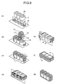
- the unit magnetic cores 11 formed in the inverted U shape are inserted into the protective member 13 through the coil windows 26 as shown in (b) of Fig. 8.
- the protective member 13 is made of insulating material and may be either a single continuous member or a continuous member formed by sticking together a plurality of split parts with adhesive tape.
- step (c) the insertion of the unit magnetic cores 11 is completed as shown in Fig.8.
- the magnetic cores 11, the coils 2 and the protective member 13 are turned so that the surface of said protective member 13 be vertically oriented as shown in Fig.8. Then the joint portions 11j of the inverted U-shaped cores 11 are closed so as to form butted joints in the yoke portion.
- the yoke portions including the joint portions 11j of the magnetic cores 11 are covered by the protective member 13.
- the protective member 13 is folded so as to cover the yoke portions of the magnetic cores 11. No gap is formed between the protective member 13 and the insulating member on the innermost circumference of the coils or the bobbin 23 to prevent amorphous fragments from entering inside the coils 2.
- step (f) as shown in Fig. 8, the yoke portions of magnetic cores 11 are wrapped with the protective member 13, and amorphous fragments are prevented from falling off.
- step (g) as shown in Fig. 8, the unit magnetic cores 11 configured as described above are erected and thereby completed.
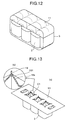
- Fig. 13 discloses an example of a method for sticking the protective member 13 to the insulating member on the innermost circumference of the coil or the bobbin 23.
- five notches C1 corresponding to five legs are formed in the protective member 13 made of rectangular-shaped insulating material.
- (b) is a magnified view of the notch C1.
- a piece of the triangular insulating material emerging in the notch C1 is folded downward to form an angular part 131.
- This angular part 131 is stuck to the innermost circumference of the coil or the bobbin 23 with an adhesive tape 18a, such as a kraft paper tape, so as to form no gap between the angular part 131 and the innermost circumference of the coil or the bobbin 23.
- an adhesive tape 19 it is preferable to stick an adhesive tape 19 to the inside corners of the coil window for reinforcement.
- attaching may be accomplished with glue.
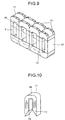
- FIG. 10 One modified example of the method for assembling the magnetic core-coil assembly 3 will be described with reference to Figs. 10 to 12.
- protection members of an insulating material are provided on the upper and lower end surfaces of the coils 2.
- an unit core 11 formed in the inverted U shape by opening the joint portion after annealing is disclosed.
- a reinforcing member 15 for providing strength to the unit core 11 is provided on the innermost circumference, and a reinforcing member 16 of a silicon steel plate is provided on the outermost circumference.
- step (a) on both end surfaces of the coils 2, two protective members 13 are adhered to the insulating members on the innermost circumference of the coils or the bobbins 23. No gap is formed between the protective members 13a, 13b and the insulating members on the innermost circumference of the coils or the bobbins 23.
- Each of the protective members 13a and 13b has the same configuration as the protective member 13 shown in Fig. 13.
- On the protective member 13a, 13b notches C1 for inserting the unit core 11 are also provided as disclosed in Fig.13.
- the unit magnetic cores 11 formed in the inverted U shape are inserted into the protective members 13a, 13b and the coil windows 26 as shown in Fig. 11.
- the protective members 13a, 13b are made of insulating material and may be either a single continuous member or a continuous member formed by sticking together a plurality of split parts with adhesive tape.
- step (c) the insertion of the unit magnetic cores 11 is completed as shown in Fig.11.
- the magnetic cores 11, the coils 2 and the protective members 13a, 13b are turned so that the surface of said protective members 13a, 13b be vertically oriented as shown in Fig. 11. Then the joint portions 11j of the inverted U-shaped cores 11 are closed so as to form butted joints in the yoke portion.
- the yoke portions including the joint portions 11j of the magnetic cores 11 are covered by the protective member 13b.
- the yoke portions without the joint portions 11j of the magnetic cores 11 are covered by the protective member 13a.
- the protective members 13a, 13b are folded so as to cover the yoke portions of the magnetic cores 11. No gap is formed between the protective members 13a, 13b and the insulating members on the innermost circumference of the coils or the bobbins 23 to prevent amorphous fragments from entering inside the coils 2.
- step (f) as shown in Fig. 11, the yoke portions of magnetic cores 11 are wrapped with the protective members 13a, 13b, and amorphous fragments are prevented from falling off.
- step (g) as shown in Fig. 11, the unit magnetic cores 11 configured as described above are erected and thereby completed.
- FIG. 14 shows another method for sticking the protective member 13c to the insulating member on the innermost circumference of the coil or the bobbin 3.
- FIG. 14 As shown in (a) of Fig. 14, in the protective member 13c made of a rectangular insulating material, five notches C2 shaped as a coil window are formed. In Fig. 14, (b) is a magnified view of the notch C2.
- the notches C2 are aligned to the edge part of the coil window.
- the protective members 13c are stuck to the insulating member on the innermost circumference of the coil or the bobbin 23 with an adhesive tape 18b at the notches C2.
- the adhesive tape 18b is a kraft paper tape for instance. No gap is formed between the notches C2 and the innermost circumference of the coil or the bobbin 23.
- the adhesive tape 19 may be stuck to the inside corners of the coil window for reinforcement.
- This invention is not limited to the above-described embodiments. It is also applied to an amorphous wound core transformer having three legs or more, with necessary modification. This invention is also applied to any transformer having a core configuration in which a plurality of unit magnetic cores 11 are arranged in two or more rows in the widthwise direction of the cores. In this case, a plurality of unit cores arranged in rows in the widthwise direction of the cores may be covered with a protecting material row by row, each row being treated collectively, or all the rows may be covered with a protecting material collectively.
- an amorphous metal core transformer capable of improving insulating performance by preventing amorphous fragments from scattering.
- the transformer casing 4 if it is provided with cooling fins 42 outside, can reduce the temperature rise in the transformer.
- smaller watt losses than that in a conventional amorphous metal core transformer resulting in less temperature rise enables to reduce the cooling area by lowering the height of fins or reducing their number.
- the height of the cooling fins 42 may be within the range of 17 mm to 280 mm, the height can be reduced by approximately 20% compared with the conventional amorphous metal core transformer.
- the total surface area of the cooling fins is set to between 0 m 2 and 100 m 2 .
- the total surface area of the cooling fins and the transformer casing is preferably 130 m 2 or less.
- the cooling fins can also serve as ribs to enhance the strength of the transformer casing.
- the transformer casing 4 accommodates the magnetic core-coil assembly 3 and insulating oil inside, and has external terminals 41 outside. Insulating oil, not to contain any gas, should be deaerated beforehand or saturated with nitrogen gas after deaeration.
- the external terminals 41 are connected by the coils 2 and line wires.
- the cooling fins discharge the heat generating from the coils 2 and other internal sources into the atmosphere.
- the present invention is also applied to an amorphous metal core transformer with molded resin coils. Furthermore, it is also applied to a single phase transformer as disclosed in Fig. 15.
- This single phase amorphous metal core transformer has an magnetic core-coil assembly 3, magnetic cores1 and coils 2, and the coils 2 have a primary coil 21, a secondary coil 22, a bobbin 26, and a bobbin spacer 262.
- an insulating member 261 is inserted into a slit in order not to form a one-turn coil.
- magnetic cores and coils can be operated at a relatively low temperature, so that smaller cooling fins can be used, and accordingly the amorphous metal core transformer that facilitates wiring work in coil winding can be obtained.
Landscapes
- Engineering & Computer Science (AREA)
- Power Engineering (AREA)
- Coils Of Transformers For General Uses (AREA)
Claims (8)
- Transformateur à noyaux en métal amorphe, comprenant
une pluralité de noyaux magnétiques enroulés (1) constitués par des feuillards de métal amorphe, et
une pluralité d'enroulements (2), chacun desdits enroulements comportant un enroulement primaire (21) et un enroulement secondaire (22), ledit enroulement primaire (21) employant une matière différente de celle dudit enroulement secondaire (22), chacun desdits enroulements (2) comportant en outre une bobine isolante (26), caractérisé en ce que :ladite bobine isolante (26) a une résistance mécanique supérieure à celle desdits feuillards de métal amorphe. - Transformateur à noyaux en métal amorphe selon la revendication 1, dans lequel
ledit enroulement primaire (21) est constitué par un enroulement conducteur en cuivre, ledit enroulement secondaire (22) est constitué par un enroulement conducteur en aluminium et ledit enroulement secondaire (22) est disposé à l'extérieur dudit enroulement primaire (21) dans la direction radiale dudit enroulement. - Transformateur à noyaux en métal amorphe selon la revendication 2, dans lequel
la densité de courant étalonnée par la résistance électrique dudit enroulement primaire (21) est supérieure à celle dudit enroulement secondaire (22). - Transformateur à noyaux en métal amorphe selon la revendication 2 ou 3, dans lequel
ledit enroulement secondaire (22) a une plus grande longueur que l'enroulement primaire dans la direction axiale de celui-ci. - Transformateur à noyaux en métal amorphe selon l'une quelconque des revendications 1 à 4, dans lequel
ledit enroulement primaire (21) emploie un fil de cuivre rectangulaire et ledit enroulement secondaire (22) emploie un feuillard d'aluminium. - Transformateur à noyaux en métal amorphe selon l'une quelconque des revendications 1 à 5, comprenant en outre un boítier (4) destiné à contenir lesdits noyaux magnétiques (1) et lesdits enroulements (2), ledit boítier (4) étant rempli d'un agent de refroidissement isolant, ledit boítier (4) ayant des ailettes de refroidissement (42) formées de manière à faire saillie depuis une surface dudit boítier (4),
lesdites ailettes de refroidissement (42) faisant saillie depuis ladite surface dudit boítier (4) sur une hauteur de 17 mm à 280 mm, et la superficie totale desdites ailettes de refroidissement (42) et dudit boítier (4) étant de 130 m2 ou moins. - Transformateur à noyaux en métal amorphe selon la revendication 1 à 6, dans lequel
quatre desdits noyaux magnétiques enroulés (1) et trois des enroulements (2) sont assemblés de façon à constituer un transformateur triphasé ayant des noyaux magnétiques à cinq branches. - Transformateur à noyaux en métal amorphes selon la revendication 7, dans lequel
ledit transformateur triphasé a une capacité de 750 kVA ou plus et lesdits trois enroulements (2) sont connectés sous la forme d'un système de montage Δ-Δ.
Applications Claiming Priority (2)
| Application Number | Priority Date | Filing Date | Title |
|---|---|---|---|
| JP10216755A JP2000082625A (ja) | 1998-06-29 | 1998-07-31 | アモルファス鉄心変圧器 |
| JP21675598 | 1998-07-31 |
Publications (2)
| Publication Number | Publication Date |
|---|---|
| EP0977214A1 EP0977214A1 (fr) | 2000-02-02 |
| EP0977214B1 true EP0977214B1 (fr) | 2004-11-24 |
Family
ID=16693420
Family Applications (1)
| Application Number | Title | Priority Date | Filing Date |
|---|---|---|---|
| EP99305944A Expired - Lifetime EP0977214B1 (fr) | 1998-07-31 | 1999-07-27 | Noyau de transformateur en métal amorphe |
Country Status (3)
| Country | Link |
|---|---|
| US (2) | US6750749B2 (fr) |
| EP (1) | EP0977214B1 (fr) |
| DE (1) | DE69922094T2 (fr) |
Families Citing this family (55)
| Publication number | Priority date | Publication date | Assignee | Title |
|---|---|---|---|---|
| US7148782B2 (en) * | 2004-04-26 | 2006-12-12 | Light Engineering, Inc. | Magnetic core for stationary electromagnetic devices |
| EP1787304A1 (fr) * | 2004-08-10 | 2007-05-23 | Crompton Greaves Limited | Transformateur sec compact |
| US7423853B2 (en) * | 2006-06-09 | 2008-09-09 | Schumacher Electric Corporation | Aluminum wound transformer |
| ITVI20060203A1 (it) * | 2006-07-03 | 2008-01-04 | S E A Societa Elettromeccanica | Reattore di potenza per il trasferimento di energia |
| US20080075975A1 (en) * | 2006-09-26 | 2008-03-27 | General Electric Company | Magnetic cores for inductors and transformers and method of manufacture |
| US7397337B2 (en) * | 2006-10-23 | 2008-07-08 | Logah Technology Corp. | Winding base structure of transformer |
| EP2115753A1 (fr) * | 2008-02-22 | 2009-11-11 | Crompton Greaves Limited | Transformateur sec et compact ameliore |
| CN104867661B (zh) * | 2008-09-03 | 2017-10-31 | 株式会社日立产机系统 | 静态设备用卷绕铁芯、非晶变压器及变压器用线圈绕线架 |
| US7830236B2 (en) * | 2008-09-09 | 2010-11-09 | Gm Global Technology Operations, Inc. | DC-DC converter for fuel cell application using hybrid inductor core material |
| US7830235B2 (en) * | 2008-09-09 | 2010-11-09 | Gm Global Technology Operations, Inc. | Inductor array with shared flux return path for a fuel cell boost converter |
| JP4631951B2 (ja) * | 2008-09-19 | 2011-02-16 | パナソニック株式会社 | 巻線コイルと銅線との洗濯機用電気接続手段 |
| US8125304B2 (en) * | 2008-09-30 | 2012-02-28 | Rockwell Automation Technologies, Inc. | Power electronic module with an improved choke and methods of making same |
| ES2404823T3 (es) * | 2009-04-11 | 2013-05-29 | Abb Technology Ag | Transformador de potencia con núcleo amorfo |
| EP2251875A1 (fr) * | 2009-05-16 | 2010-11-17 | ABB Technology AG | Noyau de transformateur |
| CN101937760B (zh) * | 2009-06-30 | 2015-07-01 | 上海市电力公司 | 一种变压器器身 |
| JP5459120B2 (ja) * | 2009-07-31 | 2014-04-02 | 住友電気工業株式会社 | リアクトル、リアクトル用部品、及びコンバータ |
| JP4650755B1 (ja) | 2009-08-31 | 2011-03-16 | 住友電気工業株式会社 | リアクトル |
| US8659381B2 (en) | 2009-08-31 | 2014-02-25 | Sumitomo Electric Industries, Ltd. | Reactor |
| WO2011060547A1 (fr) * | 2009-11-19 | 2011-05-26 | HYDRO-QUéBEC | Ensemble transformateur électrique |
| JP5341058B2 (ja) * | 2010-12-27 | 2013-11-13 | 株式会社日立産機システム | アモルファス変圧器 |
| DK2490229T3 (en) * | 2011-02-16 | 2018-07-16 | Hitachi Industry Equipment Systems Co Ltd | Transformer, amorphous transformer and method of manufacturing the transformer |
| US8572838B2 (en) | 2011-03-02 | 2013-11-05 | Honeywell International Inc. | Methods for fabricating high temperature electromagnetic coil assemblies |
| WO2012155232A1 (fr) | 2011-05-18 | 2012-11-22 | HYDRO-QUéBEC | Appareil de transfert de ruban métallique ferromagnétique et procédé associé |
| JP4800451B1 (ja) * | 2011-06-10 | 2011-10-26 | 株式会社精電製作所 | 高周波トランス |
| US8466767B2 (en) | 2011-07-20 | 2013-06-18 | Honeywell International Inc. | Electromagnetic coil assemblies having tapered crimp joints and methods for the production thereof |
| US8860541B2 (en) | 2011-10-18 | 2014-10-14 | Honeywell International Inc. | Electromagnetic coil assemblies having braided lead wires and methods for the manufacture thereof |
| JP5676414B2 (ja) | 2011-11-01 | 2015-02-25 | 株式会社日立産機システム | アモルファス鉄心変圧器 |
| CN103093942B (zh) * | 2011-11-01 | 2016-03-09 | 株式会社日立产机系统 | 非晶铁芯变压器 |
| US9076581B2 (en) | 2012-04-30 | 2015-07-07 | Honeywell International Inc. | Method for manufacturing high temperature electromagnetic coil assemblies including brazed braided lead wires |
| US8754735B2 (en) | 2012-04-30 | 2014-06-17 | Honeywell International Inc. | High temperature electromagnetic coil assemblies including braided lead wires and methods for the fabrication thereof |
| JP2013247208A (ja) * | 2012-05-25 | 2013-12-09 | Hitachi Industrial Equipment Systems Co Ltd | 巻鉄心スコット変圧器 |
| JP6045839B2 (ja) * | 2012-07-27 | 2016-12-14 | 株式会社日立産機システム | アモルファス鉄心変圧器の製造方法 |
| CN104937680B (zh) * | 2012-10-19 | 2017-04-26 | 三菱电机株式会社 | 逆变器装置、变压器及变压器的制造方法 |
| US9027228B2 (en) | 2012-11-29 | 2015-05-12 | Honeywell International Inc. | Method for manufacturing electromagnetic coil assemblies |
| US9722464B2 (en) | 2013-03-13 | 2017-08-01 | Honeywell International Inc. | Gas turbine engine actuation systems including high temperature actuators and methods for the manufacture thereof |
| KR101365393B1 (ko) * | 2013-03-13 | 2014-02-20 | 엘에스산전 주식회사 | 전기 자동차용 변압기 모듈 |
| CN205196988U (zh) * | 2013-06-17 | 2016-05-04 | 吉瑞高新科技股份有限公司 | 电子烟 |
| US9620280B2 (en) | 2014-01-06 | 2017-04-11 | William Alek | Energy management system |
| TWI579871B (zh) * | 2015-07-10 | 2017-04-21 | yu-qing Zhuang | Transformer E, I type silicon steel sheet stamping method |
| CN109074943B (zh) * | 2016-04-19 | 2021-02-02 | 株式会社日立制作所 | 变压器 |
| CN105957697A (zh) * | 2016-07-27 | 2016-09-21 | 吴江变压器有限公司 | 一种抗短路能力高的非晶合金变压器绕组结构 |
| JP6727142B2 (ja) * | 2017-01-13 | 2020-07-22 | 株式会社日立製作所 | 静止誘導電器 |
| CN111373496A (zh) * | 2017-11-08 | 2020-07-03 | 三菱电机株式会社 | 变压器以及电力转换装置 |
| DE102017222904A1 (de) * | 2017-12-15 | 2019-06-19 | Siemens Aktiengesellschaft | Elektrisches Gerät mit innerer Umwälzeinrichtung |
| DE102017222946A1 (de) * | 2017-12-15 | 2019-06-19 | Siemens Aktiengesellschaft | Wärmegedämmtes Radiatorenglied |
| US12255009B2 (en) * | 2018-05-16 | 2025-03-18 | Solaredge Technologies Ltd. | Partially-conducting transformer bobbin |
| US11289981B2 (en) * | 2018-08-17 | 2022-03-29 | Tai-Her Yang | Frame device of iron core of static electrical machine having outwardly-extended heat dissipation fins and/or heat dissipation hole |
| KR102139004B1 (ko) | 2019-04-02 | 2020-07-28 | 한국전력공사 | 자속 보조용 페라이트 코어를 이용한 용량 가변형 변압기 구조체 및 그 제조 방법 |
| KR102131584B1 (ko) | 2019-04-02 | 2020-07-09 | 한국전력공사 | 변압기 코어부의 모서리 포화 저감 구조체 및 그 제조 방법 |
| KR102136026B1 (ko) | 2019-04-03 | 2020-07-20 | 한국전력공사 | 자속 보조용 페라이트 코어를 이용한 용량 가변형 변압기 구조체 결합구조 및 그 제조 방법 |
| EP3916742B1 (fr) * | 2020-05-27 | 2025-03-19 | Hitachi Energy Ltd | Modification de l'isolation d'un transformateur |
| KR102455751B1 (ko) | 2021-11-29 | 2022-10-17 | 순천대학교 산학협력단 | E형 철심을 이용한 공극 가변형 변압기 구조체 및 이를 이용하는 이용방법 |
| KR102455726B1 (ko) | 2021-12-08 | 2022-10-17 | 순천대학교 산학협력단 | E형 철심을 이용한 공극 가변형 변압기 구조체 및 그 이용방법 |
| JP7624937B2 (ja) * | 2022-01-21 | 2025-01-31 | 株式会社日立産機システム | 変圧器 |
| US20230290565A1 (en) * | 2022-03-10 | 2023-09-14 | Exxelia | Electric transformer with an increased total leakage impedance |
Family Cites Families (20)
| Publication number | Priority date | Publication date | Assignee | Title |
|---|---|---|---|---|
| US3200357A (en) * | 1962-08-23 | 1965-08-10 | Porter Co Inc H K | Transformer coil construction |
| US3464043A (en) * | 1967-10-16 | 1969-08-26 | Allis Chalmers Mfg Co | Conductor strip transformer winding having improved short circuit strength |
| CA898921A (en) * | 1968-04-11 | 1972-04-25 | Trench Electric Limited | Metalized encapsulated coil and method of making the same |
| US3659239A (en) * | 1970-03-12 | 1972-04-25 | Louis L Marton | Power transformer incorporating improved heat dissipation means |
| JPS5134499Y2 (fr) * | 1971-07-29 | 1976-08-26 | ||
| US4327311A (en) * | 1979-08-31 | 1982-04-27 | Frequency, Technology, Inc. | Inductor-capacitor impedance devices and method of making the same |
| US4368407A (en) * | 1979-08-31 | 1983-01-11 | Frequency Technology, Inc. | Inductor-capacitor impedance devices and method of making the same |
| FR2518306B1 (fr) * | 1981-12-11 | 1986-11-28 | Transfix Soc Nouv | Transformateur electrique et procede pour sa fabrication |
| US4523169A (en) * | 1983-07-11 | 1985-06-11 | General Electric Company | Dry type transformer having improved ducting |
| JPS60178609A (ja) * | 1984-02-24 | 1985-09-12 | Tsutomu Yagi | 試験用変圧器 |
| US4609900A (en) * | 1984-06-26 | 1986-09-02 | Bruno Bachhofer | High-voltage transformer with liquid cooling |
| JPH04155907A (ja) * | 1990-10-19 | 1992-05-28 | Murata Mfg Co Ltd | 変圧器 |
| US5225630A (en) * | 1991-06-18 | 1993-07-06 | Cooper Power Systems, Inc. | Transformer assembly having cooling fins and method of providing same |
| JPH06163283A (ja) * | 1992-11-24 | 1994-06-10 | Toshiba Corp | 変圧器 |
| JPH0831667A (ja) * | 1994-07-11 | 1996-02-02 | Hitachi Ltd | アモルファス鉄心変圧器とその製造方法 |
| CA2180992C (fr) * | 1995-07-18 | 1999-05-18 | Timothy M. Shafer | Bobine d'induction a courant eleve et methode de fabrication |
| JPH09254494A (ja) | 1996-03-19 | 1997-09-30 | Pfu Ltd | シート媒体読み/書き装置の実装構造 |
| US5889373A (en) * | 1996-12-30 | 1999-03-30 | General Electric Company | Fluorescent lamp ballast with current feedback using a dual-function magnetic device |
| JP3317877B2 (ja) | 1997-06-06 | 2002-08-26 | 株式会社日立製作所 | アモルファス巻鉄心変圧器 |
| TW371768B (en) * | 1997-06-06 | 1999-10-11 | Hitachi Ltd | Amorphous transformer |
-
1999
- 1999-07-27 DE DE69922094T patent/DE69922094T2/de not_active Expired - Lifetime
- 1999-07-27 EP EP99305944A patent/EP0977214B1/fr not_active Expired - Lifetime
- 1999-07-30 US US09/363,836 patent/US6750749B2/en not_active Expired - Fee Related
-
2001
- 2001-04-04 US US09/825,339 patent/US7034648B2/en not_active Expired - Fee Related
Also Published As
| Publication number | Publication date |
|---|---|
| DE69922094T2 (de) | 2005-12-01 |
| US20020057180A1 (en) | 2002-05-16 |
| US7034648B2 (en) | 2006-04-25 |
| EP0977214A1 (fr) | 2000-02-02 |
| US6750749B2 (en) | 2004-06-15 |
| DE69922094D1 (de) | 2004-12-30 |
| US20010033216A1 (en) | 2001-10-25 |
Similar Documents
| Publication | Publication Date | Title |
|---|---|---|
| EP0977214B1 (fr) | Noyau de transformateur en métal amorphe | |
| US9601256B2 (en) | Wound iron core for static apparatus, amorphous transformer and coil winding frame for transformer | |
| US6005468A (en) | Amorphous transformer | |
| EP1056101A2 (fr) | Transformateur haute tension avec nervures de refroidissement | |
| JPS62222614A (ja) | 変圧器用珪素鋼−非晶質鋼複合鉄心 | |
| JP2000223320A (ja) | 大電流用トランス | |
| US9601255B2 (en) | Amorphous core transformer | |
| US7271696B2 (en) | Two part transformer core, transformer and method of manufacture | |
| JP2000082625A (ja) | アモルファス鉄心変圧器 | |
| JP3317877B2 (ja) | アモルファス巻鉄心変圧器 | |
| US4489298A (en) | Insulating structure for magnetic coils | |
| US4906960A (en) | Distribution transformer with coiled magnetic circuit | |
| JP4358119B2 (ja) | アモルファス鉄心変圧器 | |
| US4859978A (en) | High-voltage windings for shell-form power transformers | |
| US4907339A (en) | Method of construction of a distribution transformer having a coiled magnetic circuit | |
| RU2144229C1 (ru) | Трехфазный симметричный трансформатор | |
| JP3995869B2 (ja) | 変圧器 | |
| JP2022112780A (ja) | 静止誘導機器 | |
| JP2001230134A (ja) | 外鉄型リアクトル及び外鉄型リアクトル用鉄心の組立方法 | |
| KR101427633B1 (ko) | 전력 트랜스포머 | |
| JP2924274B2 (ja) | 円板巻線の製造方法 | |
| JP2003347127A (ja) | 外鉄型絶縁変圧器 | |
| JPH10340816A (ja) | アモルファス巻鉄心変圧器 | |
| JPH0786059A (ja) | コンバータトランス | |
| JP2000208338A (ja) | 外鉄形電磁誘導機器 |
Legal Events
| Date | Code | Title | Description |
|---|---|---|---|
| PUAI | Public reference made under article 153(3) epc to a published international application that has entered the european phase |
Free format text: ORIGINAL CODE: 0009012 |
|
| 17P | Request for examination filed |
Effective date: 19990816 |
|
| AK | Designated contracting states |
Kind code of ref document: A1 Designated state(s): DE FR GB IT |
|
| AX | Request for extension of the european patent |
Free format text: AL;LT;LV;MK;RO;SI |
|
| AKX | Designation fees paid |
Free format text: DE FR GB IT |
|
| 17Q | First examination report despatched |
Effective date: 20030929 |
|
| GRAP | Despatch of communication of intention to grant a patent |
Free format text: ORIGINAL CODE: EPIDOSNIGR1 |
|
| GRAS | Grant fee paid |
Free format text: ORIGINAL CODE: EPIDOSNIGR3 |
|
| GRAA | (expected) grant |
Free format text: ORIGINAL CODE: 0009210 |
|
| AK | Designated contracting states |
Kind code of ref document: B1 Designated state(s): DE FR GB IT |
|
| PG25 | Lapsed in a contracting state [announced via postgrant information from national office to epo] |
Ref country code: IT Free format text: LAPSE BECAUSE OF FAILURE TO SUBMIT A TRANSLATION OF THE DESCRIPTION OR TO PAY THE FEE WITHIN THE PRESCRIBED TIME-LIMIT;WARNING: LAPSES OF ITALIAN PATENTS WITH EFFECTIVE DATE BEFORE 2007 MAY HAVE OCCURRED AT ANY TIME BEFORE 2007. THE CORRECT EFFECTIVE DATE MAY BE DIFFERENT FROM THE ONE RECORDED. Effective date: 20041124 |
|
| REG | Reference to a national code |
Ref country code: GB Ref legal event code: FG4D |
|
| REF | Corresponds to: |
Ref document number: 69922094 Country of ref document: DE Date of ref document: 20041230 Kind code of ref document: P |
|
| PLBE | No opposition filed within time limit |
Free format text: ORIGINAL CODE: 0009261 |
|
| STAA | Information on the status of an ep patent application or granted ep patent |
Free format text: STATUS: NO OPPOSITION FILED WITHIN TIME LIMIT |
|
| ET | Fr: translation filed | ||
| 26N | No opposition filed |
Effective date: 20050825 |
|
| PGFP | Annual fee paid to national office [announced via postgrant information from national office to epo] |
Ref country code: DE Payment date: 20140724 Year of fee payment: 16 |
|
| PGFP | Annual fee paid to national office [announced via postgrant information from national office to epo] |
Ref country code: FR Payment date: 20140708 Year of fee payment: 16 Ref country code: GB Payment date: 20140723 Year of fee payment: 16 |
|
| REG | Reference to a national code |
Ref country code: DE Ref legal event code: R119 Ref document number: 69922094 Country of ref document: DE |
|
| GBPC | Gb: european patent ceased through non-payment of renewal fee |
Effective date: 20150727 |
|
| PG25 | Lapsed in a contracting state [announced via postgrant information from national office to epo] |
Ref country code: DE Free format text: LAPSE BECAUSE OF NON-PAYMENT OF DUE FEES Effective date: 20160202 Ref country code: GB Free format text: LAPSE BECAUSE OF NON-PAYMENT OF DUE FEES Effective date: 20150727 |
|
| REG | Reference to a national code |
Ref country code: FR Ref legal event code: ST Effective date: 20160331 |
|
| PG25 | Lapsed in a contracting state [announced via postgrant information from national office to epo] |
Ref country code: FR Free format text: LAPSE BECAUSE OF NON-PAYMENT OF DUE FEES Effective date: 20150731 |