EP0977319B1 - Contact femelle pour un connecteur et boîtier correspondant - Google Patents
Contact femelle pour un connecteur et boîtier correspondant Download PDFInfo
- Publication number
- EP0977319B1 EP0977319B1 EP99113384A EP99113384A EP0977319B1 EP 0977319 B1 EP0977319 B1 EP 0977319B1 EP 99113384 A EP99113384 A EP 99113384A EP 99113384 A EP99113384 A EP 99113384A EP 0977319 B1 EP0977319 B1 EP 0977319B1
- Authority
- EP
- European Patent Office
- Prior art keywords
- terminal
- proper
- housing
- leaf spring
- female terminal
- Prior art date
- Legal status (The legal status is an assumption and is not a legal conclusion. Google has not performed a legal analysis and makes no representation as to the accuracy of the status listed.)
- Expired - Lifetime
Links
- 239000003381 stabilizer Substances 0.000 claims description 35
- 238000012360 testing method Methods 0.000 claims description 17
- 239000011324 bead Substances 0.000 claims description 8
- 238000003780 insertion Methods 0.000 description 17
- 230000037431 insertion Effects 0.000 description 17
- 230000003014 reinforcing effect Effects 0.000 description 9
- 238000005452 bending Methods 0.000 description 8
- 239000002184 metal Substances 0.000 description 6
- 238000011161 development Methods 0.000 description 2
- 230000018109 developmental process Effects 0.000 description 2
- 238000010586 diagram Methods 0.000 description 2
- 238000009825 accumulation Methods 0.000 description 1
- 230000015572 biosynthetic process Effects 0.000 description 1
- 239000004020 conductor Substances 0.000 description 1
- 230000007797 corrosion Effects 0.000 description 1
- 238000005260 corrosion Methods 0.000 description 1
- 230000001186 cumulative effect Effects 0.000 description 1
- 230000001419 dependent effect Effects 0.000 description 1
- 239000006185 dispersion Substances 0.000 description 1
- 238000006073 displacement reaction Methods 0.000 description 1
- 230000000694 effects Effects 0.000 description 1
- 238000005516 engineering process Methods 0.000 description 1
- 238000007689 inspection Methods 0.000 description 1
- 238000004519 manufacturing process Methods 0.000 description 1
- 239000000463 material Substances 0.000 description 1
- 230000005405 multipole Effects 0.000 description 1
- 230000007935 neutral effect Effects 0.000 description 1
- 230000003449 preventive effect Effects 0.000 description 1
Images


Classifications
-
- H—ELECTRICITY
- H01—ELECTRIC ELEMENTS
- H01R—ELECTRICALLY-CONDUCTIVE CONNECTIONS; STRUCTURAL ASSOCIATIONS OF A PLURALITY OF MUTUALLY-INSULATED ELECTRICAL CONNECTING ELEMENTS; COUPLING DEVICES; CURRENT COLLECTORS
- H01R13/00—Details of coupling devices of the kinds covered by groups H01R12/70 or H01R24/00 - H01R33/00
- H01R13/46—Bases; Cases
-
- H—ELECTRICITY
- H01—ELECTRIC ELEMENTS
- H01R—ELECTRICALLY-CONDUCTIVE CONNECTIONS; STRUCTURAL ASSOCIATIONS OF A PLURALITY OF MUTUALLY-INSULATED ELECTRICAL CONNECTING ELEMENTS; COUPLING DEVICES; CURRENT COLLECTORS
- H01R13/00—Details of coupling devices of the kinds covered by groups H01R12/70 or H01R24/00 - H01R33/00
- H01R13/02—Contact members
- H01R13/10—Sockets for co-operation with pins or blades
- H01R13/11—Resilient sockets
- H01R13/113—Resilient sockets co-operating with pins or blades having a rectangular transverse section
-
- H—ELECTRICITY
- H01—ELECTRIC ELEMENTS
- H01R—ELECTRICALLY-CONDUCTIVE CONNECTIONS; STRUCTURAL ASSOCIATIONS OF A PLURALITY OF MUTUALLY-INSULATED ELECTRICAL CONNECTING ELEMENTS; COUPLING DEVICES; CURRENT COLLECTORS
- H01R13/00—Details of coupling devices of the kinds covered by groups H01R12/70 or H01R24/00 - H01R33/00
- H01R13/40—Securing contact members in or to a base or case; Insulating of contact members
- H01R13/42—Securing in a demountable manner
- H01R13/436—Securing a plurality of contact members by one locking piece or operation
- H01R13/4361—Insertion of locking piece perpendicular to direction of contact insertion
- H01R13/4362—Insertion of locking piece perpendicular to direction of contact insertion comprising a temporary and a final locking position
-
- H—ELECTRICITY
- H01—ELECTRIC ELEMENTS
- H01R—ELECTRICALLY-CONDUCTIVE CONNECTIONS; STRUCTURAL ASSOCIATIONS OF A PLURALITY OF MUTUALLY-INSULATED ELECTRICAL CONNECTING ELEMENTS; COUPLING DEVICES; CURRENT COLLECTORS
- H01R43/00—Apparatus or processes specially adapted for manufacturing, assembling, maintaining, or repairing of line connectors or current collectors or for joining electric conductors
- H01R43/16—Apparatus or processes specially adapted for manufacturing, assembling, maintaining, or repairing of line connectors or current collectors or for joining electric conductors for manufacturing contact members, e.g. by punching and by bending
Definitions
- the present invention belongs to a technical field of a connector wherein a female terminal is inserted in a chamber of a housing.
- a connector has been known, as shown in Fig. 12A, wherein through chambers 82, in several rows and columns in the directions of height and width, are formed in a housing 81 in parallel to each other, a female terminal 84 being approximately tubular in the front half and being connected to an electric wire 83 in the back is inserted into and fixed in each of the chambers 82, and male terminals of a counterpart connector are inserted into these female terminals 84 to make mechanical connections as well as electrical connections (refer to, for example, Japanese Patent Publication (unexamined) Hei 8- 106944 corresponding to US-A-5 653 613.
- a port 85 open in the front end of the above mentioned female terminal 84 to receive a male terminal.
- a splicing part 86 is formed in the back of the female terminal 84 to connect an electric wire 83.
- a concave fixing part 87 is formed in an intermediate part of the female terminal 84.
- a hook of a lance 88 that is flexibly formed in a chamber 82 of the bousing 81 fits into this concave fixing part 87 to make a primary fixing of the female terminal 84 to the housing 81.
- a fixing piece 90 of a retainer 89 that is fitted into the housing 81 is set at the back of a stabilizer 91 that is formed on the top of the intermediate part of the female terminal 84 to make a secondary fixing of the female terminal 84 to the housing 81.
- a connection structure between a female terminal of this kind and a male terminal has been disclosed in Japanese Patent Publication (unexamined) Hei 9- 232021.
- a leaf spring 93' is integrally formed inside the terminal proper 94' of a female terminal 84'.
- This leaf spring 93' is blanked out together with the terminal proper 94' of a sheet metal and formed by bending the blank.
- the material and thickness of the sheet metal are selected by considering formability, cos:, etc., it is difficult to secure a sufficient contacting force from the single leaf spring 93'.
- the above-mentioned Japanese Patent Publication (unexamined) Hei 9- 232021 has disclosed a. technology wherein a separate reinforcing leaf spring 95' is blanked out together with the terminal proper 94' and this reinforcing leaf spring 95' is bent on the inner side of the main leaf spring 93' to form double springs and ensure a sufficient contacting force.
- the above- mentioned stabilizer 91 can exhibit a function of preventing so-called inverse insertion; if the female terminal 84 is inserted into the chamber 82 of the housing 81 in an incorrect orientation, for example, upside down, the stabilizer 91 will catch the entrance of the chamber 82 to prevent further insertion. Because of this function, the female terminal 84 and the retainer 89 are brought to a proper positional relationship and the female terminal 84 is fixed by the retainer 89. However, as the stabilizer is to be fixed by a fixing piece 90 of the retainer 89, the stabilizer is provided on the top of the intermediate part of the terminal proper. Accordingly, the front portion of the terminal proper ahead of the stabilizer 91, even if it is inverted upside down, would be inserted. This, in turn, would make the worker forcefully insert the female terminal 84 further, resulting in a damage to the chamber and nearby of the housing 81.
- a test jig having a shape identical to that of a male terminal is inserted into the female terminal.
- the test jig When the test jig is used repeatedly, the jig may be deformed. If such a deformed jig is forced into a female terminal, the leaf spring, etc. will be damaged to cause a trouble.
- a connector is used in combination with a counterpart connector. Compactification of the counterpart connector is also desired. If there is an error in assembling a male terminal in the counterpart connector, the male terminal may be assembled to be slightly slant in relation to the housing. In the worst case, such a male terminal may cause a trouble that it can not be inserted into a female terminal.
- WO 98 18181 A which is considered to represent the most relevant state of the art, discloses a female terminal that is inserted into a chamber of a housing of a connector and receives a male terminal, said female terminal comprising a terminal proper having a tubular front half part that can be inserted into said chamber of the housing, having a port that opens in the front end and receives a male terminal, having a splice part that is in the back and that is connected to an electric wire, and having a fixing part into which a retainer of said housing fits; a leaf spring having a root end that is integral to the front half part of said terminal proper, having a top end that extends forward inside the front half part of said terminal proper, and being to be fixed in the direction of height, and a bead that is formed ahead of a round part of said leaf spring on the top side thereof and has a curved section to increase the flexural rigidity.
- U.S-A 3 083 351 relates to an electrical' receptacle.
- JP 5-135819 A relates to a receptacle contact used for a multipole type electric connector in a compact size and a high density structure, wherein a round part of a spring is bent around an axis lying approximately in the height direction.
- the present invention was made in view of the above-mentioned points.
- a stable and sufficient contacting force shall be ensured by forming a bead and increasing the flexural rigidity of a leaf spring and using only a single leaf spring, to move a contacting part of the leaf spring forward, to reduce the length of insertion of a male terminal and compactify the counter connector; and to increase the tolerance to slant of the male terminal.
- the function of preventing inverse insertion of the female terminal shall be reinforced by shifting the stabilizer forward. Damage to the leaf spring, etc. shall be prevented by making the stabilizer available to a continuity test, etc. of the female terminal. Further, the connector in the direction of height shall be compactified as much as possible by, in addition to using a single leaf spring and shifting the round part backward, flexing a lance in the direction of width.
- a female terminal that is inserted into a chamber of a housing of a connector and receives a male terminal
- said female terminal comprising: a terminal proper having a tubular front half part that can be inserted into said chamber of the housing, having a port that opens in the front end and receives a male terminal, having a splicing part that is in the back and that is connected to an electric wire, and having a fixing part into which a retainer of said housing fits; a leaf spring having a root end that is integral to the front half of said terminal proper, having a top end that extends forward inside the front half part of said terminal proper, and being to be flexed in the direction of height; a stabilizer being erected in the direction of height on the outer side at the front end of said terminal proper, having a face in the direction of width, fitting into a groove formed in the longitudinal direction and advancing beyond a lance that is formed in the groove and being fixed by the lance when said terminal proper is inserted into the chamber of the housing; a terminal
- the stabilizer When an electric wire is connected to the splicing part of the terminal proper and the female terminal is inserted into a chamber of the housing, the stabilizer will fit into the groove of the housing and advance forward beyond the lance of the housing and will be fixed by the lance. This is the primary fixing of the female terminal to the housing. Next, when a retainer is pushed into the housing, the retainer will fit into the fixing part of the terminal proper. This is the secondary fixing of the female terminal to the housing. When a counterpart connector is opposed to the connector and a male terminal of the counterpart connector is inserted into the female terminal, the leaf spring will be pressed to contact the male terminal to make both mechanical connection and electrical connection between the two connectors.
- the flexural rigidity of the leaf spring is greater and a sufficient contacting force is provided without provision of a reinforcing spring.
- the spring constant has no point of infliction, and the contacting force of each product is stabilized.
- the flexural rigidity of the leaf spring is greater, a sufficient contacting force is generated even if a contacting part of the leaf spring is shifted forward close to the port.
- the radius of curvature of the round part can be set larger by extensively using the interior of the front half part of the terminal proper in the direction of height. This prevents generation of cracks in the round part and stabilizes the contacting force.
- the stabilizer is provided at the front end of the terminal proper, if the female terminal is inserted into a chamber of the housing in a wrong orientation, the stabilizer will catch on the entrance of the chamber in the initial stage of insertion. Thus inverse insertion of the female terminal is prevented reliably, and any damage to the housing due to incorrect operation of the worker can be avoided.
- a continuity test, etc. can be made without giving any damage to the leaf spring, etc.As no reinforcing spring is used, the height of the female terminal is lower, and as the round part is in a position beyond the reach of the male terminal and it does not require any space for a male terminal to crawl into beneath the leaf spring, the height of the female terminal can be lowered further.
- the connector can be compactified in the direction of height as much as possible.
- the single leaf spring can stably provide a sufficient contacting force, and the contacting part of the leaf spring can be shifted forward.
- the counterpart connector can be compactified.
- the tolerance to slant of the male terminal is increased and the yield of the connectors can be improved.
- the radius of curvature of the round part can be increased in a position beyond the reach of the male terminal, generation of cracks, etc. in the leaf spring can be prevented to stabilize the contacting force.
- the stabilizer is provided at the front end of the terminal proper, inverse insertion of the female terminal can be prevented reliably. Moreover, the stabilizer can be used in making a continuity test or the like on the female terminal, and this prevents damage to the leaf spring, etc. Use of a single leaf spring, shifting of the round part backward and flexing of the lance in the direction of width allow compactification of the connector in the direction of height as much as possible.
- Fig. 2 through Fig. 6 show a female terminal T of a connector C of the first embodiment.
- Fig. 1, Fig. 10A and Fig. 10B show the connector C wherein this female terminal T is inserted in a housing H.
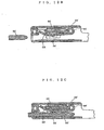
- the female terminal T is provided with a terminal proper 10 having an approximately tubular front half part that can be inserted into a chamber 51 of the housing H, a leaf spring 20 of which root end is integral to the front half of the terminal proper 10, and a stabilizer 30 being on the outer side of the terminal proper 10.
- the front- rear direction is the longitudinal direction.
- it is the direction perpendicular to the paper.
- the direction of height substantially corresponds to the direction of flexing of the top end of the leaf spring 20; for example, in Fig. 3, it is the direction perpendicular to the paper.
- the direction of width substantially corresponds to the direction of width of the top end of the leaf spring 20; for example, in Fig. 2, it is the direction perpendicular to the paper.
- This system of directions is also applied to the housing H.
- the front - rear direction, the height direction and the width direction of the female terminal T that is inserted in the chamber 51 are the front- rear direction, the height direction and the width direction of the chamber 51 of the housing H, respectively.
- a port 11 is opened in the front end of the above- mentioned terminal proper 10 to receive a male terminal TT.
- a splicing part 12 for connecting an electric wire W is provided in the back thereof. This splicing part 12 is formed to have an approximately U- shaped section. Its upper edge portions are bent inward to crimp the conductor of the electric wire W.
- a longitudinally intermediate part of the terminal proper 10 is provided with a fixing part 13 into which a retainer 60 of the housing H is to be fitted. This fixing part 13 is formed into an approximately U- shape when seen from the side. As the upper edges of the fixing part 13 are formed to be lower than the upper wall of the front half part of the terminal proper 10, the retainer 60 can be fitted into the fixing part 13 as shown in Fig. 1.
- the top end of the above-mentioned leaf spring 20 extends forward inside the front half part of the terminal proper 10 and can be flexed in the height direction.
- the top end of the leaf spring 20 will be pressed to contact the male terminal TT.
- a round part 21 that bends around an axis approximately parallel to the front half part into an approximately circular arc in a position beyond the reach of the male terminal TT, is formed.
- a bead 22 that has a curved section to increase the flexural rigidity is formed ahead of the round part 21 of the leaf spring 20.
- bending around an axis approximately parallel to the front half part means bending in such a way that displacement takes place in the direction of height.
- the round part 21 is formed into an approximately circular arc around an axis that is in the front- rear direction of the terminal proper 10.
- Examples of the sectional forms of the above- mentioned beam 22 include approximately U- shaped form, approximately W- shaped form and their inverted forms. What is important is that when the leaf spring 20 is sectioned along a plane in the front- rear direction the moment of inertia of area along a neutral axis passing sidewise in the middle, in the thickness direction, of the leaf spring 20 is greater than that of a flat plate.
- Slits 14, 14 are formed in a portion of terminal proper 10 that is continuous to the round part 21 from both side edges of the round part's root end in the width direction of the terminal proper 10.
- a guide 15 is formed to cover a gap between the top end of the leaf spring 20 and the inner wall of the terminal proper 10. This guide 15 prevents inadvertent insertion of the male terminal TT or a screwdriver for inspection, etc. into the gap.
- the above- mentioned stabilizer 30 will fit into a groove 52 that is formed in the front- rear direction and moves forward beyond a lance 53 that is formed in the groove.
- the stabilizer 30 will reach a position in front of the lance 53 and will be fixed there by the lance 53.
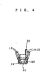
- the stabilizer 30 having a face in the width direction is erected in the height direction at the front end of the terminal proper 10.
- the stabilizer 30 is provided on the upper side of the terminal proper 10.
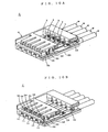
- the above- mentioned housing H comprises a housing proper 50 in which through chambers 51 are formed in the front- rear direction and a retainer 60 that fits into the housing proper 50 and penetrates into the chambers 51.
- the above- mentioned housing proper 50 is provided with grooves 52 that are made in the height direction from the chambers, extend in the front- rear direction and receive the stabilizers 30, lances 53 that are formed in respective grooves to be flexed in the width direction of the chambers 51 and fix the stabilizers 30 by the front sides, and testing windows 54 that allow access to the grooves 52 in front of the lances 53 from the front side.
- the above- mentioned grooves 52 are formed upward from the chambers 51.
- the exemplifying connector C has a single row of parallel chambers 51 arranged in the width direction. However, as shown in Fig. 12A, such rows of chambers 51 may be arranged in several columns in the height direction.
- the above- mentioned female terminal T is formed from a single sheet metal. As shown in Fig. 9, plural female terminals T, T ... in a developed form, with a runner connecting them together, are blanked out of a sheet metal. Next, various parts are bent to form the female terminals T, T ... into the final shape. After that, the respective female terminals T are separated from the runner N.
- each leaf spring 20 will press to contact a male terminal TT to make mechanical connections and electric connections between both connectors C, CC (the state shown in Fig. 1).
- the flexural rigidity of the leaf spring 20 is greater and a sufficient contacting force is provided without provision of a reinforcing spring.
- the spring constant has no point of inflection, and the contacting force of each product is stabilized.
- the flexural rigidity of the leaf spring 20 is greater, a sufficient contacting force is generated even if a contacting part of the leaf spring 20 is shifted forward close to the port.
- the length of insertion of the male terminal TT is shortened, and in turn, the housing HH of the counterpart connector CC that contains the male terminal TT is shortened and compactified and the tolerance to slant of the male terminal TT is also increased.
- the yield of connectors CC can be improved.
- the radius of curvature of the round part 21 can be set larger by extensively using the interior of the front half part of the terminal proper in the height direction. This prevents generation of cracks in the round part 21 and stabilizes the contacting force.
- the stabilizer 30 As the stabilizer 30 is provided at the top end of the terminal proper 10, if the female terminal T is inserted into a chamber 51 of the housing H in a wrong orientation, the stabilizer 30 will catch on the entrance of the chamber 51 in the initial stage of insertion. Thus inverse insertion of the female terminal T is prevented reliably, and any damage to the housing H due to incorrect operation of the worker can be avoided. Furthermore, as the test window 54 that directly leads to the stabilizer 30 is opened in the front of the housing H, when a test jig of which shape is identical to that of the male terminal TT is inserted into the test window 54, the test jig will contact the stabilizer 30. Thus a continuity test, etc. can be made without giving any damage to the leaf spring, etc.
- the height of the female terminal T is lowered, and as the round part 21 is in a position beyond the reach of the male terminal TT and it does not require any space for the male terminal TT to crawl into beneath the leaf spring 20, the height of the female terminal T can be lowered further.
- the lance 53 of the housing H is flexed in the direction of width by the stabilizer 30 having a face set in the direction of width, there is no need of providing a space for flexing in the direction of height of the housing and the height can be reduced. As a result, the connector C can be compactified in the direction of height as much as possible.
- the connector C wherein chambers 51 are arranged in the direction of height, several female terminals T are arranged in succession in the direction of height, and the number of walls between chambers 51 is larger.
- the connector C can be compactified significantly in the direction of height. Because of this, the connector C is suitable as a connector for automobiles in which higher space utility is rigorously demanded.
- the stabilizer 30 is provided on the lower side of the terminal proper 10
- the groove 52 is made downward from the chamber 51 and the lance 53 is provided to flex in the direction of width of the chamber 51
- the connector C can be compactified in the direction of height just like the above- mentioned embodiment.
- the female terminal T When the female terminal T is to be blanked out of a sheet metal, it is necessary to make sure that the respective parts do not interfere with each other in the developed form. These restraints may impair the degree of freedom of design.
- the round part 21 is bent into an approximately circular arc around an axis that is in the front- rear direction of the terminal proper 10 as is the case of the above- mentioned first embodiment, as shown in Fig. 9, if the female terminal T is formed from a single sheet metal, the leaf spring 20 and the splicing part 12 in the developed form of the female terminal T hardly interfere with each other.
- the degree of freedom of design is enhanced.
- Connectors of this kind may undergo wear caused by microsliding.
- a pair of connectors being connected with each other are subjected to temperature changes, they will undergo thermal deformation.
- the contacting surfaces of the female terminal and the male terminal slip relative to each other.
- oxide films that are formed near the contacting surfaces will peel eventually. This is microsliding wear. Accumulation of this oxide film eventually causes imperfect contact.
- one way is to increase the contacting force of the leaf spring so that the slip hardly occurs. This, however, demands a large force in connecting the connectors together. It will be hard to use connectors having a large number of terminals.
- the force required for connecting the connector C can be set adequately and workability can be enhanced. Moreover, a connector C with a large number of terminals can be set.
- This second embodiment differs from the above- mentioned first embodiment only in the configuration of the round part of the leaf spring, and other configurations are identical. Accordingly, identical marks are given to members that exhibit identical functions of the members of the first embodiment. The description of the first embodiment except a portion concerning the configuration of the round part of the leaf spring is quoted intact as the description of the configuration of the second embodiment.
- the round part 21 of the second embodiment is formed by bending a portion into an approximately circular arc around an axis that is in the right- left direction of the terminal proper 10, and slits 14, 14 are not formed.
- the present invention includes an embodiment that is the first embodiment except no slits are formed. Further the second embodiment can be provided with formation of slits.
- the round part 21 is formed by bending into an approximately circular arc around an axis that is in the front- rear direction of the terminal proper 10
- the round part 21 is formed by bending into an approximately circular arc around an axis that is in the left- right direction of the terminal proper 10
- the present invention includes only first embodiments having a round part (21) that is formed at the root end of said leaf spring (20) and bent around an axis lying approximately in said longitudinal direction of said front half part into an approximately circular arc in a position beyond the reach of said male terminal (TT), wherein the radius of curvature of the round part (21) extensively uses the interior of the front half part of the terminal proper (10) in the height direction.
Landscapes
- Connector Housings Or Holding Contact Members (AREA)
Claims (3)
- Borne femelle (T) pour un connecteur (C) comprenant :un terminal propre (10) ayantune demie partie avant tubulaire se prolongeant dans le sens longitudinal depuis une extrémité avant vers une extrémité arrière et allant vers le haut et dans la largeur, respectivement, lesdites directions étant à la fois perpendiculaires au dit sens longitudinal et étant perpendiculaires l'un à l'autre, dont la demie partie avant peut être insérée dans une chambre (51) d'un logement (H) dudit connecteur (C) pour obtenir un état inséré,une ouverture (11) qui s'ouvre sur l'extrémité avant pour, dans un état inséré, recevoir une borne mâle (TT),un élément d'épissurage (12) qui se trouve sur l'extrémité arrière et qui doit être raccordé à un fil électrique (W), etun élément de fixation (13) dans lequel, en état inséré, un dispositif de retenue (60) dudit logement (H) vient s'adapter :un ressort à lames (20) ayant
une extrémité racine intégrée dans la demie partie avant de ladite borne propre (10), et
une extrémité supérieure se prolongeant à l'intérieur de la demie partie avant de ladite borne propre (10) vers l'extrémité avant dans le sens longitudinal et devant être fléchie dans le sens de la hauteur ;
et
une nervure (22) formée en avant de la partie ronde (21) dudit ressort à lames (20) du côté de son extrémité supérieure et présentant une section incurvée pour augmenter la rigidité à la flexion ;
caractérisée par le fait que
un stabilisateur (30) étant érigé dans le sens de la hauteur sur le côté extérieur de l'extrémité avant de ladite borne propre (10), dont une face, dans le sens de la largeur, s'insère dans une rainure (52) formée dans le sens longitudinal et avançant au-delà d'un crevé (53) formé dans la rainure (52) et fixé par le crevé (53) dans ledit état inséré ;
la partie arrondie (21) formée au niveau de l'extrémité racine dudit ressort à lames (20) et recourbée autour d'un d'axe reposant approximativement dans ledit sens longitudinal de ladite demie partie avant selon un arc approximativement circulaire dans une position dépassant la portée de ladite borne mâle (TT), dans laquelle le rayon de courbure de la partie arrondie (21) utilise de façon extensive l'intérieur de la demie partie avant de la borne propre (10) dans le sens de la hauteur. - Borne femelle (T) selon la revendication 1, caractérisée par le fait que des fentes (14) sont formées dans une partie de la borne propre (10) qui est continue par rapport à la partie arrondie (21) des deux bords latéraux de l'extrémité racine de la partie arrondie (21), dans le sens de la largeur de la borne propre (10).
- Combinaison d'un logement (H) d'un connecteur (C) et d'une borne femelle (T) selon la revendication 1 ou 2, caractérisée par
un logement propre (50) ayant
lesdites chambres (51) comme chambres traversantes formées dans le sens longitudinal ,
lesdites rainures (52) faites dans le sens de la hauteur desdites chambres (51), se prolongeant dans le sens longitudinal et recevant lesdits stabilisateurs (30),
lesdits crevés (53) formés dans lesdites rainures (52) pour qu'elles soient fléchies dans le sens de la largeur desdites chambres (51) et pour fixer lesdits stabilisateurs (30) par l'extrémité avant, et
des fenêtres d'essai (54) permettant l'accès aux rainures (52) sur l'avant des crevés (53) depuis la partie avant ; et
ledit dispositif de retenue (60) s'adaptant dans ledit logement propre (50) et pénétrant dans lesdites chambres (51).
Applications Claiming Priority (2)
| Application Number | Priority Date | Filing Date | Title |
|---|---|---|---|
| JP21975398A JP3224369B2 (ja) | 1998-07-16 | 1998-07-16 | コネクタの端子及びハウジング |
| JP21975398 | 1998-07-16 |
Publications (3)
| Publication Number | Publication Date |
|---|---|
| EP0977319A2 EP0977319A2 (fr) | 2000-02-02 |
| EP0977319A3 EP0977319A3 (fr) | 2000-12-20 |
| EP0977319B1 true EP0977319B1 (fr) | 2006-05-03 |
Family
ID=16740470
Family Applications (1)
| Application Number | Title | Priority Date | Filing Date |
|---|---|---|---|
| EP99113384A Expired - Lifetime EP0977319B1 (fr) | 1998-07-16 | 1999-07-10 | Contact femelle pour un connecteur et boîtier correspondant |
Country Status (5)
| Country | Link |
|---|---|
| US (1) | US6174208B1 (fr) |
| EP (1) | EP0977319B1 (fr) |
| JP (1) | JP3224369B2 (fr) |
| KR (1) | KR100579653B1 (fr) |
| DE (1) | DE69931110T2 (fr) |
Families Citing this family (26)
| Publication number | Priority date | Publication date | Assignee | Title |
|---|---|---|---|---|
| JP3620786B2 (ja) * | 2000-01-24 | 2005-02-16 | 矢崎総業株式会社 | 端子金具 |
| US6398597B1 (en) * | 2001-02-09 | 2002-06-04 | Hon Hai Precision Ind. Co., Ltd. | Receptacle contact of a cable assembly and the cable assembly using the same |
| DE60218094T2 (de) * | 2001-09-07 | 2007-11-29 | Sumitomo Wiring Systems, Ltd., Yokkaichi | Anschlusskontakt, damit ausgestatteter Steckverbinder und Herstellungsverfahren des Anschlusskontaktes |
| JP3763574B2 (ja) * | 2003-03-14 | 2006-04-05 | 日本航空電子工業株式会社 | コネクタ |
| US6905376B2 (en) * | 2003-04-15 | 2005-06-14 | J.S.T. Mfg. Co., Ltd. | Terminal |
| US7229324B2 (en) | 2004-04-06 | 2007-06-12 | Fci Sa | High speed receptacle connector part |
| FR2869161B1 (fr) * | 2004-04-19 | 2007-04-20 | Fci Sa | Contact electrique, et partie de connecteur electrique comprenant un tel contact |
| KR100808951B1 (ko) * | 2006-12-14 | 2008-03-04 | 한국단자공업 주식회사 | 저삽입력 커넥터 |
| JP2008293722A (ja) * | 2007-05-23 | 2008-12-04 | Sumitomo Wiring Syst Ltd | コネクタ |
| KR100897376B1 (ko) * | 2007-06-25 | 2009-05-14 | 한국단자공업 주식회사 | 커넥터 |
| TWD130276S1 (zh) * | 2008-04-08 | 2009-08-11 | 股份有限公司 | 接點元件 |
| JP5285985B2 (ja) * | 2008-07-17 | 2013-09-11 | 矢崎総業株式会社 | 雌型端子金具 |
| USD603806S1 (en) * | 2008-11-05 | 2009-11-10 | Japan Aviation Electronics Industry Limited | Electrical connection terminal |
| US8974256B2 (en) * | 2012-04-26 | 2015-03-10 | Sumitomo Wiring Systems, Ltd. | Terminal fitting and production method therefor |
| JP6027937B2 (ja) * | 2013-04-08 | 2016-11-16 | 矢崎総業株式会社 | コネクタ |
| EP3005485B1 (fr) * | 2013-06-07 | 2018-01-03 | FCI Asia Pte. Ltd. | Connecteur pour cable |
| DE102013222941A1 (de) * | 2013-11-12 | 2015-05-13 | Zf Friedrichshafen Ag | Steckverbinder |
| CN105934855B (zh) | 2013-12-03 | 2020-01-17 | 富加宜(亚洲)私人有限公司 | 连接器和用于这种连接器的插针接收接触件 |
| US20150275952A1 (en) * | 2014-03-25 | 2015-10-01 | Fritz Stepper Gmbh & Co. Kg | Plug-on part for a plug connector |
| US9437991B2 (en) * | 2014-07-10 | 2016-09-06 | Schneider Electric USA, Inc. | Load center bus having integral stabs with formed shapes |
| US9472885B2 (en) * | 2014-12-08 | 2016-10-18 | Delphi Technologies, Inc. | Electrical connector assembly with low terminal insertion force |
| JP1599728S (fr) * | 2017-07-07 | 2018-03-19 | ||
| CN109411934B (zh) * | 2017-08-16 | 2021-11-19 | 富士康(昆山)电脑接插件有限公司 | 电连接器 |
| US10431912B2 (en) * | 2017-09-29 | 2019-10-01 | Intel Corporation | CPU socket contact for improving bandwidth throughput |
| WO2019178520A1 (fr) | 2018-03-16 | 2019-09-19 | Fci Usa Llc | Connecteurs électriques à haute densité |
| CN111370381B (zh) * | 2020-03-27 | 2022-04-01 | 广东芯聚能半导体有限公司 | 连接组件、功率半导体及适用于功率半导体的连接方法 |
Citations (1)
| Publication number | Priority date | Publication date | Assignee | Title |
|---|---|---|---|---|
| JPH05135819A (ja) * | 1991-11-12 | 1993-06-01 | Amp Japan Ltd | リセプタクルコンタクト |
Family Cites Families (8)
| Publication number | Priority date | Publication date | Assignee | Title |
|---|---|---|---|---|
| US3083351A (en) * | 1961-04-10 | 1963-03-26 | Jr Auker J Nielsen | Electrical receptacle |
| JP2767732B2 (ja) * | 1993-01-19 | 1998-06-18 | 矢崎総業株式会社 | 接続端子の係止解除機構 |
| JP2581476Y2 (ja) * | 1993-04-13 | 1998-09-21 | 住友電装株式会社 | コネクタ |
| JPH08106944A (ja) * | 1994-10-03 | 1996-04-23 | Tokai Rika Co Ltd | 電気コネクタ及び同電気コネクタのハウジング |
| JPH0955246A (ja) | 1995-08-15 | 1997-02-25 | Amp Japan Ltd | 電気端子 |
| JPH09232021A (ja) | 1996-02-20 | 1997-09-05 | Amp Japan Ltd | 雌型電気端子 |
| JP3062928B2 (ja) * | 1996-04-26 | 2000-07-12 | 日本航空電子工業株式会社 | コンタクト |
| EP0932917B1 (fr) * | 1996-10-17 | 2000-05-24 | The Whitaker Corporation | Connecteur electrique pourvu d'un boitier ainsi que d'un contact |
-
1998
- 1998-07-16 JP JP21975398A patent/JP3224369B2/ja not_active Expired - Lifetime
-
1999
- 1999-07-07 US US09/348,393 patent/US6174208B1/en not_active Expired - Lifetime
- 1999-07-10 EP EP99113384A patent/EP0977319B1/fr not_active Expired - Lifetime
- 1999-07-10 DE DE69931110T patent/DE69931110T2/de not_active Expired - Lifetime
- 1999-07-16 KR KR1019990028888A patent/KR100579653B1/ko not_active Expired - Fee Related
Patent Citations (1)
| Publication number | Priority date | Publication date | Assignee | Title |
|---|---|---|---|---|
| JPH05135819A (ja) * | 1991-11-12 | 1993-06-01 | Amp Japan Ltd | リセプタクルコンタクト |
Also Published As
| Publication number | Publication date |
|---|---|
| EP0977319A3 (fr) | 2000-12-20 |
| KR100579653B1 (ko) | 2006-05-15 |
| JP3224369B2 (ja) | 2001-10-29 |
| EP0977319A2 (fr) | 2000-02-02 |
| KR20000011776A (ko) | 2000-02-25 |
| JP2000036350A (ja) | 2000-02-02 |
| DE69931110T2 (de) | 2006-11-23 |
| DE69931110D1 (de) | 2006-06-08 |
| US6174208B1 (en) | 2001-01-16 |
Similar Documents
| Publication | Publication Date | Title |
|---|---|---|
| EP0977319B1 (fr) | Contact femelle pour un connecteur et boîtier correspondant | |
| EP0986141B1 (fr) | Borne femelle pour un connecteur et sa carcasse | |
| EP0932917B1 (fr) | Connecteur electrique pourvu d'un boitier ainsi que d'un contact | |
| EP1923962B1 (fr) | Connecteur et son procédé de pré-assemblage | |
| US7300319B2 (en) | Electrical contact | |
| EP1936749B1 (fr) | Organe de contact, connecteur et procédé de fabrication | |
| US6679738B2 (en) | Female terminal | |
| EP1271705B1 (fr) | Connecteur ayant un limiteur d' ouvrage pour un dispositif de retenue | |
| EP1990867A2 (fr) | Contact électrique | |
| US10910754B2 (en) | Stacked connector | |
| US10819060B2 (en) | Stacked connector | |
| US6585544B2 (en) | Terminal fitting | |
| EP0981184A1 (fr) | Boítier d'un connecteur ayant un dipositif de retenue articulé | |
| US4717361A (en) | Contact for connector | |
| US6589080B2 (en) | Terminal fitting and a connector | |
| CN112909608A (zh) | 端子零件 | |
| JP3784450B2 (ja) | リセプタクル型端子 | |
| US12142866B2 (en) | Terminal fitting and connector | |
| JP4520874B2 (ja) | 雌端子及びコネクタ | |
| US11990700B2 (en) | Connector with front mask | |
| JP7418305B2 (ja) | 電線圧接構造 | |
| JP7567719B2 (ja) | コネクタ | |
| TWI752408B (zh) | 連接器及端子 | |
| US20180151972A1 (en) | Female electrical terminal | |
| US20240380150A1 (en) | Terminal fitting connection structure and joint connector |
Legal Events
| Date | Code | Title | Description |
|---|---|---|---|
| PUAI | Public reference made under article 153(3) epc to a published international application that has entered the european phase |
Free format text: ORIGINAL CODE: 0009012 |
|
| AK | Designated contracting states |
Kind code of ref document: A2 Designated state(s): DE FR GB |
|
| AX | Request for extension of the european patent |
Free format text: AL;LT;LV;MK;RO;SI |
|
| RIN1 | Information on inventor provided before grant (corrected) |
Inventor name: CHEN, PING, JAPAN SOLDERLESS TERM. MFG. CO., LTD. |
|
| PUAL | Search report despatched |
Free format text: ORIGINAL CODE: 0009013 |
|
| AK | Designated contracting states |
Kind code of ref document: A3 Designated state(s): AT BE CH CY DE DK ES FI FR GB GR IE IT LI LU MC NL PT SE |
|
| AX | Request for extension of the european patent |
Free format text: AL;LT;LV;MK;RO;SI |
|
| RIC1 | Information provided on ipc code assigned before grant |
Free format text: 7H 01R 13/436 A, 7H 01R 13/115 B, 7H 01R 4/18 B, 7H 01R 13/422 B |
|
| 17P | Request for examination filed |
Effective date: 20010525 |
|
| AKX | Designation fees paid |
Free format text: DE FR GB |
|
| 17Q | First examination report despatched |
Effective date: 20020917 |
|
| GRAP | Despatch of communication of intention to grant a patent |
Free format text: ORIGINAL CODE: EPIDOSNIGR1 |
|
| GRAS | Grant fee paid |
Free format text: ORIGINAL CODE: EPIDOSNIGR3 |
|
| GRAA | (expected) grant |
Free format text: ORIGINAL CODE: 0009210 |
|
| AK | Designated contracting states |
Kind code of ref document: B1 Designated state(s): DE FR GB |
|
| REG | Reference to a national code |
Ref country code: GB Ref legal event code: FG4D |
|
| REF | Corresponds to: |
Ref document number: 69931110 Country of ref document: DE Date of ref document: 20060608 Kind code of ref document: P |
|
| ET | Fr: translation filed | ||
| PLBE | No opposition filed within time limit |
Free format text: ORIGINAL CODE: 0009261 |
|
| STAA | Information on the status of an ep patent application or granted ep patent |
Free format text: STATUS: NO OPPOSITION FILED WITHIN TIME LIMIT |
|
| 26N | No opposition filed |
Effective date: 20070206 |
|
| PGFP | Annual fee paid to national office [announced via postgrant information from national office to epo] |
Ref country code: FR Payment date: 20100802 Year of fee payment: 12 Ref country code: DE Payment date: 20100715 Year of fee payment: 12 |
|
| PGFP | Annual fee paid to national office [announced via postgrant information from national office to epo] |
Ref country code: GB Payment date: 20100726 Year of fee payment: 12 |
|
| GBPC | Gb: european patent ceased through non-payment of renewal fee |
Effective date: 20110710 |
|
| REG | Reference to a national code |
Ref country code: FR Ref legal event code: ST Effective date: 20120330 |
|
| PG25 | Lapsed in a contracting state [announced via postgrant information from national office to epo] |
Ref country code: FR Free format text: LAPSE BECAUSE OF NON-PAYMENT OF DUE FEES Effective date: 20110801 Ref country code: DE Free format text: LAPSE BECAUSE OF NON-PAYMENT OF DUE FEES Effective date: 20120201 |
|
| REG | Reference to a national code |
Ref country code: DE Ref legal event code: R119 Ref document number: 69931110 Country of ref document: DE Effective date: 20120201 |
|
| PG25 | Lapsed in a contracting state [announced via postgrant information from national office to epo] |
Ref country code: GB Free format text: LAPSE BECAUSE OF NON-PAYMENT OF DUE FEES Effective date: 20110710 |