EP0977464B1 - Circuit de traitement du signal sonore - Google Patents
Circuit de traitement du signal sonore Download PDFInfo
- Publication number
- EP0977464B1 EP0977464B1 EP99306038A EP99306038A EP0977464B1 EP 0977464 B1 EP0977464 B1 EP 0977464B1 EP 99306038 A EP99306038 A EP 99306038A EP 99306038 A EP99306038 A EP 99306038A EP 0977464 B1 EP0977464 B1 EP 0977464B1
- Authority
- EP
- European Patent Office
- Prior art keywords
- surround
- phase difference
- listener
- signal
- sound
- Prior art date
- Legal status (The legal status is an assumption and is not a legal conclusion. Google has not performed a legal analysis and makes no representation as to the accuracy of the status listed.)
- Expired - Lifetime
Links
- 238000012545 processing Methods 0.000 title claims description 42
- 230000005236 sound signal Effects 0.000 title description 9
- 230000004807 localization Effects 0.000 claims description 17
- 230000003111 delayed effect Effects 0.000 claims 1
- 238000010586 diagram Methods 0.000 description 11
- 238000000034 method Methods 0.000 description 8
- 230000010363 phase shift Effects 0.000 description 3
- 239000003990 capacitor Substances 0.000 description 2
- 230000001934 delay Effects 0.000 description 2
- 230000000694 effects Effects 0.000 description 2
- 238000001914 filtration Methods 0.000 description 1
- 238000011900 installation process Methods 0.000 description 1
- 230000000007 visual effect Effects 0.000 description 1
Images


Classifications
-
- H—ELECTRICITY
- H04—ELECTRIC COMMUNICATION TECHNIQUE
- H04S—STEREOPHONIC SYSTEMS
- H04S3/00—Systems employing more than two channels, e.g. quadraphonic
- H04S3/002—Non-adaptive circuits, e.g. manually adjustable or static, for enhancing the sound image or the spatial distribution
-
- H—ELECTRICITY
- H04—ELECTRIC COMMUNICATION TECHNIQUE
- H04S—STEREOPHONIC SYSTEMS
- H04S1/00—Two-channel systems
- H04S1/002—Non-adaptive circuits, e.g. manually adjustable or static, for enhancing the sound image or the spatial distribution
-
- H—ELECTRICITY
- H04—ELECTRIC COMMUNICATION TECHNIQUE
- H04S—STEREOPHONIC SYSTEMS
- H04S1/00—Two-channel systems
- H04S1/007—Two-channel systems in which the audio signals are in digital form
-
- H—ELECTRICITY
- H04—ELECTRIC COMMUNICATION TECHNIQUE
- H04S—STEREOPHONIC SYSTEMS
- H04S2400/00—Details of stereophonic systems covered by H04S but not provided for in its groups
- H04S2400/01—Multi-channel, i.e. more than two input channels, sound reproduction with two speakers wherein the multi-channel information is substantially preserved
Definitions
- the present invention relates to a surround audio reproduction apparatus. More particularly, the present invention relates to simplification of its structure, improvement of accuracy, and improved localization of a sound image
- an audio reproduction apparatus having surround channels for respective sound sources at left and right sides of a listener in addition to left and right (and optionally a centre) front channels, has been developed not only for business use but also for home use.
- two surround speakers are usually arranged at each side (i.e., left and right sides) of the listener.
- the correlation between the left and the right surround signals is small (i.e., when a stereophonic surround system is employed)
- the listener does not have an unnatural feeling.
- the correlation between the left and the right surround signals is large (i.e., when a monophonic surround system is employed)
- the following problem is recognized depending on the listener's position. Specifically, when the listener is positioned at the centre between the left and the right surround speakers, the listener has an unnatural feeling as if the sound image was localized in the head of the listener.
- an apparatus capable of performing the same processing independent of whether the surround signals are monophonic or stereophonic, preventing sound image localization in the head of the listener so as to create a sound field enveloping the listener, and performing a processing which does not compromise the sound quality even when the surround signals are stereophonic, is eagerly demanded.
- US 5,033,092 describes a stereophonic reproduction system which improves tone quality and unnatural sound image localisation using filters which influence the phase characteristics of the left and right channels.
- US 4,817,162 describes an acoustic apparatus for correcting the binaural correlation coefficient of a stereo audio signal.
- the signal in at least one of the channels is phase shifted in the frequency range of 200Hz to 600Hz.
- JP 08/265899 describes a surround signal processor and an audio visual reproduction device capable producing five channel sound from two front speakers.
- a surround audio reproduction apparatus having left and right channels for respective sound sources in front of a listener and left and right surround channels for respective surround sound sources at left and right sides with respect to the listener.
- the apparatus comprises a phase difference control portion which receives a left surround channel signal and a right surround channel signal, controls a phase difference between the left and the right surround channel signals so as to produce a relative phase difference in the range of 140 degrees to 160 degrees, and outputs the phase difference controlled surround left and right channel signals for the left and the right surround sound source, respectively.
- an audio reproduction apparatus which is capable of performing the same processing independently of whether the input signals are monophonic or stereophonic, preventing sound image localization in the head of the listener so as to create a sound field just enveloping the listener, and performing a processing which does not compromise the sound quality even when the surround signals are stereophonic.
- phase difference of 60 degrees there is a problem that the sound image is localized in the direction of the channel whose phase relatively progresses, as in the case of the 90 degrees phase shift processing.
- the phase difference of 180 degrees i.e., inverse phase
- the phase difference of 140 to 160 degrees does not cause an unpleasant feeling unique to the inverse phase or produces sound image localization in the certain direction.
- the present invention can prevent the sound image of the monophonic signal from being localised in the head of the listener so as to create a sound field just enveloping the listener.
- the audio reproduction does not compromise the sound quality even when the stereophonic signal is employed.
- the same processing can be performed independently of whether the input signal is monophonic or stereophonic.
- the left and the right surround sound sources are each a virtual sound source produced by a sound image localization processing.
- the phase difference control portion produces the relative phase difference of 140 degrees to 160 degrees in a frequency region ranging from 200 Hz to 1 kHz. Accordingly, the phase difference control can be effectively performed while the structure of the phase difference control portion is simplified.
- the invention described herein makes possible the advantages of: providing a processing capable of performing the same processing independently of whether the input signals are monophonic or stereophonic, preventing sound image localization in the head of the listener so as to create a sound field enveloping the listener, and performing a processing which does not compromise the sound quality even when the surround signals are stereophonic.
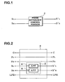
- FIG. 1 is a block diagram of an audio signal processing circuit for use in an embodiment of the present invention.
- the audio signal processing circuit includes a phase difference control portion 2.
- the phase difference control portion 2 receives a left channel signal S L for a left sound source S SL located substantially at a left side to a listener (shown in Figure 5 ) and a right channel signal S R for a right sound source S SR located substantially at a right side to the listener (also shown in Figure 5 ).
- the phase difference control portion 2 controls a phase difference between the left and right channel signals S L and S R so that the relative phase difference be from 140 degrees to 160 degrees (and preferably about 150 degrees) and outputs the phase difference controlled signals S' L and S' R for the left and right sound source, respectively.
- the signals S' L and S' R processed in the above-mentioned manner are respectively supplied to the sound sources S SL and S SR
- the circuit is capable of preventing sound image localization in the head of the listener and creating sound field just as enveloping the listener.
- the circuit is capable of performing a processing which does not compromise the sound quality (i.e., a feeling that sound image of the left and the right surround channels is comfortably localized).
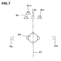
- FIG 2 is a block diagram of an audio signal processing circuit 4 which is incorporated into an audio reproduction apparatus, wherein the phase difference control portion 2 includes all pass filters (APFs) 6 and 8.
- the apparatus includes an amplifier and speakers both of which are connected to the output of the audio signal processing circuit 4 (not shown in Figure 2 ).
- a central channel signal C, a front left channel signal F L' a front right channel signal F R ' a surround left channel signal S L' a surround right channel signal S R' and a low frequency channel signal LFE are input to the circuit 4.
- the central channel signal C, the front left channel signal F L' the front right channel signal F R ' and the low frequency channel signal LFE are output without any processing.
- the surround left channel signal S L is processed with the APF 6 so as to be output as the signal S' L .
- the surround right channel signal S R is processed with the APF 8 so as to be output as the signal S' R .
- the APFs 6 and 8 constitute the phase difference control portion 2.
- FIG. 3A An example of the APF 6 is shown in Figure 3A .
- the example illustrates secondary APF.
- a frequency-phase relationship of the APF 6 is shown as a curved line 10 in Figure 4 .
- the phase of the output signal In a low frequency region, the phase of the output signal is the same as that of the input signal (i.e., the phase difference between the input and the output signals is zero).
- the phase of the output signal delays as the frequency increases, and in a high frequency region, the phase of the output signal becomes again the same as that of the input signal (i.e., the phase difference between the input and the output signals becomes 360 degrees). In other words, the phase difference between the input and the output signals varies in the range of zero to 360 degrees depending upon the frequency.
- the properties of the APF 6 represented by the curved line 10 may be adapted by selecting resistance R1 and R2 and capacitor C1 and C2.
- the APF 6 having desired properties can be designed based on the above-mentioned equations.
- FIG. 3B An example of the APF 8 is shown in Figure 3B -
- the structure thereof is basically the same as that of the APF 6.
- the properties of the APF 8. represented by a curved line 12 of Figure 4 are obtained by selecting resistance R3 and R4 and capacitor C3 and C4.
- the phase difference of 140 to 160 degrees can be obtained between the surround left channel signal S' L and the surround right channel signal S' R in a frequency region ranging from 200 Hz to 1 kHz.
- the APFs 6 and 8 control the phase difference between the signals S L and S R so that the phase of the signal S' R relatively progresses or delays 140 to 160 degrees to that of the signal S' L
- the output signals obtained in the above-mentioned manner are supplied to respective speakers as shown in Figure 5 . More specifically, the central channel signal C is supplied to a speaker S c ; the front left channel signal F L is supplied to a speaker S EL ; the front right channel signal F R is supplied to a speaker S ER ; and the low frequency channel signal LFE is supplied to a speaker S LFE. Furthermore, the surround left channel signal S' L is supplied to a speaker S SL' and the surround right channel signal S' R is supplied to a speaker S SR .
- the relative phase difference of 140 to 160 degrees can be obtained by producing a phase difference of 20 to 40 degrees between the channels with APFs and then inverting the phase of one of the channels.
- the desired phase difference is produced in the frequency region of 200 Hz to 1 kHz according to the above-mentioned embodiment, it is more preferred if the desired phase difference can be obtained in the frequency region of 50 Hz to 4 kHz.
- the higher order of the APFs widens the frequency band wherein the desired phase difference is obtained.
- the surround speakers S SL and S SR may be arranged in an angular range represented by ⁇ of Figure 5 .
- the angle range ⁇ of 60 degrees (more specifically, 30 degrees both in front and in rear with respect to the line connecting the surround speakers S SL and S SR ) is exemplified. Accordingly, in the present specification, the phrase "substantially at left and right sides to a listener" is meant to be the above-mentioned angular range ⁇ .
- Figure 6 shows a surround audio reproduction apparatus creating virtual sound sources with DSP, wherein the phase difference control portion in accordance with the present invention is incorporated.
- the respective input signals C, F L' F R' S L' S R and LFE are obtained by decoding a digitized data converted from an analog signal with an A/D converter or a digital-bit-stream encoded for surround, with a multi-channel surround decoder (not shown).
- the respective input signals are supplied to the DSP 22.
- the multi-channel surround decoder can either be incorporated into the DSP or separately provided therefrom.
- a signal for a left speaker L OUT , a signal for a right speaker R OUT and a signal for a sub-woofer speaker SUB OUT are produced by performing processings such as addition, subtraction, filtering, delay and the like with the DSP 22 to the thus-input digital data in accordance with program(s) stored in a memory 26.
- the thus-produced signals are converted into analog signals with a D/A converter 24 and are supplied to the speakers S FL' S FR and S LFE . Installation process of the program(s) into the memory 26 and other processings are carried out by a micro-processor 20.
- the speakers S FL and S FR and the virtual surround sound sources X SL and X SR are symmetrically arranged with respect to the central axis 40 through the listener as shown in Figure 7 . Since bass (sound having a low frequency) reproduced by the woofer speaker S LFR has a weak directivity and a long wavelength, the woofer speaker S LFE can be arranged at any location.
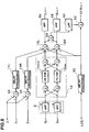
- Figure 8 is a signal-flow diagram illustrating processings carried out by the DSP 22 in accordance with the program(s) stored in the memory 26.
- the virtual central sound source X c' the virtual surround left sound source X SL and the virtual surround right sound source X SR are created by using only the front left and right speakers S FL and S FR and the low frequency speaker S LFE .
- the surround left channel signal S L and the surround right channel signal S R are subjected to a sound image localization processing with a surround sound image localization circuit 12 and are supplied to the left and the right speakers S FL and S FR arranged in front of the listener.
- the surround sound image localization circuit 12 is composed of a so-called shuffler type filter. Therefore, the effect that the surround left channel signal S L and the surround right channel signal S R are output respectively from the virtual surround left sound source X SL and the virtual surround right sound source X SR can be obtained.
- the central channel signal C is equally supplied to the left and the right speakers S FL and S FR . Therefore, the effect that the central channel signal C is output from the virtual central sound source X c can be obtained.
- Delay processing circuits 14L, 14R and 30 provide a delay time equal to that caused by the surround sound image localization circuit 12. These delay circuits can compensate the delay between the signals C, F L' F R and LFE and the signals S L and S R .
- the surround left channel signal S L and the surround right channel signal S R are subjected to a phase difference control processing with the phase difference control portion 2 in the above-mentioned manner before being supplied to the surround sound image localization circuit 12. Therefore, a relative phase difference of 140 to 160 degrees has already been produced between the surround left channel signal S L and the surround right channel signal S R .
- a secondary IIR filter as shown in Figure 9 is used as the APFs 6 and 8 constituting the phase difference control portion 2.
- the surround left channel signal S L output from the virtual surround left sound source X SL and the surround right channel signal S R output from the virtual surround right sound source X SR may be prevented from being localized in the head of the listener 50.
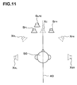
- F igu re 10 is a signal-flow diagram according to another embodiment of the present invention.
- the front left channel signal F L and the front right channel signal F R are respectively added to the surround left channel signal S L and the surround right channel signal S R which have already been subjected to the phase difference control processing.
- the front left channel signal F L is localized at the position of the virtual sound source X FL located between the positions of the left speaker S FL and the virtual surround left sound source X SL.
- the front right channel signal F R is localized at the position of the virtual sound source X FR located between the positions of the right speaker S FR and the virtual surround right sound source X SR . Accordingly, sound field created by the front left channel signal F L and the front right channel signal F R can be widened.
- an analog circuit can be used in place of the described digital circuit and a digital circuit can be used in place of the described analog circuit.
Landscapes
- Engineering & Computer Science (AREA)
- Physics & Mathematics (AREA)
- Acoustics & Sound (AREA)
- Signal Processing (AREA)
- Multimedia (AREA)
- Stereophonic System (AREA)
Claims (6)
- Appareil de reproduction audio d'ambiance ayant des canaux gauche et droit pour des sources sonores respectives (SFL, SFR) en face d'un auditeur (50), et des canaux d'ambiance gauche et droit pour des sources sonores d'ambiance respectives (SSL, SSR) sur les côtés gauche et droit par rapport à l'auditeur, ledit appareil comprenant:une partie de commande de différence de phase (2) qui reçoit un signal de canal d'ambiance gauche (SL) et un signal de canal d'ambiance droit (SR), commande une différence de phase entre les signaux des canaux d'ambiance gauche et droit afin de produire une différence de phase relative dans la gamme de 140 degrés à 160 degrés, et fournit en sortie les signaux de canaux d'ambiance gauche et droit à différence de phase commandée (S'L, S'R), respectivement destinés aux sources sonores d'ambiance gauche et droite.
- Appareil selon la revendication 1, dans lequel les sources sonores d'ambiance gauche et droite sont chacune une source sonore virtuelle (XSL, XSR) produite par un traitement de localisation d'image sonore, ledit appareil comprenant un moyen de traitement de localisation d'image sonore (12) destiné à cet effet.
- Appareil selon la revendication 1, dans lequel ladite partie de commande de différence de phase (2) produit la différence de phase relative de 140 degrés à 160 degrés dans une gamme de fréquence allant de 200 Hz à 1 kHz.
- Appareil selon la revendication 1, comprenant une source sonore d'ambiance gauche (SSL) et une source sonore d'ambiance droite (SSR) agencées symétriquement de chaque côté d'un axe central (40) passant par l'auditeur (50).
- Appareil selon la revendication 1, comprenant en outre :une partie de localisation virtuelle (12) qui reçoit un signal d'ambiance, pour fournir en sortie un signal destiné à localiser l'image sonore du signal d'ambiance à des positions situées sur le côté de l'auditeur (50) vers un haut-parleur gauche et un haut-parleur droit, etune partie à retard (14L, 14R), qui reçoit un signal de canal gauche (FL) et un signal de canal droit (FR), pour mettre en oeuvre un traitement de retard permettant d'égaliser un temps de retard du signal de canal gauche et du signal de canal droit avec un temps de retard provoqué par la partie de localisation virtuelle (12), et pour fournir en sortie respectivement les signaux retardés des canaux gauche et droit au haut-parleur gauche et au haut-parleur droit.
- Appareil selon la revendication 5, dans lequel les signaux du canal gauche et du canal droit (FL, FR) sont tous deux délivrés à la partie de localisation virtuelle (12) de façon à localiser une image sonore entre le haut-parleur gauche et le côté gauche de l'auditeur (50), et une image sonore entre le haut-parleur droit et le côté droit de l'auditeur.
Priority Applications (1)
| Application Number | Priority Date | Filing Date | Title |
|---|---|---|---|
| EP05076372A EP1571883B1 (fr) | 1998-07-31 | 1999-07-29 | Circuit de traitement du signal sonore |
Applications Claiming Priority (4)
| Application Number | Priority Date | Filing Date | Title |
|---|---|---|---|
| JP21792998A JP3368835B2 (ja) | 1998-07-31 | 1998-07-31 | 音響信号処理回路 |
| JP21821898 | 1998-07-31 | ||
| JP21821898A JP3368836B2 (ja) | 1998-07-31 | 1998-07-31 | 音響信号処理回路および方法 |
| JP21792998 | 1998-07-31 |
Related Child Applications (1)
| Application Number | Title | Priority Date | Filing Date |
|---|---|---|---|
| EP05076372A Division EP1571883B1 (fr) | 1998-07-31 | 1999-07-29 | Circuit de traitement du signal sonore |
Publications (3)
| Publication Number | Publication Date |
|---|---|
| EP0977464A2 EP0977464A2 (fr) | 2000-02-02 |
| EP0977464A3 EP0977464A3 (fr) | 2005-04-13 |
| EP0977464B1 true EP0977464B1 (fr) | 2008-09-10 |
Family
ID=26522293
Family Applications (2)
| Application Number | Title | Priority Date | Filing Date |
|---|---|---|---|
| EP05076372A Expired - Lifetime EP1571883B1 (fr) | 1998-07-31 | 1999-07-29 | Circuit de traitement du signal sonore |
| EP99306038A Expired - Lifetime EP0977464B1 (fr) | 1998-07-31 | 1999-07-29 | Circuit de traitement du signal sonore |
Family Applications Before (1)
| Application Number | Title | Priority Date | Filing Date |
|---|---|---|---|
| EP05076372A Expired - Lifetime EP1571883B1 (fr) | 1998-07-31 | 1999-07-29 | Circuit de traitement du signal sonore |
Country Status (4)
| Country | Link |
|---|---|
| US (2) | US7242782B1 (fr) |
| EP (2) | EP1571883B1 (fr) |
| CN (2) | CN100493235C (fr) |
| DE (1) | DE69939510D1 (fr) |
Families Citing this family (39)
| Publication number | Priority date | Publication date | Assignee | Title |
|---|---|---|---|---|
| JP3682032B2 (ja) * | 2002-05-13 | 2005-08-10 | 株式会社ダイマジック | オーディオ装置並びにその再生用プログラム |
| WO2004002192A1 (fr) * | 2002-06-21 | 2003-12-31 | University Of Southern California | Systeme et procede de correction acoustique automatique de salles |
| US7567675B2 (en) * | 2002-06-21 | 2009-07-28 | Audyssey Laboratories, Inc. | System and method for automatic multiple listener room acoustic correction with low filter orders |
| WO2005018134A2 (fr) | 2003-08-07 | 2005-02-24 | Quellan, Inc. | Procede et systeme pour supprimer la diaphonie |
| US8054980B2 (en) * | 2003-09-05 | 2011-11-08 | Stmicroelectronics Asia Pacific Pte, Ltd. | Apparatus and method for rendering audio information to virtualize speakers in an audio system |
| US7680289B2 (en) * | 2003-11-04 | 2010-03-16 | Texas Instruments Incorporated | Binaural sound localization using a formant-type cascade of resonators and anti-resonators |
| JP4649859B2 (ja) * | 2004-03-25 | 2011-03-16 | ソニー株式会社 | 信号処理装置および方法、記録媒体、並びにプログラム |
| KR20060003444A (ko) * | 2004-07-06 | 2006-01-11 | 삼성전자주식회사 | 모바일 기기에서 크로스토크 제거 장치 및 방법 |
| US7720237B2 (en) * | 2004-09-07 | 2010-05-18 | Audyssey Laboratories, Inc. | Phase equalization for multi-channel loudspeaker-room responses |
| US7826626B2 (en) * | 2004-09-07 | 2010-11-02 | Audyssey Laboratories, Inc. | Cross-over frequency selection and optimization of response around cross-over |
| US8077815B1 (en) * | 2004-11-16 | 2011-12-13 | Adobe Systems Incorporated | System and method for processing multi-channel digital audio signals |
| KR100608024B1 (ko) * | 2004-11-26 | 2006-08-02 | 삼성전자주식회사 | 다중 채널 오디오 입력 신호를 2채널 출력으로 재생하기위한 장치 및 방법과 이를 수행하기 위한 프로그램이기록된 기록매체 |
| WO2006057521A1 (fr) * | 2004-11-26 | 2006-06-01 | Samsung Electronics Co., Ltd. | Appareil et procede de traitement de signaux d'entree audio multicanaux pour produire a partir de ceux-ci au moins deux signaux de sortie de canaux, et support lisible par ordinateur contenant du code executable permettant la mise en oeuvre dudit procede |
| US7974418B1 (en) * | 2005-02-28 | 2011-07-05 | Texas Instruments Incorporated | Virtualizer with cross-talk cancellation and reverb |
| NL1032538C2 (nl) * | 2005-09-22 | 2008-10-02 | Samsung Electronics Co Ltd | Apparaat en werkwijze voor het reproduceren van virtueel geluid van twee kanalen. |
| KR100739776B1 (ko) * | 2005-09-22 | 2007-07-13 | 삼성전자주식회사 | 입체 음향 생성 방법 및 장치 |
| US8180067B2 (en) * | 2006-04-28 | 2012-05-15 | Harman International Industries, Incorporated | System for selectively extracting components of an audio input signal |
| US8619998B2 (en) * | 2006-08-07 | 2013-12-31 | Creative Technology Ltd | Spatial audio enhancement processing method and apparatus |
| US8036767B2 (en) | 2006-09-20 | 2011-10-11 | Harman International Industries, Incorporated | System for extracting and changing the reverberant content of an audio input signal |
| US8306245B2 (en) * | 2007-05-25 | 2012-11-06 | Marvell World Trade Ltd. | Multi-mode audio amplifiers |
| WO2009022463A1 (fr) * | 2007-08-13 | 2009-02-19 | Mitsubishi Electric Corporation | Dispositif audio |
| WO2009027886A2 (fr) * | 2007-08-28 | 2009-03-05 | Nxp B.V. | Dispositif et procédé de traitement de signaux sonores |
| JPWO2009051132A1 (ja) * | 2007-10-19 | 2011-03-03 | 日本電気株式会社 | 信号処理システムと、その装置、方法及びそのプログラム |
| US20100027799A1 (en) * | 2008-07-31 | 2010-02-04 | Sony Ericsson Mobile Communications Ab | Asymmetrical delay audio crosstalk cancellation systems, methods and electronic devices including the same |
| JP5338259B2 (ja) * | 2008-10-31 | 2013-11-13 | 富士通株式会社 | 信号処理装置、信号処理方法、および信号処理プログラム |
| KR101387195B1 (ko) * | 2009-10-05 | 2014-04-21 | 하만인터내셔날인더스트리스인코포레이티드 | 오디오 신호의 공간 추출 시스템 |
| KR20110041062A (ko) * | 2009-10-15 | 2011-04-21 | 삼성전자주식회사 | 가상 스피커 장치 및 가상 스피커 처리 방법 |
| US8380334B2 (en) * | 2010-09-07 | 2013-02-19 | Linear Acoustic, Inc. | Carrying auxiliary data within audio signals |
| US8705764B2 (en) | 2010-10-28 | 2014-04-22 | Audyssey Laboratories, Inc. | Audio content enhancement using bandwidth extension techniques |
| JP5787128B2 (ja) * | 2010-12-16 | 2015-09-30 | ソニー株式会社 | 音響システム、音響信号処理装置および方法、並びに、プログラム |
| JP5867672B2 (ja) | 2011-03-30 | 2016-02-24 | ヤマハ株式会社 | 音像定位制御装置 |
| US8964992B2 (en) | 2011-09-26 | 2015-02-24 | Paul Bruney | Psychoacoustic interface |
| JP5776597B2 (ja) * | 2012-03-23 | 2015-09-09 | ヤマハ株式会社 | 音信号処理装置 |
| CN107251578B (zh) * | 2015-02-25 | 2018-11-06 | 株式会社索思未来 | 信号处理装置 |
| CN106303821A (zh) * | 2015-06-12 | 2017-01-04 | 青岛海信电器股份有限公司 | 串音消除方法与系统 |
| US9756423B2 (en) * | 2015-09-16 | 2017-09-05 | Océ-Technologies B.V. | Method for removing electric crosstalk |
| EP3522568B1 (fr) * | 2018-01-31 | 2021-03-10 | Oticon A/s | Prothèse auditive comprenant un vibrateur touchant un pavillon |
| CN108737896B (zh) * | 2018-05-10 | 2020-11-03 | 深圳创维-Rgb电子有限公司 | 一种基于电视机的自动调节喇叭朝向的方法及电视机 |
| WO2023009377A1 (fr) * | 2021-07-28 | 2023-02-02 | Dolby Laboratories Licensing Corporation | Procédé de traitement audio pour lecture audio immersive |
Family Cites Families (26)
| Publication number | Priority date | Publication date | Assignee | Title |
|---|---|---|---|---|
| US3779288A (en) | 1972-06-14 | 1973-12-18 | Rockwell International Corp | Weft carrier guide |
| JP2536044Y2 (ja) | 1986-09-19 | 1997-05-21 | パイオニア株式会社 | 両耳相関係数補正装置 |
| US4893342A (en) * | 1987-10-15 | 1990-01-09 | Cooper Duane H | Head diffraction compensated stereo system |
| SE461308B (sv) * | 1988-06-03 | 1990-01-29 | Ericsson Telefon Ab L M | Adaptivt digitalt filter omfattande en icke rekursiv del och en rekursiv del |
| DE3932858C2 (de) | 1988-12-07 | 1996-12-19 | Onkyo Kk | Stereophonisches Wiedergabesystem |
| DE69433258T2 (de) | 1993-07-30 | 2004-07-01 | Victor Company of Japan, Ltd., Yokohama | Raumklangsignalverarbeitungsvorrichtung |
| US5761315A (en) | 1993-07-30 | 1998-06-02 | Victor Company Of Japan, Ltd. | Surround signal processing apparatus |
| JP2982627B2 (ja) | 1993-07-30 | 1999-11-29 | 日本ビクター株式会社 | サラウンド信号処理装置及び映像音声再生装置 |
| JP2642857B2 (ja) * | 1993-11-17 | 1997-08-20 | 松下電器産業株式会社 | 音響クロストーク制御装置 |
| JP3276528B2 (ja) * | 1994-08-24 | 2002-04-22 | シャープ株式会社 | 音像拡大装置 |
| JP3500746B2 (ja) | 1994-12-21 | 2004-02-23 | 松下電器産業株式会社 | 音像定位装置及びフィルタ設定方法 |
| JP2985704B2 (ja) | 1995-01-25 | 1999-12-06 | 日本ビクター株式会社 | サラウンド信号処理装置 |
| JP2953347B2 (ja) | 1995-06-06 | 1999-09-27 | 日本ビクター株式会社 | サラウンド信号処理装置 |
| JPH08265899A (ja) * | 1995-01-26 | 1996-10-11 | Victor Co Of Japan Ltd | サラウンド信号処理装置及び映像音声再生装置 |
| US5799094A (en) | 1995-01-26 | 1998-08-25 | Victor Company Of Japan, Ltd. | Surround signal processing apparatus and video and audio signal reproducing apparatus |
| US5892831A (en) * | 1995-06-30 | 1999-04-06 | Philips Electronics North America Corp. | Method and circuit for creating an expanded stereo image using phase shifting circuitry |
| JP3267118B2 (ja) | 1995-08-28 | 2002-03-18 | 日本ビクター株式会社 | 音像定位装置 |
| US5995631A (en) * | 1996-07-23 | 1999-11-30 | Kabushiki Kaisha Kawai Gakki Seisakusho | Sound image localization apparatus, stereophonic sound image enhancement apparatus, and sound image control system |
| US6052470A (en) * | 1996-09-04 | 2000-04-18 | Victor Company Of Japan, Ltd. | System for processing audio surround signal |
| TW379512B (en) * | 1997-06-30 | 2000-01-11 | Matsushita Electric Industrial Co Ltd | Apparatus for localization of a sound image |
| JP4627880B2 (ja) * | 1997-09-16 | 2011-02-09 | ドルビー ラボラトリーズ ライセンシング コーポレイション | リスナーの周囲にある音源の空間的ひろがり感を増強するためのステレオヘッドホンデバイス内でのフィルタ効果の利用 |
| US6668061B1 (en) * | 1998-11-18 | 2003-12-23 | Jonathan S. Abel | Crosstalk canceler |
| DE69924896T2 (de) * | 1998-01-23 | 2005-09-29 | Onkyo Corp., Neyagawa | Vorrichtung und Verfahren zur Schallbildlokalisierung |
| US6956954B1 (en) * | 1998-10-19 | 2005-10-18 | Onkyo Corporation | Surround-sound processing system |
| US7536017B2 (en) * | 2004-05-14 | 2009-05-19 | Texas Instruments Incorporated | Cross-talk cancellation |
| US7634092B2 (en) * | 2004-10-14 | 2009-12-15 | Dolby Laboratories Licensing Corporation | Head related transfer functions for panned stereo audio content |
-
1999
- 1999-07-28 US US09/361,734 patent/US7242782B1/en not_active Expired - Fee Related
- 1999-07-29 DE DE69939510T patent/DE69939510D1/de not_active Expired - Lifetime
- 1999-07-29 EP EP05076372A patent/EP1571883B1/fr not_active Expired - Lifetime
- 1999-07-29 EP EP99306038A patent/EP0977464B1/fr not_active Expired - Lifetime
- 1999-07-30 CN CNB2003101028538A patent/CN100493235C/zh not_active Expired - Lifetime
- 1999-07-30 CN CNB991118618A patent/CN1148995C/zh not_active Expired - Lifetime
-
2005
- 2005-06-02 US US11/142,229 patent/US7801312B2/en not_active Expired - Fee Related
Also Published As
| Publication number | Publication date |
|---|---|
| CN100493235C (zh) | 2009-05-27 |
| CN1516520A (zh) | 2004-07-28 |
| DE69939510D1 (de) | 2008-10-23 |
| US20050220312A1 (en) | 2005-10-06 |
| EP1571883A1 (fr) | 2005-09-07 |
| US7242782B1 (en) | 2007-07-10 |
| CN1250346A (zh) | 2000-04-12 |
| EP0977464A3 (fr) | 2005-04-13 |
| EP1571883B1 (fr) | 2012-05-30 |
| EP0977464A2 (fr) | 2000-02-02 |
| CN1148995C (zh) | 2004-05-05 |
| US7801312B2 (en) | 2010-09-21 |
Similar Documents
| Publication | Publication Date | Title |
|---|---|---|
| EP0977464B1 (fr) | Circuit de traitement du signal sonore | |
| US7369666B2 (en) | Audio reproducing system | |
| JP4866354B2 (ja) | 相関出力を使用したオーディオ・チャネル混合方法 | |
| US5710818A (en) | Apparatus for expanding and controlling sound fields | |
| KR100644617B1 (ko) | 7.1 채널 오디오 재생 방법 및 장치 | |
| JP2708105B2 (ja) | 車載用音響再生装置 | |
| JP4350905B2 (ja) | サラウンド処理システム | |
| US20070133831A1 (en) | Apparatus and method of reproducing virtual sound of two channels | |
| US20060274900A1 (en) | 5-2-5 matrix encoder and decoder system | |
| US6504933B1 (en) | Three-dimensional sound system and method using head related transfer function | |
| US5590204A (en) | Device for reproducing 2-channel sound field and method therefor | |
| US20080037794A1 (en) | Acoustic System | |
| EP0917400B1 (fr) | Appareil et méthode pour la localisation de l'image sonore | |
| US5844993A (en) | Surround signal processing apparatus | |
| EP2134108B1 (fr) | Dispositif de traitement sonore, appareil de haut-parleur et procédé de traitement sonore | |
| JPH0965500A (ja) | 音場制御装置 | |
| JP3368835B2 (ja) | 音響信号処理回路 | |
| JP2985704B2 (ja) | サラウンド信号処理装置 | |
| JP4943098B2 (ja) | 音響再生システム及び音響再生方法 | |
| JP3106788B2 (ja) | 車載用音場補正装置 | |
| KR100279710B1 (ko) | 실조화음향공간구현장치 | |
| JP2008154082A (ja) | 音場再生装置 | |
| US20030142830A1 (en) | Audio center channel phantomizer | |
| JPH0834653B2 (ja) | 音場拡大制御装置 | |
| JPH01223895A (ja) | 音響再生装置 |
Legal Events
| Date | Code | Title | Description |
|---|---|---|---|
| PUAI | Public reference made under article 153(3) epc to a published international application that has entered the european phase |
Free format text: ORIGINAL CODE: 0009012 |
|
| AK | Designated contracting states |
Kind code of ref document: A2 Designated state(s): AT BE CH CY DE DK ES FI FR GB GR IE IT LI LU MC NL PT SE |
|
| AX | Request for extension of the european patent |
Free format text: AL;LT;LV;MK;RO;SI |
|
| PUAL | Search report despatched |
Free format text: ORIGINAL CODE: 0009013 |
|
| AK | Designated contracting states |
Kind code of ref document: A3 Designated state(s): AT BE CH CY DE DK ES FI FR GB GR IE IT LI LU MC NL PT SE |
|
| AX | Request for extension of the european patent |
Extension state: AL LT LV MK RO SI |
|
| 17P | Request for examination filed |
Effective date: 20050825 |
|
| AKX | Designation fees paid |
Designated state(s): DE GB |
|
| GRAP | Despatch of communication of intention to grant a patent |
Free format text: ORIGINAL CODE: EPIDOSNIGR1 |
|
| GRAS | Grant fee paid |
Free format text: ORIGINAL CODE: EPIDOSNIGR3 |
|
| GRAA | (expected) grant |
Free format text: ORIGINAL CODE: 0009210 |
|
| AK | Designated contracting states |
Kind code of ref document: B1 Designated state(s): DE GB |
|
| REG | Reference to a national code |
Ref country code: GB Ref legal event code: FG4D |
|
| REF | Corresponds to: |
Ref document number: 69939510 Country of ref document: DE Date of ref document: 20081023 Kind code of ref document: P |
|
| PLBE | No opposition filed within time limit |
Free format text: ORIGINAL CODE: 0009261 |
|
| STAA | Information on the status of an ep patent application or granted ep patent |
Free format text: STATUS: NO OPPOSITION FILED WITHIN TIME LIMIT |
|
| 26N | No opposition filed |
Effective date: 20090611 |
|
| REG | Reference to a national code |
Ref country code: DE Ref legal event code: R081 Ref document number: 69939510 Country of ref document: DE Owner name: ONKYO CORP., NEYAGAWA-SHI, JP Free format text: FORMER OWNER: ONKYO CORP., NEYAGAWA, OSAKA, JP Effective date: 20110302 |
|
| REG | Reference to a national code |
Ref country code: DE Ref legal event code: R082 Ref document number: 69939510 Country of ref document: DE |
|
| PGFP | Annual fee paid to national office [announced via postgrant information from national office to epo] |
Ref country code: DE Payment date: 20180717 Year of fee payment: 20 |
|
| PGFP | Annual fee paid to national office [announced via postgrant information from national office to epo] |
Ref country code: GB Payment date: 20180725 Year of fee payment: 20 |
|
| REG | Reference to a national code |
Ref country code: DE Ref legal event code: R071 Ref document number: 69939510 Country of ref document: DE |
|
| REG | Reference to a national code |
Ref country code: GB Ref legal event code: PE20 Expiry date: 20190728 |
|
| PG25 | Lapsed in a contracting state [announced via postgrant information from national office to epo] |
Ref country code: GB Free format text: LAPSE BECAUSE OF EXPIRATION OF PROTECTION Effective date: 20190728 |