EP0979668A2 - Décharge pour des eaux usées - Google Patents
Décharge pour des eaux usées Download PDFInfo
- Publication number
- EP0979668A2 EP0979668A2 EP99114868A EP99114868A EP0979668A2 EP 0979668 A2 EP0979668 A2 EP 0979668A2 EP 99114868 A EP99114868 A EP 99114868A EP 99114868 A EP99114868 A EP 99114868A EP 0979668 A2 EP0979668 A2 EP 0979668A2
- Authority
- EP
- European Patent Office
- Prior art keywords
- clear water
- drain
- trigger
- inlet area
- weir
- Prior art date
- Legal status (The legal status is an assumption and is not a legal conclusion. Google has not performed a legal analysis and makes no representation as to the accuracy of the status listed.)
- Granted
Links
Images


Classifications
-
- B—PERFORMING OPERATIONS; TRANSPORTING
- B01—PHYSICAL OR CHEMICAL PROCESSES OR APPARATUS IN GENERAL
- B01D—SEPARATION
- B01D17/00—Separation of liquids, not provided for elsewhere, e.g. by thermal diffusion
-
- B—PERFORMING OPERATIONS; TRANSPORTING
- B01—PHYSICAL OR CHEMICAL PROCESSES OR APPARATUS IN GENERAL
- B01D—SEPARATION
- B01D17/00—Separation of liquids, not provided for elsewhere, e.g. by thermal diffusion
- B01D17/02—Separation of non-miscible liquids
- B01D17/0208—Separation of non-miscible liquids by sedimentation
- B01D17/0214—Separation of non-miscible liquids by sedimentation with removal of one of the phases
-
- B—PERFORMING OPERATIONS; TRANSPORTING
- B01—PHYSICAL OR CHEMICAL PROCESSES OR APPARATUS IN GENERAL
- B01D—SEPARATION
- B01D21/00—Separation of suspended solid particles from liquids by sedimentation
- B01D21/24—Feed or discharge mechanisms for settling tanks
- B01D21/2444—Discharge mechanisms for the classified liquid
-
- B—PERFORMING OPERATIONS; TRANSPORTING
- B01—PHYSICAL OR CHEMICAL PROCESSES OR APPARATUS IN GENERAL
- B01D—SEPARATION
- B01D21/00—Separation of suspended solid particles from liquids by sedimentation
- B01D21/24—Feed or discharge mechanisms for settling tanks
- B01D21/2494—Feed or discharge mechanisms for settling tanks provided with means for the removal of gas, e.g. noxious gas, air
Definitions
- the present invention relates to a clear water drain, in particular for drainage of clear water from SBR plants, with a float, one arranged on it lockable trigger element, which has an inlet area for feeding the Has clear water in the fume cupboard, as well as with one with the fume cupboard connected drain pipe for the discharge of the clear water.
- Clear water fume cupboards of this type are widely used and used in SBR systems here, at the end of the biological treatment of wastewater, i.e. at the end of an SBR cycle to drain the water treated during each cycle or to decant.
- the clear water drain must fulfill the tasks on the one hand to ensure the discharge of the treated water, on the other hand however, retain the biomass in the reactor so that it can be used for further treatment cycles is available.
- the biomass lies during the clear water withdrawal for the most part sedimented and for a small part on the water surface floating, i.e. floats, before.
- an optimal clear water drain that this is arranged in a floating manner to keep the greatest possible distance to the to ensure sedimented sludge.
- a clear water drain be designed to be lockable. This makes it possible to deduct only open when clear water is to be drained while it is in the rest Times, i.e. is completely closed during the ventilation and mixing phases. This ensures that no sludge can penetrate the clear water drain also gets into the drain.
- an ideal clear water drain must also fulfill the task of water not directly on the surface of the water, but subtracted below to suit hold back from the floating mud. Furthermore, the clear water drain be designed so that the flow velocities at the end of the water are limited so that sedimented sludge is not carried away.
- This task is based on a generic clear water drain solved in that the inlet area is designed such that this by means of a Air or gas cushion is closable that means are provided by means of of which the air or gas cushion can be generated in the inlet area, and that a Ventilation device is provided, by means of which the air or gas cushion is deductible from the inlet area.
- a clear water drain designed in this way is fulfilled the above requirements and also has the advantage that to close the clear water drain or the trigger element no mechanical moving parts are required. Rather, the closing is based on the Creation of an air or gas cushion, which is located in the inlet area of the exhaust element is arranged that it can be closed reliably and accordingly prevents water from entering the fume cupboard.
- the inlet area arranged between the trigger element and the floating body.
- the trigger element is designed as a trigger weir is.
- the inlet area of the clear water drainage can through the overflow edge of the Trigger weir and a groove-shaped recess opposite one of the trigger weir arranged component of the clear water drain are formed.
- an air or Gas cushion formed in the groove-shaped recess, which allows access to Water over the overflow edge of the trigger weir is effectively prevented.
- this is the Trigger weir located opposite component of the float of the clear water drain.
- any other component to provide a corresponding one on its side assigned to the overflow edge has groove-shaped recess.
- the ventilation device includes a valve.
- the means of generating an air or Gas cushions can include a compressor.
- the guide elements are arranged in the sense of a parallelogram, which ensures that the horizontal orientation of the trigger element and the float regardless of the height of the water level is maintained.
- At least one of the guide elements on the clear water drain and on the fastening device is articulated at two points each.
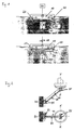
- Fig. 1 shows a schematic cross-sectional view of the invention Clear water drainage when closed (top) and during the decanting phase (below).
- the trigger weir 30 is arranged which the has circumferential overflow edge 32.
- the floating body 10 has in its lower, the groove-shaped area arranged opposite the overflow edge 32 Recess 12 on the inlet area 20 of the trigger weir 30 becomes corresponding limited by the overflow edge 32 and the groove-shaped recess 12.
- a compressor 50 is also provided, which is connected to the flexible line Float 10 is connected, wherein within the float 10 Lines for supplying the compressed air to the groove-shaped recess 12 are provided are.
- the trigger weir 30 is connected in its lower region to the drain line 40, through which the clear water supplied to the trigger weir 30 is removed therefrom becomes.
- a valve 60 is also provided, which can be used with the in the floating body 10 extending air or gas lines leading to the groove-shaped Run version 12, communicating.
- Fig. 1 above is the valve 60 and in Fig. 1, the compressor 50 not shown below.
- the trigger weir 30 If the trigger weir 30 is to be closed, the compressor 50 and the lines of compressed air or any gas mixture extending from it led into the groove-shaped recesses 12, whereby a corresponding Air or gas cushion is created.
- the overflow edge 32 of the trigger weir 30 arranged according to the invention such that an overflow over this Edge 32 becomes impossible due to clear water if the groove-shaped recess 12 is filled with the air or gas mixture.
- the drain line 40 also has a (not shown) and preferably outside of the clear water basin arranged shut-off valve that only opens when clear water is to be drained.
- valve shown in Fig. 1, below 60 opened, whereby the air or gas from the groove-shaped recess 12th is discharged and the inlet area 20 is released for the passage of water becomes.
- the water initially flows according to the arrows shown in Fig. 1, below through the inlet area 20 into the trigger weir 30 and is from this discharged through the drain line 40.
- top shows a schematic side view of the clear water drain and arranged on the fastening device 70 and running in parallel Guide elements 40, 80.
- the guide element 40 is through the drain line 40 formed.
- Both guide elements 40, 80 are by means of the pivot axes 85 swiveling with the clear water drain as well as with the fastening device 70 connected.
- the distance of the pivot axes 85 on the fastening device 70 and the clear water drain is identical.
- the swivel axes 85 thus define the four corner points of a parallelogram.
- Fig. 2 shows that the guide element 80 on the clear water drain as well is articulated on the fastening device 70 at two points 85 in each case. Out of it it follows that a possibility of moving the clear water drain in the Level X-X no longer exists.
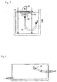
- Fig. 3 shows a generic clear water drain with float 10 and trigger weir 30 arranged below it mechanically operated valve opened and closed, the valve actuation due to the mechanism 90 located above the floating body 10 is effected.
- the trigger weir 30 is for discharging the clear water with the drain pipe 40 connected.
- Fig. 4 shows a decanting device in which the clear water drain is always below the water surface. This has the disadvantage that during the Venting and mixing closing the drain line 40 is impossible, which is causes mud to enter drain line 40 during these times.
- Fig. 5 shows a clear water drain, in which a drain pan 100 by means of a mechanical lowering device 110 can be lowered into the basin while the tub 100 is lifted out of the pool during the remaining times.
- a clear water drain is a disadvantage that the drain pan 100 is always driven through the floating sludge layer when lowering and always picks up swimming mud when lifting and removes it from the pool.
- Fig. 7 finally shows a clear water drain, in which the clear water over a Trigger weir 30 is deducted, which is attached to floating bodies 10 and accordingly in this way is always kept on the water surface.
- the drain line 40 is telescopic and is at Lowering the water level by a corresponding amount.
- This has the disadvantage that the seal of the telescopic together connected drain lines 40 is poorly executable, causing sludge can penetrate into the drain line 40.
Landscapes
- Chemical & Material Sciences (AREA)
- Chemical Kinetics & Catalysis (AREA)
- Physics & Mathematics (AREA)
- Thermal Sciences (AREA)
- Health & Medical Sciences (AREA)
- Toxicology (AREA)
- Float Valves (AREA)
- Farming Of Fish And Shellfish (AREA)
- Sink And Installation For Waste Water (AREA)
- Electrical Discharge Machining, Electrochemical Machining, And Combined Machining (AREA)
- Physical Water Treatments (AREA)
- Removal Of Floating Material (AREA)
- Cleaning Or Clearing Of The Surface Of Open Water (AREA)
- Treatment Of Water By Oxidation Or Reduction (AREA)
- Nozzles (AREA)
- Water Treatment By Sorption (AREA)
Applications Claiming Priority (2)
| Application Number | Priority Date | Filing Date | Title |
|---|---|---|---|
| DE19836563 | 1998-08-12 | ||
| DE19836563A DE19836563A1 (de) | 1998-08-12 | 1998-08-12 | Klarwasserabzug |
Publications (3)
| Publication Number | Publication Date |
|---|---|
| EP0979668A2 true EP0979668A2 (fr) | 2000-02-16 |
| EP0979668A3 EP0979668A3 (fr) | 2001-10-31 |
| EP0979668B1 EP0979668B1 (fr) | 2006-11-29 |
Family
ID=7877315
Family Applications (1)
| Application Number | Title | Priority Date | Filing Date |
|---|---|---|---|
| EP99114868A Expired - Lifetime EP0979668B1 (fr) | 1998-08-12 | 1999-07-29 | Décharge pour des eaux clarifiées |
Country Status (7)
| Country | Link |
|---|---|
| EP (1) | EP0979668B1 (fr) |
| AT (1) | ATE346667T1 (fr) |
| CA (1) | CA2280216C (fr) |
| DE (2) | DE19836563A1 (fr) |
| DK (1) | DK0979668T3 (fr) |
| ES (1) | ES2275324T3 (fr) |
| PT (1) | PT979668E (fr) |
Cited By (5)
| Publication number | Priority date | Publication date | Assignee | Title |
|---|---|---|---|---|
| EP1192978A3 (fr) * | 2000-10-02 | 2003-01-29 | Passavant -Roediger Anlagenbau GmbH | Dispositif et procédé de soutirage de liquide d'un récipient tel qu'un bassin |
| EP1652821A1 (fr) * | 2004-10-30 | 2006-05-03 | Ferrus Cyklar GmbH | Dispositif d'extraction d'eau claire |
| WO2008014856A1 (fr) * | 2006-08-04 | 2008-02-07 | Invent Umwelt- Und Verfahrenstechnik Ag | Décanteur doté d'un tube d'évacuation pivotant |
| WO2013160030A1 (fr) * | 2012-04-27 | 2013-10-31 | Invent Umwelt- Und Verfahrenstechnik Ag | Dispositif pour décanter un excès prélevé dans un bassin de décantation |
| WO2016168880A1 (fr) | 2015-04-23 | 2016-10-27 | Bernhard Wett | Procédé servant à évacuer l'eau d'un bassin |
Families Citing this family (4)
| Publication number | Priority date | Publication date | Assignee | Title |
|---|---|---|---|---|
| DE20001523U1 (de) * | 2000-01-24 | 2000-06-15 | Dederichs, Axel, Dipl.-Ing., 23911 Schmilau | Klarwasserabzugseinrichtung |
| DE20218583U1 (de) | 2002-11-29 | 2003-03-13 | Sotralentz Packaging S.A.S., Drulingen | Beschickvorrichtung für Flüssigkeiten, insbesondere Abwässer |
| DE102009017146A1 (de) | 2009-04-15 | 2010-10-28 | Flexitex Gmbh Kunnersdorf | Trennverfahren für Dispersionen |
| DE102009042292B3 (de) * | 2009-09-19 | 2011-01-27 | BIONIK GmbH - Innovative Technik für die Umwelt | Vorrichtung und Verfahren zum Abzug von Klarwasser aus einem Klärbecken |
Family Cites Families (7)
| Publication number | Priority date | Publication date | Assignee | Title |
|---|---|---|---|---|
| US4695376A (en) * | 1986-10-20 | 1987-09-22 | Aqua-Aerobic Systems, Inc. | Floating decanter |
| DE3718670A1 (de) * | 1987-06-04 | 1988-12-22 | Norddeutsche Affinerie | Vorrichtung zur entnahme von geklaertem wasser aus insbesondere absetzbecken |
| US5118412A (en) * | 1991-04-17 | 1992-06-02 | Schmidt Richard J | Fluid recovery apparatus |
| US5154835A (en) * | 1991-12-10 | 1992-10-13 | Environmental Systems & Services, Inc. | Collection and separation of liquids of different densities utilizing fluid pressure level control |
| DE4215596A1 (de) * | 1992-05-12 | 1993-11-18 | Stamag Stahl Und Maschinenbau | Ab- und Überlaufvorrichtung für Flüssigkeiten |
| DE19636153A1 (de) * | 1996-09-06 | 1998-03-12 | Schreiber Berthold | Einrichtung zum Abziehen der Klarwasserschicht in einer Kläranlage zur biologischen Abwasserbehandlung |
| DE29722637U1 (de) * | 1997-12-22 | 1998-05-20 | Roediger Anlagenbau-GmbH, 63450 Hanau | Anordnung zum Abziehen von Klarwasser |
-
1998
- 1998-08-12 DE DE19836563A patent/DE19836563A1/de not_active Ceased
-
1999
- 1999-07-29 EP EP99114868A patent/EP0979668B1/fr not_active Expired - Lifetime
- 1999-07-29 DE DE59914019T patent/DE59914019D1/de not_active Expired - Lifetime
- 1999-07-29 AT AT99114868T patent/ATE346667T1/de active
- 1999-07-29 ES ES99114868T patent/ES2275324T3/es not_active Expired - Lifetime
- 1999-07-29 PT PT99114868T patent/PT979668E/pt unknown
- 1999-07-29 DK DK99114868T patent/DK0979668T3/da active
- 1999-08-10 CA CA002280216A patent/CA2280216C/fr not_active Expired - Lifetime
Cited By (10)
| Publication number | Priority date | Publication date | Assignee | Title |
|---|---|---|---|---|
| EP1192978A3 (fr) * | 2000-10-02 | 2003-01-29 | Passavant -Roediger Anlagenbau GmbH | Dispositif et procédé de soutirage de liquide d'un récipient tel qu'un bassin |
| EP1652821A1 (fr) * | 2004-10-30 | 2006-05-03 | Ferrus Cyklar GmbH | Dispositif d'extraction d'eau claire |
| WO2008014856A1 (fr) * | 2006-08-04 | 2008-02-07 | Invent Umwelt- Und Verfahrenstechnik Ag | Décanteur doté d'un tube d'évacuation pivotant |
| US7871516B2 (en) | 2006-08-04 | 2011-01-18 | Invent Umwelt-Und Verfahrenstechnik Ag | Decanter with swivel discharge pipe |
| WO2013160030A1 (fr) * | 2012-04-27 | 2013-10-31 | Invent Umwelt- Und Verfahrenstechnik Ag | Dispositif pour décanter un excès prélevé dans un bassin de décantation |
| CN104302373A (zh) * | 2012-04-27 | 2015-01-21 | 英文特环境及工艺股份公司 | 用于对容纳在澄清器中的上层清液进行滗析的装置 |
| CN104302373B (zh) * | 2012-04-27 | 2015-12-09 | 英文特环境及工艺股份公司 | 用于对容纳在澄清器中的上层清液进行滗析的装置 |
| US9586161B2 (en) | 2012-04-27 | 2017-03-07 | Invent Umwelt—Und Verfahrenstechnik Ag | Device for decanting a supernatant received in a clarifier |
| WO2016168880A1 (fr) | 2015-04-23 | 2016-10-27 | Bernhard Wett | Procédé servant à évacuer l'eau d'un bassin |
| AT517129B1 (de) * | 2015-04-23 | 2017-09-15 | Bernhard Wett Dr | Verfahren zum abzug von wasser aus einem becken |
Also Published As
| Publication number | Publication date |
|---|---|
| EP0979668B1 (fr) | 2006-11-29 |
| CA2280216A1 (fr) | 2000-02-12 |
| ATE346667T1 (de) | 2006-12-15 |
| CA2280216C (fr) | 2008-11-04 |
| DE59914019D1 (de) | 2007-01-11 |
| PT979668E (pt) | 2007-01-31 |
| EP0979668A3 (fr) | 2001-10-31 |
| DK0979668T3 (da) | 2007-02-19 |
| ES2275324T3 (es) | 2007-06-01 |
| DE19836563A1 (de) | 2000-02-24 |
Similar Documents
| Publication | Publication Date | Title |
|---|---|---|
| DE202009010367U1 (de) | Vorrichtung zur Trennung von Regenwasser von chemisch, biologisch und/oder toxisch belasteten Abwässern | |
| DE202012100958U1 (de) | Biologische Klärvorrichtung | |
| DE69904574T2 (de) | Vorrichtung zur rückgewinnung der schwimmstoffe in klärbecken | |
| EP0979668B1 (fr) | Décharge pour des eaux clarifiées | |
| DE1461395A1 (de) | Steuereinrichtung fuer die Fluessigkeitsstroeme in einer Filteranlage | |
| EP1137467B1 (fr) | Dispositif d'extraction d'eau claire a partir d'installations a decantation a fonctionnement discontinu | |
| DE2710256C2 (de) | Abscheidevorrichtung mit Sinkstoffabscheider, Leichtstoffabscheider und Pumpe | |
| DE19636153A1 (de) | Einrichtung zum Abziehen der Klarwasserschicht in einer Kläranlage zur biologischen Abwasserbehandlung | |
| DE10053730B4 (de) | Klarwasserabzugseinrichtung | |
| EP2840193A1 (fr) | Bouche d'égout et son insert | |
| DE102009042292B3 (de) | Vorrichtung und Verfahren zum Abzug von Klarwasser aus einem Klärbecken | |
| EP1138363B1 (fr) | Dispositif de soutirage d'eau purifiée d'un récipient lors de la purification biologique d'eaux usées | |
| EP0565483B1 (fr) | Bassin dans une installation d'eaux usées | |
| EP1775395A1 (fr) | Dispositif d'écoulement pour installations sanitaires | |
| DE2845677A1 (de) | Vorrichtung zur waermerueckgewinnung aus abwaessern | |
| DE4140992C2 (de) | Zwei-Kammer-Abscheidevorrichtung | |
| EP4110497B1 (fr) | Dispositif de soutirage d'eau clarifiée (décanteur) pour installation de clarification | |
| DE2444241A1 (de) | Verfahren und vorrichtung zum abtrennen der anorganischen feststoffe von den organischen aus abwasserschlamm | |
| EP0535197B1 (fr) | Dispositif pour separer la boue biologique de l'eau epuree | |
| EP4520887B1 (fr) | Bouche d'égout avec piège à odeurs | |
| DE102019122938A1 (de) | Klärüberlauf und Durchlaufbecken | |
| DE4330838C2 (de) | Pumpstation für Flüssigkeiten | |
| DE69211289T2 (de) | Fettabscheider | |
| DE29710398U1 (de) | Vorrichtung zum Abziehen von gereinigtem Wasser aus einem Behälter bei der biologischen Reinigung von Abwasser | |
| DE20108021U1 (de) | Vorrichtung zur Installation im Bereich der an einen Überlaufkanal anschließbaren Überlauföffnung einer Badewanne o.dgl. Aufnahmebehälter |
Legal Events
| Date | Code | Title | Description |
|---|---|---|---|
| PUAI | Public reference made under article 153(3) epc to a published international application that has entered the european phase |
Free format text: ORIGINAL CODE: 0009012 |
|
| AK | Designated contracting states |
Kind code of ref document: A2 Designated state(s): AT BE CH CY DE DK ES FI FR GB GR IE IT LI LU MC NL PT SE |
|
| AX | Request for extension of the european patent |
Free format text: AL;LT;LV;MK;RO;SI |
|
| PUAL | Search report despatched |
Free format text: ORIGINAL CODE: 0009013 |
|
| AK | Designated contracting states |
Kind code of ref document: A3 Designated state(s): AT BE CH CY DE DK ES FI FR GB GR IE IT LI LU MC NL PT SE |
|
| AX | Request for extension of the european patent |
Free format text: AL;LT;LV;MK;RO;SI |
|
| 17P | Request for examination filed |
Effective date: 20020423 |
|
| AKX | Designation fees paid |
Free format text: AT BE CH CY DE DK ES FI FR GB GR IE IT LI LU MC NL PT SE |
|
| GRAP | Despatch of communication of intention to grant a patent |
Free format text: ORIGINAL CODE: EPIDOSNIGR1 |
|
| RTI1 | Title (correction) |
Free format text: DISCHARGE FOR CLARIFIED WATER |
|
| RAP1 | Party data changed (applicant data changed or rights of an application transferred) |
Owner name: DEGREMONT |
|
| GRAS | Grant fee paid |
Free format text: ORIGINAL CODE: EPIDOSNIGR3 |
|
| GRAA | (expected) grant |
Free format text: ORIGINAL CODE: 0009210 |
|
| AK | Designated contracting states |
Kind code of ref document: B1 Designated state(s): AT BE CH CY DE DK ES FI FR GB GR IE IT LI LU MC NL PT SE |
|
| REG | Reference to a national code |
Ref country code: GB Ref legal event code: FG4D Free format text: NOT ENGLISH |
|
| REG | Reference to a national code |
Ref country code: SE Ref legal event code: TRGR |
|
| REG | Reference to a national code |
Ref country code: CH Ref legal event code: NV Representative=s name: BOVARD AG PATENTANWAELTE Ref country code: IE Ref legal event code: FG4D Free format text: LANGUAGE OF EP DOCUMENT: GERMAN Ref country code: CH Ref legal event code: EP |
|
| REG | Reference to a national code |
Ref country code: IE Ref legal event code: FG4D Free format text: LANGUAGE OF EP DOCUMENT: GERMAN |
|
| REF | Corresponds to: |
Ref document number: 59914019 Country of ref document: DE Date of ref document: 20070111 Kind code of ref document: P |
|
| REG | Reference to a national code |
Ref country code: PT Ref legal event code: SC4A Free format text: AVAILABILITY OF NATIONAL TRANSLATION Effective date: 20061207 |
|
| GBT | Gb: translation of ep patent filed (gb section 77(6)(a)/1977) |
Effective date: 20070207 |
|
| REG | Reference to a national code |
Ref country code: GR Ref legal event code: EP Ref document number: 20070400562 Country of ref document: GR |
|
| ET | Fr: translation filed | ||
| REG | Reference to a national code |
Ref country code: ES Ref legal event code: FG2A Ref document number: 2275324 Country of ref document: ES Kind code of ref document: T3 |
|
| PLBE | No opposition filed within time limit |
Free format text: ORIGINAL CODE: 0009261 |
|
| STAA | Information on the status of an ep patent application or granted ep patent |
Free format text: STATUS: NO OPPOSITION FILED WITHIN TIME LIMIT |
|
| 26N | No opposition filed |
Effective date: 20070830 |
|
| PG25 | Lapsed in a contracting state [announced via postgrant information from national office to epo] |
Ref country code: MC Free format text: LAPSE BECAUSE OF NON-PAYMENT OF DUE FEES Effective date: 20070731 |
|
| PG25 | Lapsed in a contracting state [announced via postgrant information from national office to epo] |
Ref country code: CY Free format text: LAPSE BECAUSE OF NON-PAYMENT OF DUE FEES Effective date: 20070729 |
|
| PG25 | Lapsed in a contracting state [announced via postgrant information from national office to epo] |
Ref country code: LU Free format text: LAPSE BECAUSE OF NON-PAYMENT OF DUE FEES Effective date: 20070729 |
|
| REG | Reference to a national code |
Ref country code: CH Ref legal event code: PFA Owner name: DEGREMONT Free format text: DEGREMONT#183, AVENUE DU 18 JUIN 1940#92500 RUEIL-MALMAISON (FR) -TRANSFER TO- DEGREMONT#183, AVENUE DU 18 JUIN 1940#92500 RUEIL-MALMAISON (FR) |
|
| PGFP | Annual fee paid to national office [announced via postgrant information from national office to epo] |
Ref country code: IE Payment date: 20110709 Year of fee payment: 13 Ref country code: DK Payment date: 20110721 Year of fee payment: 13 |
|
| PGFP | Annual fee paid to national office [announced via postgrant information from national office to epo] |
Ref country code: GB Payment date: 20110721 Year of fee payment: 13 Ref country code: GR Payment date: 20110728 Year of fee payment: 13 Ref country code: SE Payment date: 20110712 Year of fee payment: 13 Ref country code: FI Payment date: 20110715 Year of fee payment: 13 |
|
| REG | Reference to a national code |
Ref country code: GR Ref legal event code: ML Ref document number: 20070400562 Country of ref document: GR Effective date: 20130104 |
|
| REG | Reference to a national code |
Ref country code: SE Ref legal event code: EUG |
|
| GBPC | Gb: european patent ceased through non-payment of renewal fee |
Effective date: 20120729 |
|
| PG25 | Lapsed in a contracting state [announced via postgrant information from national office to epo] |
Ref country code: SE Free format text: LAPSE BECAUSE OF NON-PAYMENT OF DUE FEES Effective date: 20120730 Ref country code: FI Free format text: LAPSE BECAUSE OF NON-PAYMENT OF DUE FEES Effective date: 20120729 Ref country code: GB Free format text: LAPSE BECAUSE OF NON-PAYMENT OF DUE FEES Effective date: 20120729 |
|
| REG | Reference to a national code |
Ref country code: IE Ref legal event code: MM4A |
|
| PG25 | Lapsed in a contracting state [announced via postgrant information from national office to epo] |
Ref country code: GR Free format text: LAPSE BECAUSE OF NON-PAYMENT OF DUE FEES Effective date: 20130204 |
|
| PG25 | Lapsed in a contracting state [announced via postgrant information from national office to epo] |
Ref country code: IE Free format text: LAPSE BECAUSE OF NON-PAYMENT OF DUE FEES Effective date: 20120729 |
|
| REG | Reference to a national code |
Ref country code: DK Ref legal event code: EBP Effective date: 20130731 |
|
| PG25 | Lapsed in a contracting state [announced via postgrant information from national office to epo] |
Ref country code: DK Free format text: LAPSE BECAUSE OF NON-PAYMENT OF DUE FEES Effective date: 20130731 |
|
| REG | Reference to a national code |
Ref country code: DE Ref legal event code: R082 Ref document number: 59914019 Country of ref document: DE Representative=s name: FLEUCHAUS & GALLO PARTNERSCHAFT MBB, DE |
|
| REG | Reference to a national code |
Ref country code: FR Ref legal event code: PLFP Year of fee payment: 17 |
|
| PGFP | Annual fee paid to national office [announced via postgrant information from national office to epo] |
Ref country code: AT Payment date: 20150727 Year of fee payment: 17 |
|
| REG | Reference to a national code |
Ref country code: FR Ref legal event code: PLFP Year of fee payment: 18 |
|
| PG25 | Lapsed in a contracting state [announced via postgrant information from national office to epo] |
Ref country code: BE Free format text: LAPSE BECAUSE OF NON-PAYMENT OF DUE FEES Effective date: 20160731 |
|
| PG25 | Lapsed in a contracting state [announced via postgrant information from national office to epo] |
Ref country code: BE Free format text: LAPSE BECAUSE OF NON-PAYMENT OF DUE FEES Effective date: 20160731 |
|
| PGRI | Patent reinstated in contracting state [announced from national office to epo] |
Ref country code: BE Effective date: 20161214 |
|
| REG | Reference to a national code |
Ref country code: AT Ref legal event code: MM01 Ref document number: 346667 Country of ref document: AT Kind code of ref document: T Effective date: 20160729 |
|
| PG25 | Lapsed in a contracting state [announced via postgrant information from national office to epo] |
Ref country code: AT Free format text: LAPSE BECAUSE OF NON-PAYMENT OF DUE FEES Effective date: 20160729 |
|
| REG | Reference to a national code |
Ref country code: FR Ref legal event code: PLFP Year of fee payment: 19 |
|
| REG | Reference to a national code |
Ref country code: FR Ref legal event code: PLFP Year of fee payment: 20 |
|
| PGFP | Annual fee paid to national office [announced via postgrant information from national office to epo] |
Ref country code: PT Payment date: 20180621 Year of fee payment: 20 |
|
| PGFP | Annual fee paid to national office [announced via postgrant information from national office to epo] |
Ref country code: FR Payment date: 20180622 Year of fee payment: 20 Ref country code: BE Payment date: 20180621 Year of fee payment: 20 Ref country code: IT Payment date: 20180525 Year of fee payment: 20 |
|
| PGFP | Annual fee paid to national office [announced via postgrant information from national office to epo] |
Ref country code: NL Payment date: 20180724 Year of fee payment: 20 Ref country code: ES Payment date: 20180801 Year of fee payment: 20 Ref country code: DE Payment date: 20180914 Year of fee payment: 20 |
|
| PGFP | Annual fee paid to national office [announced via postgrant information from national office to epo] |
Ref country code: CH Payment date: 20180716 Year of fee payment: 20 |
|
| REG | Reference to a national code |
Ref country code: DE Ref legal event code: R071 Ref document number: 59914019 Country of ref document: DE |
|
| REG | Reference to a national code |
Ref country code: NL Ref legal event code: MK Effective date: 20190728 |
|
| REG | Reference to a national code |
Ref country code: CH Ref legal event code: PL |
|
| REG | Reference to a national code |
Ref country code: BE Ref legal event code: MK Effective date: 20190729 |
|
| PG25 | Lapsed in a contracting state [announced via postgrant information from national office to epo] |
Ref country code: PT Free format text: LAPSE BECAUSE OF EXPIRATION OF PROTECTION Effective date: 20190806 |
|
| REG | Reference to a national code |
Ref country code: ES Ref legal event code: FD2A Effective date: 20210111 |
|
| PG25 | Lapsed in a contracting state [announced via postgrant information from national office to epo] |
Ref country code: ES Free format text: LAPSE BECAUSE OF EXPIRATION OF PROTECTION Effective date: 20190730 |