EP0979678A2 - Améliorations relatives aux moteurs électriques et aux appareils centrifuges - Google Patents
Améliorations relatives aux moteurs électriques et aux appareils centrifuges Download PDFInfo
- Publication number
- EP0979678A2 EP0979678A2 EP99115796A EP99115796A EP0979678A2 EP 0979678 A2 EP0979678 A2 EP 0979678A2 EP 99115796 A EP99115796 A EP 99115796A EP 99115796 A EP99115796 A EP 99115796A EP 0979678 A2 EP0979678 A2 EP 0979678A2
- Authority
- EP
- European Patent Office
- Prior art keywords
- rotors
- centrifuge
- path
- predetermined path
- stators
- Prior art date
- Legal status (The legal status is an assumption and is not a legal conclusion. Google has not performed a legal analysis and makes no representation as to the accuracy of the status listed.)
- Withdrawn
Links
- 230000002093 peripheral effect Effects 0.000 claims description 10
- 238000000034 method Methods 0.000 claims description 2
- 239000000523 sample Substances 0.000 abstract 2
- 239000006101 laboratory sample Substances 0.000 abstract 1
- 230000000712 assembly Effects 0.000 description 4
- 238000000429 assembly Methods 0.000 description 4
- 238000013519 translation Methods 0.000 description 3
- 238000013461 design Methods 0.000 description 2
- 230000006978 adaptation Effects 0.000 description 1
- 238000010586 diagram Methods 0.000 description 1
- 230000006698 induction Effects 0.000 description 1
- 230000003993 interaction Effects 0.000 description 1
- 238000012986 modification Methods 0.000 description 1
- 230000004048 modification Effects 0.000 description 1
- 230000003287 optical effect Effects 0.000 description 1
- 238000012545 processing Methods 0.000 description 1
- 230000001360 synchronised effect Effects 0.000 description 1
- 238000012360 testing method Methods 0.000 description 1
- 238000004804 winding Methods 0.000 description 1
Images





Classifications
-
- B—PERFORMING OPERATIONS; TRANSPORTING
- B04—CENTRIFUGAL APPARATUS OR MACHINES FOR CARRYING-OUT PHYSICAL OR CHEMICAL PROCESSES
- B04B—CENTRIFUGES
- B04B9/00—Drives specially designed for centrifuges; Arrangement or disposition of transmission gearing; Suspending or balancing rotary bowls
- B04B9/02—Electric motor drives
- B04B9/04—Direct drive
-
- B—PERFORMING OPERATIONS; TRANSPORTING
- B04—CENTRIFUGAL APPARATUS OR MACHINES FOR CARRYING-OUT PHYSICAL OR CHEMICAL PROCESSES
- B04B—CENTRIFUGES
- B04B5/00—Other centrifuges
- B04B5/04—Radial chamber apparatus for separating predominantly liquid mixtures, e.g. butyrometers
- B04B5/0407—Radial chamber apparatus for separating predominantly liquid mixtures, e.g. butyrometers for liquids contained in receptacles
-
- B—PERFORMING OPERATIONS; TRANSPORTING
- B04—CENTRIFUGAL APPARATUS OR MACHINES FOR CARRYING-OUT PHYSICAL OR CHEMICAL PROCESSES
- B04B—CENTRIFUGES
- B04B5/00—Other centrifuges
- B04B5/10—Centrifuges combined with other apparatus, e.g. electrostatic separators; Sets or systems of several centrifuges
-
- H—ELECTRICITY
- H02—GENERATION; CONVERSION OR DISTRIBUTION OF ELECTRIC POWER
- H02K—DYNAMO-ELECTRIC MACHINES
- H02K16/00—Machines with more than one rotor or stator
-
- H—ELECTRICITY
- H02—GENERATION; CONVERSION OR DISTRIBUTION OF ELECTRIC POWER
- H02K—DYNAMO-ELECTRIC MACHINES
- H02K21/00—Synchronous motors having permanent magnets; Synchronous generators having permanent magnets
- H02K21/12—Synchronous motors having permanent magnets; Synchronous generators having permanent magnets with stationary armatures and rotating magnets
- H02K21/14—Synchronous motors having permanent magnets; Synchronous generators having permanent magnets with stationary armatures and rotating magnets with magnets rotating within the armatures
-
- H—ELECTRICITY
- H02—GENERATION; CONVERSION OR DISTRIBUTION OF ELECTRIC POWER
- H02K—DYNAMO-ELECTRIC MACHINES
- H02K2201/00—Specific aspects not provided for in the other groups of this subclass relating to the magnetic circuits
- H02K2201/18—Machines moving with multiple degrees of freedom
Definitions
- the present invention relates firstly, to improved centrifuge apparatus and, secondly, to improvements in or relating to electric motors (particularly but not exclusively, brushless electric motors).
- said centrifuge apparatus is based on said improvements in or relating to electric motors.
- Brushless motors are commonly available electric machines, utilising the forces generated by the interaction of electric and magnetic fields to generate rotational motion.
- a shaft bearing a plurality of permanent magnets (the rotor) rotates within a cylinder around which one or more coils are wound (the stator).
- Centrifuge apparatus of the type commonly used in laboratories for multiple discrete samples generally comprises a rotor body mounted on a vertical spindle and having a plurality of sample holders spaced around or adjacent to its outer periphery.
- the rotor is driven by any suitable means such as an electric motor. The loading and unloading of samples requires the rotor to be stopped, interrupting the processing of all samples carried by the rotor.
- centrifuge apparatus comprising a plurality of individual centrifuge devices, at least one centrifuge loading and/or unloading device and control means for controlling the operation of said devices such that samples may be loaded and unloaded to and from individual ones of said centrifuge devices without interrupting the operation of the remainder of said centrifuge devices;
- the centrifuge apparatus comprises an array of individual centrifuge devices together with a robotic loading and/or unloading device which is adapted to access each of the centrifuges in the array.
- the centrifuge devices are adapted to be moved relative to a loading/unloading station.
- each of said centrifuge devices is adapted to process only a single sample at a time.
- each of the centrifuge devices is adapted to rotate said sample in a vertical plane of rotation about a horizontal axis of rotation.
- the centrifuge devices are mounted on a common chassis or in a common enclosure.
- the centrifuge apparatus comprises:
- the predetermined path defines a closed loop.
- the rotational planes of the rotors extend substantially at right angles to the predetermined path.
- the predetermined path includes at least one sample loading and unloading station at which samples may be loaded and unloaded to and from sample holders as they pass said station.
- the predetermined path comprises a circular path and the rotors are spaced around the path in fixed angular relationship to one another.
- the respective rotational axes extend tangentially to said circular path.
- the means for translating the rotors around the closed loop defined by the circular path comprises means for rotating the rotors together about a central, common axis extending perpendicularly to the plane of the circular path.
- the rotors are mounted to a common, central hub.
- said rotors are mounted at the ends of respective arms extending radially outwards from the hub, for rotation relative to the arms about the respective, tangential axes.
- the rotors are mounted to a peripheral structure extending around the outside of said circular path, said peripheral structure being mounted to a support structure for rotation about said central axis.
- each of the stators is adapted to be energised and/or controlled independently of the others.
- the rotors are mounted for rotation about a single common shaft, defining said predetermined path.
- the rotors are movable along the predetermined path relative to the stators.
- the centrifuge apparatus includes means for enabling access to said rotors at one or more locations along said predetermined path.
- access to the rotors is enabled by means of a gap in the series of stators or by a gap formed in one or more of the stators.
- the electrical motor is provided by a multi-segment electric motor apparatus comprising a plurality of rotors and a corresponding plurality of stators arranged in a series along a predetermined path, said rotors being independently rotatable about said path.
- each of the stators is adapted to be energised and/or controlled independently of the others.
- the predetermined path is linear.
- the predetermined path is non-linear.
- the predetermined path defines a closed loop.
- the closed loop is circular.
- the stators and rotors are mounted with their axes of rotation lying tangential to said circular path.
- the rotors are mounted for rotation about a single common shaft, defining said predetermined path.
- the rotors are movable along said predetermined path relative to said stators.
- the multi-segment electric motor includes means for enabling access to said rotors at one or more locations along said predetermined path.
- access to said rotors is enabled by means of a gap in the series of stators or by a gap formed in one or more of the stators.
- the path is circular, and the rotors are movable together along said path about a common, central axis.
- Figs. 1(a) and 1(b) show a first embodiment of a multi-segment electric motor in accordance with the second aspect of the invention, comprising a plurality of generally cylindrical stator assemblies 10 and a corresponding plurality of generally cylindrical rotor assemblies 12 arranged in a series along a predetermined, linear path 14.
- each of the stator/rotor combinations is configured as a brushless DC machine.
- Each of the stators includes a plurality of stator coils 16 and each of the rotors 12 includes a plurality of permanent magnets 18. It will be appreciated that the stator/rotor combinations could equally be configured as any other type of electrical rotary machine, including conventional DC machines, AC synchronous or induction machines, variable reluctance machines or stepper-type motors.
- the rotors 12 are rotatable about a common axis of rotation corresponding to the linear path 14.
- the rotors 12 are rotatable about their common axis independently of one another, and may be mounted on a common shaft (not shown) extending along the path 14.
- the stators 10 are controlled and/or energised independently of one another by any suitable means (not shown), analogous to those of conventional electrical machines. Such energisation and control means are well known in the art and are not described herein.
- the design of the stators and rotors might also be varied as in conventional machines.
- the rotors might be of the salient pole or cylindrical type.
- Figs. 2(a) and 2(b) show a multi-segment electric motor which is essentially identical to that of Figs. 1(a) and 1(b) except that each cylindrical stator body 10 includes an access slot 20, allowing access through the stator body to the rotor 12 enclosed therein.
- the rotors 12 may be arranged to be movable along the path 14, relative to the stators 10, allowing different rotors 12 to be aligned with different stators 10.
- every stator 10 it would not be necessary for every stator 10 to include an access slot in order to permit access to each of the rotors 12, since the rotors could be translated along the path 14 to align any particular rotor 12 with a stator having an access slot.
- the series of stators might simply include one or more gaps with which rotors could be aligned to permit access thereto.
- Figs. 3(a) and 3(b) show a further embodiment of a multi-segment electric motor which is essentially identical to that of Figs. 2(a) and 2(b) except that the path 22 along which the stators 10 and rotors 12 are arranged is non-linear.
- the illustrated example shows access slots as in Figs. 2(a) and 2(b). Such arrangements for permitting access to the rotors 12 in this case might vary in the same way as described above.
- the rotational axes of the rotors may or may not coincide with the path, depending upon the shape of the path. On linear portions of the path the rotational axis will generally coincide with the path; on curved portions the rotational axis will generally be tangential to the path. In either case, each rotor will rotate about its rotational axis in a rotational plane which is essentially perpendicular to the path at that point.
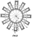
- Fig. 4 illustrates a preferred embodiment of a multi-segment electric motor, in which the stators 10 and rotors 12 are located around a circular path 24.
- the individual stators 10 and rotors 12 are essentially identical to those of previous embodiments, and may include access slots or other rotor access means as previously described.
- the individual stators 10 and rotors 12 are spaced substantially equiangularly around the circular path 24 in fixed angular relationship to one another.
- the rotational axes of the rotors 12 are tangential to the circular path 24.
- the general arrangement of the stators and rotors may be described as "toroidal" for convenience.
- the circular path along which the stators and rotors are arranged defines a closed loop.
- the rotors 12 are arranged to be translatable around the circular path 24, this allows any individual rotor 12 to be aligned with an access location (that is, for example, a stator having an access slot or a gap in the series of stators), while the other rotors 12 remain aligned with respective stators 10. This may also be achieved using closed loop paths which are non-circular.
- translation of the rotors around the circular path 24 amounts to rotation of the rotors about a common, central axis 26 extending at right angles to the plane of the path 24.
- Fig. 5 shows a further developed example of a toroidal machine as shown in Fig. 4, in which the rotors 12 are all mounted to a common, central hub 28 for rotation about the central axis 26 relative to the stators.
- Each rotor 12 may be adapted to incorporate or support one or more objects, samples or sample holders, to be centrifuged by rotation of the rotor about its rotational axis.
- the rotors may be rotated about their common, central axis 26 whilst the individual rotors 12 rotate about their individual rotational axes. This allows individual rotors to be presented to access locations for the loading or unloading of objects or samples, whilst the other rotors continue to rotate about their rotational axes.
- the continuous mode of operation provided by such apparatus is advantageous in comparison with conventional centrifuges, in which all objects or samples are mounted on a single centrifuge rotor, so that the entire rotor has to be stopped in order to allow the loading and unloading of individual objects or samples.
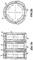
- Fig. 6 shows an example of stator/rotor combination in which the rotor 12 is provided with a slot, recess or the like 30, adapted to hold an object, sample or sample holder.
- the sample slot 30 may be aligned with an access slot 20 in the stator body 10 for loading and unloading.
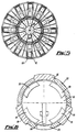
- FIG. 7 illustrates a further example of a toroidal, multi-segment centrifuge apparatus in accordance with the second aspect of the invention.
- a stator torus comprises a plurality of stator segments 50 having stator windings 52 formed thereon.
- the stator segments 50 together make up the series of stators spaced around the length of the torus, and are arranged such that a continuous slot 54 is formed around the inner circumference of the torus allowing access to the interior of the torus.
- Each rotor 56 is mounted on the end of a support arm 58 which extends from a central hub (not shown), through the slot 54 into the interior of the torus.
- the rotor 56 is mounted for rotation relative to the support arm 58 about its rotational axis, which extends tangentially to the circular path extending around the interior axis of the torus. Rotation of the central hub thus causes the rotors to be translated along the circular path for presentation to a loading/unloading station (as previously described, not shown in Fig. 7) as required.
- the rotor 56 is itself configured as a holder for a sample container 60 in the form of a test tube or the like. It will be appreciated that the configuration of the rotor and the sample holding arrangement provided thereby may be varied widely according to need.
- Figs. 8 to 12 show a further embodiment of a multi-segment motor adapted for use as a centrifuge apparatus.
- Figs. 8 to 10 illustrate the arrangement of the rotors/sample holders 100, which are again disposed around a circular path.
- the rotors 100 are supported by a peripheral structure extending around the outside of the circular path.
- the peripheral structure comprises an annular ring member 102 positioned above or below the centres of rotation of the rotors 100, preferably (but not necessarily) by a distance slightly greater than the rotor radius.
- a plurality of vertically extending brackets 104 are secured to one surface of the annular ring 100, and a corresponding plurality of generally triangular arms 106 are secured to and extend inwardly from the brackets 104, such that a parallel-sided gap is defined between each pair of adjacent arms 106.
- a vertically extending bearing assembly 108 is secured to each of the arms 106 adjacent the innermost end thereof.
- Each of the rotor bodies 100 is rotatably mounted in one of the gaps between adjacent arms 106, supported between the bearing assemblies 108 thereof. As is best seen in Figs. 9 and 10, each of the rotor bodies 100 itself includes a pair of bearings 110, the rotor body being rotatably supported by a pair of pins 112 engaging the rotor bearings 110 and the bearing assemblies 108 of the peripheral structure.
- the rotor bodies 100 each encapsulate a plurality of permanent magnets 114 and include means for receiving an object or sample to be centrifuged, such as a cylindrical bore 116 for receiving a sample tube 118 (Fig. 10).
- the peripheral structure is mounted on a suitable support structure (not shown) for rotation relative thereto about the centre of the circular path, such as by means of a peripheral friction drive schematically indicated by reference numeral 120 in Fig. 8, in which a sample loading/unloading location is also indicated by shaded area 122.
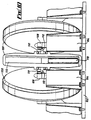
- the arrangement of the stator is illustrated in Figs 11 and 12.
- the stator 124 may have a generally toroidal configuration constructed in a manner similar to that shown in Fig. 7, having a continuous slot around its circumference allowing the arms 106 of the peripheral structure to extend into the interior of the stator 124 to support the rotor bodies 100 therein.
- a gap would be formed in the stator torus at the loading/unloading location 122 of Fig. 8.
- the centrifuge apparatus in accordance with the invention is preferably configured such that the rotors are translated around a closed-loop path, and most preferably a circular path, the path need not be a closed loop.
- the apparatus might alternatively be configured such that the rotors are translated from a first end to a second end of a linear or non-linear path, with transport means being provided to return each rotor to the first end as it arrives at the second end.
- the centrifuge apparatus is implemented using a multi-segment motor arrangement as described herein, it might alternatively be implemented by using a plurality of individual centrifuge devices arranged for translation along the required path past a loading/unloading station.
- the planes of rotation of the motors need not necessarily be disposed at right angles to the path, but might alternatively be at some other angle or parallel to the path (in the case of a closed-loop path, to the plane of the path).
- the invention might also be implemented by means of a plurality of centrifuge devices and a robotic loading/unloading device which moves relative to the centrifuge devices.
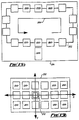
- FIG. 13(a) shows a plurality of centrifuge devices 200 arranged along a closed-loop path 202, for translation along the path in the direction of the arrow 204 past a loading/unloading station 206.
- Fig. 13(b) shows an array of centrifuge devices 210, which are fixed in location and which are loaded and unloaded by means of a robotic device 212 adapted for translational movement in the X-Y plane relative to the centrifuge devices 210, as indicated by the arrows X and Y.
- a centrifuge device comprises a rotor body adapted for rotation about a rotational axis and adapted to hold at least one sample for the purpose of centrifuging the sample. It is also preferred that the centrifuge devices are all mounted on a common chassis or in a common enclosure, as in the examples of Figs. 5 to 12 or as indicated schematically by boxes 214 and 216 in Figs. 13(a) and 13(b).
- each centrifuge device is configured for rotation in a vertical plane about a horizontal axis of rotation and that each centrifuge device is adapted to hold a single sample. It will be understood that any one of a variety of schemes might be used to control the operation of the centrifuge devices and any associated load/unload devices. The various possibilities will be apparent to those skilled in the art and are not described in detail herein.
- the multi-segment electric motor in accordance with the second aspect of the invention might also be used in other applications, such as multi-disk disk drives for data-carrying disks such as magnetic or optical disks.
Landscapes
- Engineering & Computer Science (AREA)
- Power Engineering (AREA)
- Centrifugal Separators (AREA)
Applications Claiming Priority (3)
| Application Number | Priority Date | Filing Date | Title |
|---|---|---|---|
| GBGB9523141.1A GB9523141D0 (en) | 1995-11-11 | 1995-11-11 | Improvements in or relating to electric motors and centrifugal apparatus |
| GB9523141 | 1995-11-11 | ||
| PCT/GB1996/002748 WO1997018022A2 (fr) | 1995-11-11 | 1996-11-08 | Ameliorations concernant des moteurs electriques et un appareil de centrifugation |
Publications (1)
| Publication Number | Publication Date |
|---|---|
| EP0979678A2 true EP0979678A2 (fr) | 2000-02-16 |
Family
ID=10783767
Family Applications (2)
| Application Number | Title | Priority Date | Filing Date |
|---|---|---|---|
| EP99115796A Withdrawn EP0979678A2 (fr) | 1995-11-11 | 1996-11-08 | Améliorations relatives aux moteurs électriques et aux appareils centrifuges |
| EP96937433A Expired - Lifetime EP0859666B1 (fr) | 1995-11-11 | 1996-11-08 | Ameliorations concernant des moteurs electriques et un appareil de centrifugation |
Family Applications After (1)
| Application Number | Title | Priority Date | Filing Date |
|---|---|---|---|
| EP96937433A Expired - Lifetime EP0859666B1 (fr) | 1995-11-11 | 1996-11-08 | Ameliorations concernant des moteurs electriques et un appareil de centrifugation |
Country Status (9)
| Country | Link |
|---|---|
| US (1) | US6033355A (fr) |
| EP (2) | EP0979678A2 (fr) |
| JP (1) | JP2000500065A (fr) |
| AT (1) | ATE189412T1 (fr) |
| AU (1) | AU7502796A (fr) |
| DE (1) | DE69606547T2 (fr) |
| ES (1) | ES2146028T3 (fr) |
| GB (1) | GB9523141D0 (fr) |
| WO (1) | WO1997018022A2 (fr) |
Cited By (2)
| Publication number | Priority date | Publication date | Assignee | Title |
|---|---|---|---|---|
| WO2007138274A1 (fr) * | 2006-05-26 | 2007-12-06 | Goodwin, Parvaneh | Appareil pour appliquer une force d'accélération |
| EP1952890A2 (fr) | 2007-01-30 | 2008-08-06 | Ortho Clinical Diagnostics Inc. | Centrifugeuse et incubateur à accès aléatoire |
Families Citing this family (3)
| Publication number | Priority date | Publication date | Assignee | Title |
|---|---|---|---|---|
| EP1155301A1 (fr) | 1999-01-29 | 2001-11-21 | Genomic Instrumentation Services, Inc. | Centrifugeuse de groupements ordonnes d'echantillons |
| US20030091473A1 (en) * | 2001-02-08 | 2003-05-15 | Downs Robert Charles | Automated centrifuge and method of using same |
| US9039992B2 (en) * | 2011-06-06 | 2015-05-26 | Abbott Laboratories | Apparatus for closed tube sampling and open tube sampling for automated clinical analyzers |
Family Cites Families (5)
| Publication number | Priority date | Publication date | Assignee | Title |
|---|---|---|---|---|
| GB1337424A (en) * | 1970-10-08 | 1973-11-14 | Rohe Scientific Corp | Automated centrifuging apparatus |
| GB1413987A (en) * | 1972-03-15 | 1975-11-12 | Hall Thermotank Int Ltd | Heat exchangers |
| DE2252505A1 (de) * | 1972-10-26 | 1974-05-09 | Philips Patentverwaltung | Rotationshohlkoerper, insbesondere um seine laengsachse umlaufender zylinder |
| US3838809A (en) * | 1973-04-16 | 1974-10-01 | M Williams | Automatic serum preparation station |
| US4233532A (en) * | 1978-07-10 | 1980-11-11 | Esters Ernie B | Modular dynamoelectric machine |
-
1995
- 1995-11-11 GB GBGB9523141.1A patent/GB9523141D0/en active Pending
-
1996
- 1996-11-08 EP EP99115796A patent/EP0979678A2/fr not_active Withdrawn
- 1996-11-08 ES ES96937433T patent/ES2146028T3/es not_active Expired - Lifetime
- 1996-11-08 AT AT96937433T patent/ATE189412T1/de not_active IP Right Cessation
- 1996-11-08 JP JP9518652A patent/JP2000500065A/ja active Pending
- 1996-11-08 WO PCT/GB1996/002748 patent/WO1997018022A2/fr not_active Ceased
- 1996-11-08 DE DE69606547T patent/DE69606547T2/de not_active Expired - Fee Related
- 1996-11-08 US US09/068,425 patent/US6033355A/en not_active Expired - Fee Related
- 1996-11-08 EP EP96937433A patent/EP0859666B1/fr not_active Expired - Lifetime
- 1996-11-08 AU AU75027/96A patent/AU7502796A/en not_active Abandoned
Cited By (3)
| Publication number | Priority date | Publication date | Assignee | Title |
|---|---|---|---|---|
| WO2007138274A1 (fr) * | 2006-05-26 | 2007-12-06 | Goodwin, Parvaneh | Appareil pour appliquer une force d'accélération |
| EP1952890A2 (fr) | 2007-01-30 | 2008-08-06 | Ortho Clinical Diagnostics Inc. | Centrifugeuse et incubateur à accès aléatoire |
| EP1952890A3 (fr) * | 2007-01-30 | 2012-06-20 | Ortho Clinical Diagnostics Inc. | Centrifugeuse et incubateur à accès aléatoire |
Also Published As
| Publication number | Publication date |
|---|---|
| EP0859666B1 (fr) | 2000-02-02 |
| ES2146028T3 (es) | 2000-07-16 |
| WO1997018022A3 (fr) | 1997-09-04 |
| WO1997018022A2 (fr) | 1997-05-22 |
| DE69606547D1 (de) | 2000-03-09 |
| DE69606547T2 (de) | 2000-09-14 |
| AU7502796A (en) | 1997-06-05 |
| GB9523141D0 (en) | 1996-01-10 |
| US6033355A (en) | 2000-03-07 |
| EP0859666A2 (fr) | 1998-08-26 |
| JP2000500065A (ja) | 2000-01-11 |
| ATE189412T1 (de) | 2000-02-15 |
Similar Documents
| Publication | Publication Date | Title |
|---|---|---|
| US5157295A (en) | Under-the-hub disk drive spin motor | |
| US5675196A (en) | High speed ten pole/twelve slot D.C. brushless motor with minimized net radial force and low cogging torque | |
| US4970422A (en) | Device with a thrust bearing | |
| US3974406A (en) | Electrical machine | |
| JP2001204162A (ja) | 次同期リラクタンス電気機械 | |
| US5652473A (en) | Rotary assembly including in particular radial support means and a magnetic axial abutment | |
| US6033355A (en) | Centrifuge with a plurality of individual centrifuge devices | |
| JPH06170675A (ja) | 回転電機装置 | |
| US5462470A (en) | Grinding wheel spindle assembly | |
| JPH0197152A (ja) | 磁石装置 | |
| JP7052920B2 (ja) | 真空ポンプ | |
| USRE35702E (en) | Compact motor mount for information storage devices | |
| CN1178609A (zh) | 具有最小净余径向力和低齿槽效应转矩的高速十极/十二槽直流无刷电动机 | |
| JPH10257728A (ja) | 同心多軸モータ | |
| JP3255236B2 (ja) | 2自由度アクチュエータ | |
| JPH0216390A (ja) | ターボ分子ポンプ | |
| EP0454685B1 (fr) | Moteur de rotation pour unite de disques sous le moyeu | |
| JPS58186144A (ja) | X線管装置 | |
| JPH0746802A (ja) | 電動モータ | |
| JPH0427404B2 (fr) | ||
| JPH0667168B2 (ja) | 非接触複動型アクチユエ−タ | |
| JPH0798017A (ja) | 磁気軸受装置 | |
| JP2979083B2 (ja) | 回転検出器における回転トランス構造 | |
| JPH03284139A (ja) | 回転体の駆動支持機構 | |
| CN115395754A (zh) | 一种直流电机和无刷直流电机 |
Legal Events
| Date | Code | Title | Description |
|---|---|---|---|
| PUAI | Public reference made under article 153(3) epc to a published international application that has entered the european phase |
Free format text: ORIGINAL CODE: 0009012 |
|
| AK | Designated contracting states |
Kind code of ref document: A2 Designated state(s): AT BE CH DE DK ES FI FR GB GR IE IT LI LU MC NL PT SE |
|
| AX | Request for extension of the european patent |
Free format text: AL;LT;LV;RO;SI |
|
| STAA | Information on the status of an ep patent application or granted ep patent |
Free format text: STATUS: THE APPLICATION IS DEEMED TO BE WITHDRAWN |
|
| 18D | Application deemed to be withdrawn |
Effective date: 19961108 |