EP0980072A1 - Changeur de disque - Google Patents
Changeur de disque Download PDFInfo
- Publication number
- EP0980072A1 EP0980072A1 EP98115008A EP98115008A EP0980072A1 EP 0980072 A1 EP0980072 A1 EP 0980072A1 EP 98115008 A EP98115008 A EP 98115008A EP 98115008 A EP98115008 A EP 98115008A EP 0980072 A1 EP0980072 A1 EP 0980072A1
- Authority
- EP
- European Patent Office
- Prior art keywords
- disc
- turntable
- trays
- casing
- designated
- Prior art date
- Legal status (The legal status is an assumption and is not a legal conclusion. Google has not performed a legal analysis and makes no representation as to the accuracy of the status listed.)
- Granted
Links
Images


Classifications
-
- G—PHYSICS
- G11—INFORMATION STORAGE
- G11B—INFORMATION STORAGE BASED ON RELATIVE MOVEMENT BETWEEN RECORD CARRIER AND TRANSDUCER
- G11B17/00—Guiding record carriers not specifically of filamentary or web form, or of supports therefor
- G11B17/02—Details
- G11B17/021—Selecting or spacing of record carriers for introducing the heads
-
- G—PHYSICS
- G11—INFORMATION STORAGE
- G11B—INFORMATION STORAGE BASED ON RELATIVE MOVEMENT BETWEEN RECORD CARRIER AND TRANSDUCER
- G11B17/00—Guiding record carriers not specifically of filamentary or web form, or of supports therefor
- G11B17/22—Guiding record carriers not specifically of filamentary or web form, or of supports therefor from random access magazine of disc records
- G11B17/221—Guiding record carriers not specifically of filamentary or web form, or of supports therefor from random access magazine of disc records with movable magazine
- G11B17/223—Guiding record carriers not specifically of filamentary or web form, or of supports therefor from random access magazine of disc records with movable magazine in a vertical direction
-
- G—PHYSICS
- G11—INFORMATION STORAGE
- G11B—INFORMATION STORAGE BASED ON RELATIVE MOVEMENT BETWEEN RECORD CARRIER AND TRANSDUCER
- G11B33/00—Constructional parts, details or accessories not provided for in the other groups of this subclass
- G11B33/02—Cabinets; Cases; Stands; Disposition of apparatus therein or thereon
- G11B33/08—Insulation or absorption of undesired vibrations or sounds
Definitions
- This invention relates to a disc changer apparatus for selecting one of information recording discs (for example, compact discs) and reproducing information from the selected disc.
- information recording discs for example, compact discs
- information recording discs such as compact discs are placed on trays respectively.
- the trays are arranged in a stack.
- One of the discs is selected in response to user's request.
- the selected disc is set on a turntable.
- the selected disc is rotated while being accessed by an information reading head. Accordingly, the disc changer apparatus is operated in a playback mode, and information is reproduced from the selected disc.
- a turntable In a disc changer apparatus with an overlap arrangement, a turntable can be moved into and out of regions between trays.
- the turntable is connected to one end of a swing plate.
- the other end of the swing plate is connected via a shaft to an elevator plate or a fixed plate.
- the swing plate is supported on a cantilever basis.
- the cantilever support tends to cause the turntable to be vibrated in response to an external force. The vibration of the turntable interferes with reproduction of information from a disc on the turntable.
- a first aspect of this invention provides a disc changer apparatus comprising a casing; a plurality of trays contained in the casing for carrying discs respectively; first means for holding and arranging the trays in a stack; second means for expanding a region between a designated one of the trays and a tray immediately above the designated tray; third means for pushing a disc on the designated tray; a turntable; fourth means for moving the turntable into the region expanded by the second means to place the turntable below the disc which has been pushed by the third means; wherein the fourth means comprises a shaft, a base plate supported within the casing via the shaft, a damper, and a chassis connected to The base plate via the damper and carrying the turntable.
- a second aspect of this invention is based on the first aspect thereof, and provides a disc changer apparatus wherein the damper extends between the shaft and the turntable as viewed from above.
- a third aspect of this invention provides a disc changer apparatus comprising a plurality of trays for carrying discs respectively; a movable base plate; a damper; a chassis connected to the base plate via the damper; a turntable provided on the chassis; and means for selecting one disc from among the discs on the trays and placing the selected disc on the turntable.
- a fourth aspect of this invention is based on the third aspect thereof, and provides a disc changer apparatus further comprising an information pickup head provided on the chassis.
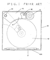
- the prior-art disc changer apparatus includes a box-shaped casing 40 which has a front panel 40A.
- the front panel 40A is formed with a disc insertion opening via which a disc 42 can be moved into and out of the casing 40.
- the casing 40 contains a plurality of trays extending in parallel to each other. The trays are arranged in a stack. Rollers 41 located in the casing 40 are driven by a motor. As a disc 42 is moved into the casing 40 via the disc insertion opening, the disc 42 is fed by the rollers 41 until being placed on one of the trays. Generally, different discs are placed on the trays respectively.
- the prior-art disc changer apparatus of Fig. 1 has a swing plate 45 whose one end is rotatably supported on a bottom panel of the casing 40 via a shaft 44.
- the other end of the swing plate 45 rotatably holds a turntable 43.
- An optical pickup head 46 provided on the swing plate 45 can read out information from a disc on the turntable 43.
- the optical pickup head 46 movably extends near the turntable 43.
- the swing plate 45 extends outward of the trays when being in its rest position.
- the swing plate 45 is rotated about the shaft 44 from its rest position to its operative position.
- the turntable 43 moves to a region below the designated disc. Then, the turntable 43 engages the designated disc, and rotates the designated disc to start reproduction of information therefrom. In this way, one of the discs is selected in response to user's request, and the selected disc is subjected to playback.
- the swing plate 45 is supported on a cantilever basis.
- the cantilever support tends to cause the turntable 43 and the optical pickup head 46 to be vibrated in response to an external force.
- the vibrations of the turntable 43 and the optical pickup head 46 interfere with the reproduction of information from the selected disc.
- a disc changer apparatus of an embodiment of this invention includes a box-shaped casing 1 which has a front panel 1A. A central portion of the front panel 1A is formed with a disc insertion opening via which a disc 3 can be moved into and out of the casing 1.
- Disc loading rollers 2 located in the casing 1 near the disc insertion opening are rotated by a roller drive mechanism (not shown). The rollers 2 operate to feed a disc 3. The rollers 2 enable a disc 3 to be inserted into and ejected from the casing 1 via the disc insertion opening.
- a plurality of trays 4 are located in a corner region of the interior of the casing 1 which are defined between a back panel 1B and a right-hand side panel 1C of the casing 1.
- the trays 4 have a semicircular or semicircumferential shape.
- the trays 4 are stacked along the vertical direction of the casing 1. Generally, discs 3 are placed on and received by the trays 4 respectively.
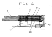
- An upper metal plate 5A extends above the uppermost tray 4.
- a lower metal plate 5B extends below the lowermost tray 4.
- Each of the metal plates 5A and 5B and the tray 4 has three holes.
- Three tray guide shafts fixed between an upper panel and a lower panel of the casing 1 extend through the holes of the metal plates 5A and 5B and the tray 4. The metal plates 5A and 5B and the tray 4 can move vertically while being guided by the tray guide shafts.
- the casing 1 contains a lever 6 which is supported via a pin 6A.
- the pin 6A engages one end of the lever 6.
- the lever 6 can rotate about the pin 6A.
- the other end of the lever 6 rotatably holds a roller 7.
- the lever 6 is urged by a spring (not shown) in the clockwise direction as viewed in Fig. 2.
- the disc 3 is fed by the rollers 2 toward the back panel 1B of the casing 1, and the circumference of the disc 3 meets the roller 7.
- the roller 7 changes the direction of the feed of the disc 3 toward the trays 4. Then, the disc 3 reaches one of the trays 4, being placed thereon and received thereby.
- a helical spring 8 extends vertically within the casing 1. An upper end of the helical spring 8 is connected to the upper metal plate 5A. A lower end of the helical spring 8 is connected to the lower metal plate 5B. The helical spring 8 urges the metal plates 5A and 5B toward each other, forcing and holding the trays 4 between the metal plates 5A and 5B as best shown in Fig. 4.
- a cam gear 9 is rotatably supported within the casing 1. As best shown in Fig. 7, the cam gear 9 has a spiral cam groove 9A into which projections of the trays 4 and the metal plates 5A and 5B fit.
- the cam gear 9 has a spiral ridge extending along the spiral cam groove 9A.
- a given portion 9B of the spiral ridge on the cam gear 9 has a width greater than the width of other portions 9C of the spiral ridge.
- the cam gear 9 has a projection 10 horizontally extending from the greater-width portion 9B of the spiral ridge.
- the projection 10 is integral with the greater-width portion 9B of the spiral ridge.
- Cam gears 11 and 12 are rotatably supported within the casing 1.
- the cam gears 11 and 12 are similar in structure to the cam gear 9. Specifically, each of the cam gears 11 and 12 has a spiral cam groove into which projections of the trays 4 and the metal plates 5A and 5B fit.
- Each of the cam gears 11 and 12 has a spiral ridge extending along the spiral cam groove. A given portion of the spiral ridge on each of the cam gears 11 and 12 has a width greater than the width of other portions of the spiral ridge.
- the cam gears 9, 11, and 12 are connected to a motor (not shown) via a power transmission arrangement.
- the cam gears 9, 11, and 12 are synchronously rotated by the motor.
- Cam gears 13 and 14 are rotatably supported within the casing 1 near the cam gears 11 and 12 respectively.
- Each of the cam gears 13 and 14 has a spiral cam groove into which projections of the trays 4 and the metal plates 5A and 5B fit.
- Each of the cam gears 13 and 14 has a spiral ridge extending along the spiral cam groove. Given portions of the ridges on the cam gears 13 and 14 have widths greater than the widths of the ridges on the cam gears 11 and 12.
- the cam gears 13 and 14 are connected to a motor (not shown) via a power transmission arrangement. The cam gears 13 and 14 are synchronously rotated by the motor.
- the related projections of the trays 4 and the metal plates 5A and 5B relatively slide along the spiral cam grooves therein and thus relatively move along the spiral ridges thereon.
- the trays 4 and the metal plates 5A and 5B are moved vertically while the regions among the trays 4 and the metal plates 5A and 5B are sequentially expanded and contracted.
- the greater-width portions of the spiral ridges on the cam gears 13 and 14 cause the expansions of the regions among the trays 4 and the metal plates 5A and 5B.
- the degree of the region expansions provided by the cam gears 13 and 14 is greater than the degree of the region expansions provided by the cam gears 9, 11, and 12.
- Fig. 5 shows an example of conditions of the trays 4 and discs thereon which occur when the disc changer apparatus is in a playback operation state.
- one of the regions among the trays 4 and the metal plates 5A and 5B is greatly expanded by the cam gears 13 and 14.
- a base plate or a substrate 15 is rotatably supported on the upper surface of the lower panel of the casing 1 via a shaft 16.
- the base plate 15 is rotated about the shaft 16 by a drive mechanism (not shown).
- a chassis 18 is supported on the base plate 15 via three dampers 17 made of rubber.
- An optical pickup head 19 is movably connected to the chassis 18.
- a feed screw can move the optical pickup head 19 relative to the chassis 18 in opposite directions "A".
- the optical pickup head 19 has an optical system including a light emitting element (a laser element), a photosensitive element, and an objective lens 20.
- the light emitting element When the disc changer apparatus is in its playback operation state, the light emitting element outputs laser light.
- the laser light outputted from the light emitting element passes through the objective lens 20 before being applied to a disc 3 on a turntable 21 which will be explained later.
- the laser light is reflected by the disc 3, forming return light which carries information recorded on the disc 3.
- the return light passes through the objective lens 20, and then reaches the photosensitive element.
- the photosensitive element converts the return light into an electric signal containing the information recorded on the disc 3.
- the photosensitive element outputs the electric signal to a signal processing circuit (not shown) for reproducing the information recorded on the disc 3.
- a turntable 21 is rotatably supported on the chassis 18.
- the turntable 21 is directly coupled to the rotational shaft of a motor 22 which has a body attached to the lower surface of the chassis 18.
- the turntable 21 is rotated by the motor 22.
- the turntable 21 has claws 23 which are moved between closed positions and open positions by a claw drive mechanism. When a disc 3 is absent from the turntable 21, the claws 23 are in their closed positions.
- the claw drive mechanism outwardly forces the claws 23 into their open positions at which the claws 23 firmly holds the disc 23 on the turntable 21.
- the claws 23 operate to fix the disc 23 to the turntable 21.
- the disc 3 on the turntable 21 is accessed by the optical pickup head 19.
- the directions "A" of the movement of the optical pickup head 19 relative to the chassis 18 agree with radial directions of the disc 3 on the turntable 21.
- the casing 1 contains a disc pushing lever 24 slidably held by an end of a shaft 25.
- a drive mechanism (not shown) moves the disc pushing lever 24 clockwise and counterclockwise as viewed in Fig. 2.
- the disc pushing lever 24 moves clockwise from its rest position, an end of the disc pushing lever 24 enters the stack of the trays 4 and meets the circumferential surface of a disc 3 on one of the trays 4. Then, the disc pushing lever 24 forces the disc 3 toward the center of the interior of the casing 1.
- the disc 3 is placed on the turntable 21. Subsequently, the disc 3 is fixed to the turntable 21, and is rotated thereby.
- the disc changer apparatus of Figs. 2-9 operates as follows.
- the cam gears 9, 11, and 12 are rotated so that the tray 4 which carries the designated disc 3 is vertically moved to a given position where the disc push lever 24 can meet the designated disc 3.
- the disc push lever 24 is moved clockwise as viewed in Fig. 2.
- the disc pushing lever 24 meets the designated disc 3 and forces the designated disc 3 to a predetermined position.
- a hold mechanism (not shown) retains the designated disc 3.
- the cam gears 13 and 14 are rotated so that the two ends of the tray 4 which carries the designated disc 3 are displaced downward.
- the hold mechanism continues to retain the designated disc 4.
- the two ends of the tray 4 separate from the designated disc 3 by a large distance.
- the base plate 15 is rotated about the shaft 16.
- the chassis 18, the optical pickup head 19, and the turntable 21 move together with the base plate 15.
- the turntable 21 enters the region between the designated disc 3 and the related tray 4.
- the turntable 21 is moved to a preset position directly below the designated disc 3.
- the designated disc 3 is placed on the turntable 21 while being released from the hold mechanism.
- the claws 23 on the turntable 21 are outwardly forced to their open positions so that the claws 23 fix the designated disc 3 to the turntable 21.
- the turntable 21 is rotated by the motor 22.
- the designated disc 3 rotates together with the turntable 21.
- the optical pickup head 19 reads out information therefrom.
- the optical pickup head 19 and the turntable 21 are provided on the chassis 18.
- the chassis 18 is supported on the base plate 15 via the dampers 17.
- the dampers 17 suppress vibrations of the optical pickup head 19 and the turntable 21.
- the base plate 15 is supported on the lower panel of the casing 1 via the shaft 16.
- the base plate 15 can rotate about the shaft 16.
- At least one of the dampers 17 extends between the shaft 16 and the turntable 21 as viewed from above.
- the cantilever support for the turntable 21 has a relatively short arm which is effective in preventing vibrations of the turntable 21.
Landscapes
- Automatic Disk Changers (AREA)
Priority Applications (5)
| Application Number | Priority Date | Filing Date | Title |
|---|---|---|---|
| JP19814297A JP3536599B2 (ja) | 1997-07-24 | 1997-07-24 | ディスクチェンジャー装置 |
| US09/128,932 US6212156B1 (en) | 1997-07-24 | 1998-08-05 | Disc changer apparatus with vibration free turntable |
| CA002242048A CA2242048C (fr) | 1997-07-24 | 1998-08-06 | Appareil de changement de disque |
| EP98115008A EP0980072B1 (fr) | 1997-07-24 | 1998-08-10 | Changeur de disque |
| DE69832478T DE69832478T2 (de) | 1998-08-10 | 1998-08-10 | Plattenwechslervorrichtung |
Applications Claiming Priority (4)
| Application Number | Priority Date | Filing Date | Title |
|---|---|---|---|
| JP19814297A JP3536599B2 (ja) | 1997-07-24 | 1997-07-24 | ディスクチェンジャー装置 |
| US09/128,932 US6212156B1 (en) | 1997-07-24 | 1998-08-05 | Disc changer apparatus with vibration free turntable |
| CA002242048A CA2242048C (fr) | 1997-07-24 | 1998-08-06 | Appareil de changement de disque |
| EP98115008A EP0980072B1 (fr) | 1997-07-24 | 1998-08-10 | Changeur de disque |
Publications (2)
| Publication Number | Publication Date |
|---|---|
| EP0980072A1 true EP0980072A1 (fr) | 2000-02-16 |
| EP0980072B1 EP0980072B1 (fr) | 2005-11-23 |
Family
ID=33437099
Family Applications (1)
| Application Number | Title | Priority Date | Filing Date |
|---|---|---|---|
| EP98115008A Expired - Lifetime EP0980072B1 (fr) | 1997-07-24 | 1998-08-10 | Changeur de disque |
Country Status (4)
| Country | Link |
|---|---|
| US (1) | US6212156B1 (fr) |
| EP (1) | EP0980072B1 (fr) |
| JP (1) | JP3536599B2 (fr) |
| CA (1) | CA2242048C (fr) |
Cited By (4)
| Publication number | Priority date | Publication date | Assignee | Title |
|---|---|---|---|---|
| WO2004088653A1 (fr) | 2003-03-31 | 2004-10-14 | Clarion Co., Ltd. | Dispositif pour disques, dispositif de transport de disques et dispositif de charge de disques |
| US7100176B2 (en) | 2002-07-30 | 2006-08-29 | Matsushita Electric Industrial Co., Ltd. | Optical disk driving apparatus |
| EP1852863A4 (fr) * | 2005-01-20 | 2008-02-13 | Matsushita Electric Industrial Co Ltd | Dispositif de disque |
| EP1612786A4 (fr) * | 2003-03-31 | 2008-08-13 | Clarion Co Ltd | Support de disque, mecanisme de positionnement de disque et dispositif a disque |
Families Citing this family (5)
| Publication number | Priority date | Publication date | Assignee | Title |
|---|---|---|---|---|
| CN2369325Y (zh) * | 1999-05-21 | 2000-03-15 | 仪宝资讯股份有限公司 | 可消除碟片晃动及共振效应的载体托盘构造 |
| DE69927510T2 (de) * | 1999-06-22 | 2006-09-14 | Mitsubishi Denki K.K. | Plattenvorrichtung |
| JP4003357B2 (ja) * | 1999-09-29 | 2007-11-07 | ソニー株式会社 | ディスクの記録及び/又は再生装置 |
| JP4472450B2 (ja) | 2004-07-15 | 2010-06-02 | パナソニック株式会社 | 光ディスク装置 |
| JP4494230B2 (ja) | 2005-01-19 | 2010-06-30 | パナソニック株式会社 | ディスク装置 |
Citations (4)
| Publication number | Priority date | Publication date | Assignee | Title |
|---|---|---|---|---|
| US4841499A (en) * | 1987-02-24 | 1989-06-20 | Pioneer Electronic Corporation | Multi-disc player |
| EP0514607A1 (fr) * | 1991-05-24 | 1992-11-25 | Pioneer Electronic Corporation | Tourne-disques à chargement automatique du disque |
| US5481512A (en) * | 1992-06-30 | 1996-01-02 | Victor Company Of Japan, Ltd. | Separable magazine for accommodating discs and a disc player |
| US5682364A (en) * | 1993-12-15 | 1997-10-28 | Shinwa Kabushiki Kaisha | Magazine for read/write disks and method and device for reading and writing said disks |
Family Cites Families (10)
| Publication number | Priority date | Publication date | Assignee | Title |
|---|---|---|---|---|
| US5046059A (en) | 1987-08-22 | 1991-09-03 | Pioneer Electronic Corporation | Multiple disc player with mechanism for changing of discs |
| US4870518A (en) | 1988-02-26 | 1989-09-26 | Syquest Technology | Removable cartridge disc drive with radial arm voice coil actuator |
| JPH0828025B2 (ja) | 1989-05-08 | 1996-03-21 | アルパイン株式会社 | ディスクチェンジャ |
| JP2534922B2 (ja) | 1990-02-09 | 1996-09-18 | パイオニア株式会社 | 複数ディスク収納プレ―ヤ |
| JP2795075B2 (ja) | 1992-06-30 | 1998-09-10 | 日本ビクター株式会社 | ディスク自動演奏装置 |
| JP3551482B2 (ja) | 1994-08-26 | 2004-08-04 | ソニー株式会社 | ディスクプレーヤ装置 |
| US5936930A (en) * | 1996-04-17 | 1999-08-10 | Funai Electronic Co., Ltd. | Automatic disk changer |
| JP3514588B2 (ja) * | 1996-08-23 | 2004-03-31 | アルパイン株式会社 | ディスク装置 |
| JP3437383B2 (ja) * | 1996-08-28 | 2003-08-18 | 松下電器産業株式会社 | ディスクチェンジャ |
| JP3434420B2 (ja) * | 1996-08-28 | 2003-08-11 | 松下電器産業株式会社 | ディスクチェンジャ |
-
1997
- 1997-07-24 JP JP19814297A patent/JP3536599B2/ja not_active Expired - Fee Related
-
1998
- 1998-08-05 US US09/128,932 patent/US6212156B1/en not_active Expired - Lifetime
- 1998-08-06 CA CA002242048A patent/CA2242048C/fr not_active Expired - Fee Related
- 1998-08-10 EP EP98115008A patent/EP0980072B1/fr not_active Expired - Lifetime
Patent Citations (4)
| Publication number | Priority date | Publication date | Assignee | Title |
|---|---|---|---|---|
| US4841499A (en) * | 1987-02-24 | 1989-06-20 | Pioneer Electronic Corporation | Multi-disc player |
| EP0514607A1 (fr) * | 1991-05-24 | 1992-11-25 | Pioneer Electronic Corporation | Tourne-disques à chargement automatique du disque |
| US5481512A (en) * | 1992-06-30 | 1996-01-02 | Victor Company Of Japan, Ltd. | Separable magazine for accommodating discs and a disc player |
| US5682364A (en) * | 1993-12-15 | 1997-10-28 | Shinwa Kabushiki Kaisha | Magazine for read/write disks and method and device for reading and writing said disks |
Cited By (19)
| Publication number | Priority date | Publication date | Assignee | Title |
|---|---|---|---|---|
| US7284248B2 (en) | 2002-07-30 | 2007-10-16 | Matsushita Electric Industrial Co., Ltd. | Optical disc driving apparatus |
| US7100176B2 (en) | 2002-07-30 | 2006-08-29 | Matsushita Electric Industrial Co., Ltd. | Optical disk driving apparatus |
| EP1406258A3 (fr) * | 2002-07-30 | 2007-04-25 | Matsushita Electric Industrial Co., Ltd. | Appareil pour l'entrainement des disques optiques |
| US7219356B2 (en) | 2002-07-30 | 2007-05-15 | Matsushita Electric Industrial Co., Ltd. | Optical disc driving apparatus |
| US7234148B2 (en) | 2002-07-30 | 2007-06-19 | Matsushita Electric Industrial Co., Ltd. | Optical disc driving apparatus |
| US7278145B2 (en) | 2002-07-30 | 2007-10-02 | Matsushita Electric Industrial Co. Ltd. | Optical disk driving apparatus |
| US7284247B2 (en) | 2002-07-30 | 2007-10-16 | Matsushita Electric Industrial Co., Ltd. | Optical disc driving apparatus |
| US7774802B2 (en) | 2003-03-31 | 2010-08-10 | Clarion Co., Ltd. | Disk holder, disk alignment mechanism and disk drive |
| EP1612786A4 (fr) * | 2003-03-31 | 2008-08-13 | Clarion Co Ltd | Support de disque, mecanisme de positionnement de disque et dispositif a disque |
| EP1612785A4 (fr) * | 2003-03-31 | 2008-08-13 | Clarion Co Ltd | Dispositif pour disques, dispositif de transport de disques et dispositif de charge de disques |
| US7685611B2 (en) | 2003-03-31 | 2010-03-23 | Clarion Co., Ltd. | Disk device, disk-transporting device, and disk-loading device |
| WO2004088653A1 (fr) | 2003-03-31 | 2004-10-14 | Clarion Co., Ltd. | Dispositif pour disques, dispositif de transport de disques et dispositif de charge de disques |
| US7836464B2 (en) | 2003-03-31 | 2010-11-16 | Clarion Co., Ltd. | Disk holder, disk alignment mechanism and disk drive |
| US7840971B2 (en) | 2003-03-31 | 2010-11-23 | Clarion Co., Ltd. | Disk holder, disk alignment mechanism and disk drive |
| US7913266B2 (en) | 2003-03-31 | 2011-03-22 | Clarion Co., Ltd. | Disk drive, disk feeding device, and disk loading mechanism |
| EP2325842A1 (fr) * | 2003-03-31 | 2011-05-25 | CLARION Co., Ltd. | Mécanisme d'alignement de disque |
| EP2328150A1 (fr) * | 2003-03-31 | 2011-06-01 | Clarion Co., Ltd. | Dispositif d'entrainement de disque et mécanisme de chargement de disque |
| US7971211B2 (en) | 2003-03-31 | 2011-06-28 | Clarion Co., Ltd. | Disk drive, disk feeding device, and disk loading mechanism |
| EP1852863A4 (fr) * | 2005-01-20 | 2008-02-13 | Matsushita Electric Industrial Co Ltd | Dispositif de disque |
Also Published As
| Publication number | Publication date |
|---|---|
| CA2242048C (fr) | 2001-07-03 |
| JP3536599B2 (ja) | 2004-06-14 |
| EP0980072B1 (fr) | 2005-11-23 |
| US6212156B1 (en) | 2001-04-03 |
| JPH1145490A (ja) | 1999-02-16 |
| CA2242048A1 (fr) | 2000-02-06 |
Similar Documents
| Publication | Publication Date | Title |
|---|---|---|
| US5812511A (en) | Disk recording and reproducing apparatus | |
| US5384760A (en) | Disk changer player with stocker between loading/unloading position and reproducing unit | |
| US6272093B1 (en) | Disk loading device and disk adaptor | |
| EP0450528A2 (fr) | Lecteur de disques | |
| CA2242048C (fr) | Appareil de changement de disque | |
| JP3088248B2 (ja) | ディスク再生装置 | |
| US6459674B1 (en) | Disc changer apparatus with vibration free turntable | |
| EP1246180B1 (fr) | Appareil de lecture de disque | |
| US7234148B2 (en) | Optical disc driving apparatus | |
| JPS63167492A (ja) | 種々の形式のディスクを走査するに好適なディスクレコードプレーヤ | |
| JP3528613B2 (ja) | ディスクチェンジャー装置 | |
| US6690627B2 (en) | System for reproducing a recorded disc | |
| JP3502766B2 (ja) | ディスク再生装置 | |
| US5524003A (en) | Disk-drive apparatus waith rattle-preventing cartridge magazine | |
| US6680882B2 (en) | System for reproducing a disc | |
| JPH11162068A (ja) | ディスク装置 | |
| JP3553425B2 (ja) | ディスクチェンジャー装置 | |
| GB2241104A (en) | Stopper for trays in a magazine of a cd player | |
| EP0955633A1 (fr) | Changeur de disques pour un appareil de lecture de disques | |
| JP3536690B2 (ja) | ディスクチェンジャー装置 | |
| JP3536671B2 (ja) | ディスクチェンジャー装置 | |
| JP3613012B2 (ja) | ディスクチェンジャー装置 | |
| EP0855708B1 (fr) | Appareil à disque | |
| JP2737913B2 (ja) | 情報記録再生装置 | |
| JP2599245B2 (ja) | ディスクチェンジャ付ディスクプレーヤ |
Legal Events
| Date | Code | Title | Description |
|---|---|---|---|
| PUAI | Public reference made under article 153(3) epc to a published international application that has entered the european phase |
Free format text: ORIGINAL CODE: 0009012 |
|
| 17P | Request for examination filed |
Effective date: 19980810 |
|
| AK | Designated contracting states |
Kind code of ref document: A1 Designated state(s): DE FR GB |
|
| AX | Request for extension of the european patent |
Free format text: AL;LT;LV;MK;RO;SI |
|
| AKX | Designation fees paid |
Free format text: DE FR GB |
|
| 17Q | First examination report despatched |
Effective date: 20041013 |
|
| GRAP | Despatch of communication of intention to grant a patent |
Free format text: ORIGINAL CODE: EPIDOSNIGR1 |
|
| GRAS | Grant fee paid |
Free format text: ORIGINAL CODE: EPIDOSNIGR3 |
|
| GRAA | (expected) grant |
Free format text: ORIGINAL CODE: 0009210 |
|
| AK | Designated contracting states |
Kind code of ref document: B1 Designated state(s): DE FR GB |
|
| REG | Reference to a national code |
Ref country code: GB Ref legal event code: FG4D |
|
| REF | Corresponds to: |
Ref document number: 69832478 Country of ref document: DE Date of ref document: 20051229 Kind code of ref document: P |
|
| ET | Fr: translation filed | ||
| PLBE | No opposition filed within time limit |
Free format text: ORIGINAL CODE: 0009261 |
|
| STAA | Information on the status of an ep patent application or granted ep patent |
Free format text: STATUS: NO OPPOSITION FILED WITHIN TIME LIMIT |
|
| 26N | No opposition filed |
Effective date: 20060824 |
|
| REG | Reference to a national code |
Ref country code: GB Ref legal event code: 746 Effective date: 20091221 |
|
| PGFP | Annual fee paid to national office [announced via postgrant information from national office to epo] |
Ref country code: DE Payment date: 20140806 Year of fee payment: 17 |
|
| PGFP | Annual fee paid to national office [announced via postgrant information from national office to epo] |
Ref country code: GB Payment date: 20140806 Year of fee payment: 17 |
|
| REG | Reference to a national code |
Ref country code: DE Ref legal event code: R119 Ref document number: 69832478 Country of ref document: DE |
|
| GBPC | Gb: european patent ceased through non-payment of renewal fee |
Effective date: 20150810 |
|
| REG | Reference to a national code |
Ref country code: FR Ref legal event code: PLFP Year of fee payment: 19 |
|
| PG25 | Lapsed in a contracting state [announced via postgrant information from national office to epo] |
Ref country code: DE Free format text: LAPSE BECAUSE OF NON-PAYMENT OF DUE FEES Effective date: 20160301 Ref country code: GB Free format text: LAPSE BECAUSE OF NON-PAYMENT OF DUE FEES Effective date: 20150810 |
|
| PGFP | Annual fee paid to national office [announced via postgrant information from national office to epo] |
Ref country code: FR Payment date: 20160712 Year of fee payment: 19 |
|
| REG | Reference to a national code |
Ref country code: FR Ref legal event code: ST Effective date: 20180430 |
|
| PG25 | Lapsed in a contracting state [announced via postgrant information from national office to epo] |
Ref country code: FR Free format text: LAPSE BECAUSE OF NON-PAYMENT OF DUE FEES Effective date: 20170831 |