EP0980732B1 - Méthode et appareil de forage de trous dans la paroi d' un cylindre - Google Patents
Méthode et appareil de forage de trous dans la paroi d' un cylindre Download PDFInfo
- Publication number
- EP0980732B1 EP0980732B1 EP99202184A EP99202184A EP0980732B1 EP 0980732 B1 EP0980732 B1 EP 0980732B1 EP 99202184 A EP99202184 A EP 99202184A EP 99202184 A EP99202184 A EP 99202184A EP 0980732 B1 EP0980732 B1 EP 0980732B1
- Authority
- EP
- European Patent Office
- Prior art keywords
- drilling
- module
- cylinder
- spindle
- modules
- Prior art date
- Legal status (The legal status is an assumption and is not a legal conclusion. Google has not performed a legal analysis and makes no representation as to the accuracy of the status listed.)
- Expired - Lifetime
Links
- 238000005553 drilling Methods 0.000 title claims description 96
- 238000000034 method Methods 0.000 title claims description 9
- 238000010586 diagram Methods 0.000 description 4
- 238000010276 construction Methods 0.000 description 3
- 238000003754 machining Methods 0.000 description 3
- 230000005540 biological transmission Effects 0.000 description 2
- 238000010420 art technique Methods 0.000 description 1
- 230000000712 assembly Effects 0.000 description 1
- 238000000429 assembly Methods 0.000 description 1
- 230000004886 head movement Effects 0.000 description 1
- 230000000284 resting effect Effects 0.000 description 1
Images


Classifications
-
- B—PERFORMING OPERATIONS; TRANSPORTING
- B23—MACHINE TOOLS; METAL-WORKING NOT OTHERWISE PROVIDED FOR
- B23B—TURNING; BORING
- B23B39/00—General-purpose boring or drilling machines or devices; Sets of boring and/or drilling machines
- B23B39/16—Drilling machines with a plurality of working-spindles; Drilling automatons
- B23B39/161—Drilling machines with a plurality of working-spindles; Drilling automatons with parallel work spindles
- B23B39/162—Drilling machines with a plurality of working-spindles; Drilling automatons with parallel work spindles having gear transmissions
-
- B—PERFORMING OPERATIONS; TRANSPORTING
- B23—MACHINE TOOLS; METAL-WORKING NOT OTHERWISE PROVIDED FOR
- B23B—TURNING; BORING
- B23B39/00—General-purpose boring or drilling machines or devices; Sets of boring and/or drilling machines
- B23B39/16—Drilling machines with a plurality of working-spindles; Drilling automatons
- B23B39/161—Drilling machines with a plurality of working-spindles; Drilling automatons with parallel work spindles
- B23B39/167—Drilling machines with a plurality of working-spindles; Drilling automatons with parallel work spindles having belt and chain transmissions
-
- Y—GENERAL TAGGING OF NEW TECHNOLOGICAL DEVELOPMENTS; GENERAL TAGGING OF CROSS-SECTIONAL TECHNOLOGIES SPANNING OVER SEVERAL SECTIONS OF THE IPC; TECHNICAL SUBJECTS COVERED BY FORMER USPC CROSS-REFERENCE ART COLLECTIONS [XRACs] AND DIGESTS
- Y10—TECHNICAL SUBJECTS COVERED BY FORMER USPC
- Y10T—TECHNICAL SUBJECTS COVERED BY FORMER US CLASSIFICATION
- Y10T408/00—Cutting by use of rotating axially moving tool
- Y10T408/03—Processes
-
- Y—GENERAL TAGGING OF NEW TECHNOLOGICAL DEVELOPMENTS; GENERAL TAGGING OF CROSS-SECTIONAL TECHNOLOGIES SPANNING OVER SEVERAL SECTIONS OF THE IPC; TECHNICAL SUBJECTS COVERED BY FORMER USPC CROSS-REFERENCE ART COLLECTIONS [XRACs] AND DIGESTS
- Y10—TECHNICAL SUBJECTS COVERED BY FORMER USPC
- Y10T—TECHNICAL SUBJECTS COVERED BY FORMER US CLASSIFICATION
- Y10T408/00—Cutting by use of rotating axially moving tool
- Y10T408/36—Machine including plural tools
- Y10T408/38—Plural, simultaneously operational tools
- Y10T408/3811—Plural, simultaneously operational tools with provision for adjustment of relationship of axes
-
- Y—GENERAL TAGGING OF NEW TECHNOLOGICAL DEVELOPMENTS; GENERAL TAGGING OF CROSS-SECTIONAL TECHNOLOGIES SPANNING OVER SEVERAL SECTIONS OF THE IPC; TECHNICAL SUBJECTS COVERED BY FORMER USPC CROSS-REFERENCE ART COLLECTIONS [XRACs] AND DIGESTS
- Y10—TECHNICAL SUBJECTS COVERED BY FORMER USPC
- Y10T—TECHNICAL SUBJECTS COVERED BY FORMER US CLASSIFICATION
- Y10T408/00—Cutting by use of rotating axially moving tool
- Y10T408/36—Machine including plural tools
- Y10T408/38—Plural, simultaneously operational tools
- Y10T408/3839—Plural, simultaneously operational tools with presser-foot
-
- Y—GENERAL TAGGING OF NEW TECHNOLOGICAL DEVELOPMENTS; GENERAL TAGGING OF CROSS-SECTIONAL TECHNOLOGIES SPANNING OVER SEVERAL SECTIONS OF THE IPC; TECHNICAL SUBJECTS COVERED BY FORMER USPC CROSS-REFERENCE ART COLLECTIONS [XRACs] AND DIGESTS
- Y10—TECHNICAL SUBJECTS COVERED BY FORMER USPC
- Y10T—TECHNICAL SUBJECTS COVERED BY FORMER US CLASSIFICATION
- Y10T408/00—Cutting by use of rotating axially moving tool
- Y10T408/36—Machine including plural tools
- Y10T408/385—Rotatable about parallel axes
Definitions
- the present invention relates to a method for drilling holes in the shell of a paper machine cylinder, according to the preamble of claim 1.
- the invention also concerns an apparatus for drilling holes in the shell of paper machine cylinder, according to the preamble of claim 2.
- EP-B-0448947 describes a method and an apparatus for on-site drilling of perforating holes in the shell of a cylinder, particularly a dryer cylinder, in a paper machine with the cylinder being unremoved from the paper machine.
- Said apparatus comprises a spindle box equipped with a plurality of spindle heads adapted driven by a drive motor.
- the spindle box houses the drive motor which is arranged to move the spindle box with regard to the framework of the drilling apparatus when the drills are actuated toward the cylinder surface to be machined.
- said apparatus includes a drilling jig adapted to support and tension the framework of said drilling apparatus between the guideways and the shell of the cylinder to be machined.
- the apparatus includes slide bushings arranged to guide the framework of the drilling apparatus along the guideway assembly when the apparatus is being moved into the next drilling position in the direction of the cylinder axis.
- the design of the apparatus uses guideways supported on the cylinder next to that being machined.
- EP-B-0545879 describes a further development of the above-outlined apparatus, whereby each spindle head is provided with a separate slide frame adapted individually movable in the lateral direction.
- FR-A-0448947 relates to a variable-configuration multi-spindle machining head, whereby the head, which can be fitted to a machine tool, translates a drive movement to a plurality of tool spindles each one mounted on a spindle housing, possibly associated with a relay housing and adjustable in terms of angular position about a mounting axis.
- a setting disk is mounted at the base of a drum surrounding the housings so that it can rotate about the overall axis of the head, and including grooves each of which is traversed by a hub of a spindle housing located on the movement output side.
- the rotation of the setting disk makes it possible synchronously to modify the distances between all the tools and the overall axis of the head.
- a method and an apparatus for drilling holes in the shell of a paper machine cylinder, according to the present invention are set forth in claim 1 and respectively in claim 2.
- the method and apparatus according to the invention offer a number of significant benefits.
- the use of multispindle drilling modules and the positioning technique of drilling modules by means of having the drilling modules made rotatable about their intermediate shafts can provide an extremely wide latitude in the position control of the drilling modules.
- the position control possibilities may be extended further by using drilling modules adapted rotatable about the central drive shaft of the module.
- the present construction facilitates drilling without drilling jigs.
- paper machine is used when reference is made to machines used in making a material web including a paper machine, a board machine or a cellulosic web dryer.
- cylinder is used when reference is made generally to cylindrical objects such as rolls, dryer cylinders and the like.
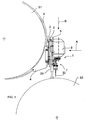
- FIG. 1 therein is shown a preferred embodiment of the apparatus 1 according to the invention in its operating position supported on the structures of a paper machine such as a first cylinder s1 of the paper machine.
- the cylinder s2 to be drilled is situated laterally offset below the first cylinder s1.
- the apparatus 1 includes a framework 2 with a construction supportable on the structures of the paper machine.
- the framework 2 is supported on the first cylinder s1 by means of support members 3, 4 such as curved plates 4 resting on the shell of the cylinder.
- the curved plates are further connected to the framework 2.
- the apparatus is anchored by means of fastening belts 5 to the surface of the first cylinder s1.
- the framework 2 will be aligned essentially parallel to the axis of the cylinder s1 at least over a portion of the cylinder width.
- the apparatus 1 includes a feed frame 6 which, supported by the framework 2, is adapted to be movable toward the surface of the cylinder s2 to be machined, said feed frame comprising a plurality of drilling modules 7 adapted to be driven by means of a drive unit 8.
- On the framework 2 are adapted guideways 9 along which the feed frame 6 can be moved in order to provide the feed movement of the drilling modules 7 as well as the withdrawal movement thereof outward from the cylinder surface after the completion of the drilling step.
- the drilling modules 7 include at least two spindle heads.
- the embodiment illustrated in Fig. 2 has six two-spindle drilling modules 7 adapted for simultaneous drive by means of a drive unit 8.
- Each drilling module 7 has a central drive shaft which in the embodiment illustrated in the diagrams is belt-driven.
- the belt drive train is accomplished by providing the drive shaft 10 with a belt drive pulley 11 and the drilling module 7 with belt idler pulleys 12, 13.
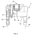
- a first gear wheel 14 (cf. Fig. 5 ), which is adapted to drive a gear transmission 16 of an intermediate shaft 15 that further drives a spindle shaft 17.
- each drilling module 7 includes two spindle heads 18, 18', driven in the above-described manner by the drive shaft 10 of the drilling module.
- At least one spindle head 18, 18' in each drilling module is arranged rotatable about an intermediate shaft 15, 15' of the drilling module arranged between the drive shaft 10 and the spindle head.
- the mutual distance of the spindle shaft centers 19, 19' from each other can be adjusted in each drilling module separately by means of rotating at least one spindle head 18, 18' in the drilling module about the intermediate shaft 15, 15' of the drilling module.
- the entire drilling module, or at least the spindle head housing the spindle shafts is arranged rotatable about the drive shaft 10, thus making it possible to control the drilling pattern produced by each drilling module 7. Resultingly, the spindle shaft centers 19, 19' of a two-spindle drilling module can be readily aligned on a desired line.
- Each drilling module 7 has means 20, 21 for locking the drilling module into a desired position.
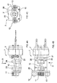
- the drilling module 7 includes a mounting plate 22 (cf. Fig. 4 ) of the spindle head 7', said mounting plate having arranged thereon the bearing assemblies 23, 24 of the drive shaft 10 as well as support elements 25 for mounting the belt idler pulleys 12, 13.
- the spindle head mounting plate 11 is provided with holes, slots or similar openings 26 for fixing the spindle head into a desired position by means of fasteners 20, 21 such as screws or bolts.
- the drilling modules 7 are mounted by their mounting plates 22 in a movable manner on a guideway 33 adapted on the feed frame 6. Resultingly, a still further facility of controlling the layout of the drilling pattern can be obtained by altering the position of the drilling modules 7 in the feed frame 6. In Fig. 2 , such a position control possibility is indicated by arrows.
- a drilling apparatus 1 is built on a framework 2.
- the framework 2 includes a mounting member 3 to which the curved backing plates 4 are connected.
- the framework consists of a body 2 including guideways for the movement of the feed frame 6, and an actuator assembly 27, 28 of the feed frame, capable of moving the feed frame 6 with respect to the drilling apparatus body 2.
- the actuator of the feed frame 6 comprises a conventional screw lift (jack) 27, driven by means of a drive motor 28.
- Into the feed frame 6 are adapted a number of parallel drilling modules 7, all driven by means of a common drive unit 8.
- the drive unit is mounted on the feed frame.
- the framework advantageously the body 2 thereof, is provided with support members 29, advantageously comprising pneumatic cylinders, which, prior to the machining operation, are driven against the surface of the cylinder s2 to be machined, whereby any possible play, that is, the instability in the bearings of the cylinder s1 and the support structures thereof acting as the mounting base of the drilling apparatus is minimized and the drilling operation itself becomes very stable.
- This arrangement prevents, for instance, unwanted movements of the drilling apparatus during the drilling operation, whereby the breaking of the drills 30 is eliminated.
- the drilling operation takes place as follows.
- the drilling apparatus is first mounted on the cylinder s1 next closest to the cylinder s2 to be machined by means of fastening belts.
- the spindle heads of the drilling modules 7 are next adjusted into a desired position and the spindle head 7' of the drilling module is rotated with respect to the drive shaft 10 if so needed. Furthermore, the mutual distances between the drilling modules 7 are set as required to obtain the desired drilling pattern.
- the support members 29 are driven against the surface of the cylinder s2 to be machined. With the help of the actuator assembly 27, 28, the feed frame 6 is moved toward the cylinder to be machined. Finally, the rotary drive unit 8 of the spindle heads 30 is switched on. After the completion of the drilling step, these actions are repeated in a reverse order.
- the cylinder s2 being machined is rotated between the drilling steps by means of a rotary drive system (not shown in the diagrams) about the cylinder shaft incrementally by a given angle into the next drilling position.
- a rotary drive system is described in patent publication EP-B-0448947 .
- such a rotary drive system can rotate the cylinder only by increments determined by the pitch of the gear wheel mounted in the drive unit. Hence, each different size of incremental angle of rotation would need a separate gear wheel.
- a conventional indexing wheel can be used to convert the increment angle of rotation into a suitable value.
- the cylinder being machined is locked into a fixed position for the duration of the machining step.
- the drive means 8 which advantageously is a conventional electric motor, transmits its power feed from the motor output shaft 31 via a belt transmission train 32 to the drive shafts 10 of the drilling modules 7, wherefrom the power feed is distributed individually to each of the spindle heads carrying the drills 30.
- Figs. 4A-4C is shown one of the drilling modules and in Fig. 5 one spindle head 7' of the drilling module.
- the spindle shaft centers 19, 19' are made rotatably adjustable about each of the intermediate shafts 15, 15', the number of which in the embodiment illustrated in the diagram is two.
- the position control of the drilling module is illustrated in schematic manner in Figs. 6A, 6B and 6C .
- Fig. 6A the mutual distance between the spindle shaft centers 19, 19' of the two-spindle head 7' is shown driven into the maximally outdistanced position.
- the spindle head 7' of the drilling module has not been rotated about the drive shaft 10.
- Fig. 6B both spindle shaft centers 19, 19' are shown rotated about the intermediate shaft 15, 15'.
- the drills are offset at a distance from the centerline of drilling.
- the drilling pattern may further be controlled by rotating the frame of the spindle head 7' about the center axis 10, whereby it is possible to bring the spindle shaft centers 19, 19' to the centerline of drilling, for instance.
Landscapes
- Engineering & Computer Science (AREA)
- Mechanical Engineering (AREA)
- Perforating, Stamping-Out Or Severing By Means Other Than Cutting (AREA)
- Drilling And Boring (AREA)
Claims (2)
- Procédé de perçage de trous dans l'enveloppe d'un cylindre de machine à papier, ledit cylindre demeurant dans sa position de fonctionnement dans une machine à papier, dans lequel procédé est utilisé un appareil à percer multibroches (1) équipé d'un système de réglage de la distance entre les centres de perçage des modules de perçage adjacents (7), dans lequel l'appareil à percer multibroches utilise des modules de perçage (7) d'au moins deux têtes de broche,
caractérisé en ce que la distance mutuelle des centres d'arbre de broche (19, 19') dans chaque module de perçage est ajustée en mettant en rotation au moins une tête de broche d'au moins un module de perçage autour d'un arbre intermédiaire (15, 15') disposé entre un arbre d'entraînement (10) et la tête de broche,
en ce que le dessin de perçage réalisé au moyen du module de perçage est en outre ajusté en mettant en rotation le corps du module de perçage, ou en variante, la tête de broche (7') du module de perçage autour de l'arbre d'entraînement central (10) du module de perçage, et
en ce que le dessin de perçage est en outre ajusté en modifiant la position mutuelle des modules de perçage adjacents (7) les uns par rapport aux autres. - Appareil de perçage de trous dans l'enveloppe d'un cylindre de machine à papier, ledit appareil comprenant un châssis stationnaire adapté pour pouvoir être supporté sur les structures de la machine à papier et un cadre d'alimentation adapté pour pouvoir être déplacé le long dudit châssis stationnaire radialement vers l'enveloppe dudit cylindre, ledit cadre d'alimentation portant une pluralité de modules de perçage adaptés pour pouvoir être mis en rotation au moyen d'une unité d'entraînement,
caractérisé en ce que les modules de perçage (7) comprennent un arbre d'entraînement (10), au moins deux têtes de broche et des arbres intermédiaires (15, 15') disposés entre l'arbre d'entraînement (10) et les têtes de broche, et
en ce qu'au moins une tête de broche (18, 18') dans chaque module de perçage est disposée de façon à pouvoir être mise en rotation autour de l'arbre intermédiaire (15, 15') du module de perçage,
en ce que le module de perçage (7) ou la tête de broche (7') est disposé(e) de façon à pouvoir être mis(e) en rotation autour de l'arbre d'entraînement central (10) du module et comprend des moyens de blocage dudit module ou de ladite tête dans une position souhaitée, et
en ce que le cadre d'alimentation (6) de l'appareil comprend une pluralité de modules de perçage, au moins certains des modules étant disposés de façon à pouvoir être déplacés dans la direction latérale.
Applications Claiming Priority (2)
| Application Number | Priority Date | Filing Date | Title |
|---|---|---|---|
| FI981598A FI109884B (fi) | 1998-07-13 | 1998-07-13 | Menetelmä ja laitteisto reikien poraamiseksi sylinterin vaippaan |
| FI981598 | 1998-07-13 |
Publications (3)
| Publication Number | Publication Date |
|---|---|
| EP0980732A2 EP0980732A2 (fr) | 2000-02-23 |
| EP0980732A3 EP0980732A3 (fr) | 2003-05-21 |
| EP0980732B1 true EP0980732B1 (fr) | 2008-03-12 |
Family
ID=8552184
Family Applications (1)
| Application Number | Title | Priority Date | Filing Date |
|---|---|---|---|
| EP99202184A Expired - Lifetime EP0980732B1 (fr) | 1998-07-13 | 1999-07-06 | Méthode et appareil de forage de trous dans la paroi d' un cylindre |
Country Status (5)
| Country | Link |
|---|---|
| US (1) | US6361254B1 (fr) |
| EP (1) | EP0980732B1 (fr) |
| CA (1) | CA2273305C (fr) |
| DE (1) | DE69938325T2 (fr) |
| FI (1) | FI109884B (fr) |
Families Citing this family (8)
| Publication number | Priority date | Publication date | Assignee | Title |
|---|---|---|---|---|
| US7066692B2 (en) * | 2003-01-16 | 2006-06-27 | Kuhn Jayme K | Dual chuck electrical hand drill |
| DE10329402A1 (de) * | 2003-06-28 | 2005-01-13 | Witzig & Frank Gmbh | Werkzeugmaschine |
| CN100434239C (zh) * | 2003-11-24 | 2008-11-19 | 怀特霍特解决方案公司 | 具有单驱动轴的手枪握把式工具 |
| US8382402B2 (en) * | 2008-12-16 | 2013-02-26 | General Electric Company | Drilling apparatus |
| US20120175366A1 (en) * | 2011-01-10 | 2012-07-12 | GM Global Technology Operations LLC | Vent hole alignment of temperature-pressure relief devices on pressure vessels |
| CN105014113B (zh) * | 2015-06-29 | 2018-04-24 | 巨万飞 | 一种汽车管件多角度钻孔装置 |
| CN111673113B (zh) * | 2020-05-06 | 2021-08-20 | 芜湖凯德机械制造有限公司 | 一种汽车转向节钻孔加工机 |
| CN116475462B (zh) * | 2023-06-16 | 2023-11-07 | 朗快智能科技(杭州)有限公司 | 一种用于空调截止阀阀体的自动化加工设备及加工方法 |
Family Cites Families (14)
| Publication number | Priority date | Publication date | Assignee | Title |
|---|---|---|---|---|
| US2506202A (en) * | 1948-08-13 | 1950-05-02 | Sr Harold E Folkerth | Multiple close centered gear head |
| US3849018A (en) * | 1973-01-31 | 1974-11-19 | Sundstrand Corp | Multiple spindle head |
| DE2616550A1 (de) | 1976-04-14 | 1977-10-20 | Dieter Dipl Ing Maier | Exzentermehrspindelkopf |
| DE2701516A1 (de) | 1977-01-15 | 1978-07-20 | Scheer & Cie C F | Bohrkopf fuer mehrspindel-bohrmaschine |
| FR2585599A1 (fr) * | 1985-08-05 | 1987-02-06 | Maron Lionel | Tete de percage multibroches a entr'axes variables ou fixes |
| US4674925A (en) * | 1986-10-03 | 1987-06-23 | Ashcombe Products Company | Gang drill and method for clearing patterns of holes in tubular members |
| US5401232A (en) * | 1989-01-09 | 1995-03-28 | Valmet Paper Machinery, Inc. | Rolls and cylinders for use in paper machines |
| FI81892C (fi) * | 1989-01-09 | 1990-12-10 | Valmet Paper Machinery Inc | Foerfarande foer tillverkning av valsar eller cylindrar foer pappersmaskin samt med foerfarandet tillverkad vals eller cylinder. |
| FR2655896A1 (fr) * | 1989-12-18 | 1991-06-21 | Roux Jacques | Plateau multibroche d'usinage de configuration variable. |
| FI91135C (fi) | 1990-03-19 | 1994-05-25 | Valmet Paper Machinery Inc | Menetelmä reikien poraamiseksi paperikoneen sylinterin vaippaan ja menetelmässä käytetty laitteisto |
| FI91834C (fi) * | 1991-11-29 | 1994-08-25 | Valmet Paper Machinery Inc | Laite reikien poraamiseksi paperikoneen sylinterin vaippaan |
| US5277524A (en) | 1993-03-04 | 1994-01-11 | Chung Ching Pao | Puncher |
| US6099449A (en) * | 1996-03-05 | 2000-08-08 | Huller Hille Gmbh | Process and machine tool for machining workpieces with two work spindles |
| FI110313B (fi) | 1997-04-03 | 2002-12-31 | Metso Paper Inc | Menetelmä ja laite reikien poraamiseksi paperikoneen sylinterin tai vastaavan vaippaan |
-
1998
- 1998-07-13 FI FI981598A patent/FI109884B/fi not_active IP Right Cessation
-
1999
- 1999-05-28 CA CA002273305A patent/CA2273305C/fr not_active Expired - Fee Related
- 1999-07-06 EP EP99202184A patent/EP0980732B1/fr not_active Expired - Lifetime
- 1999-07-06 DE DE69938325T patent/DE69938325T2/de not_active Expired - Lifetime
- 1999-07-12 US US09/351,167 patent/US6361254B1/en not_active Expired - Fee Related
Also Published As
| Publication number | Publication date |
|---|---|
| FI981598L (fi) | 2000-01-14 |
| DE69938325D1 (de) | 2008-04-24 |
| DE69938325T2 (de) | 2009-12-10 |
| CA2273305C (fr) | 2007-08-21 |
| US6361254B1 (en) | 2002-03-26 |
| EP0980732A2 (fr) | 2000-02-23 |
| FI109884B (fi) | 2002-10-31 |
| CA2273305A1 (fr) | 2000-01-13 |
| FI981598A0 (fi) | 1998-07-13 |
| EP0980732A3 (fr) | 2003-05-21 |
Similar Documents
| Publication | Publication Date | Title |
|---|---|---|
| US4534093A (en) | Beo-type machining system | |
| DE69332986T2 (de) | Schleifmaschine mit mehrfachen, parallelen, Schleifbändern zum gleichzeitigen Schleifen von Oberflächen eines Werkstückes | |
| EP2178684B1 (fr) | Ensemble modulaire de broches | |
| CA2280566C (fr) | Tour portatif a paliers lisses | |
| EP0980732B1 (fr) | Méthode et appareil de forage de trous dans la paroi d' un cylindre | |
| US5090846A (en) | Method and apparatus for drilling of holes into the mantle of a cylinder | |
| CA2083997C (fr) | Methode et dispositif pour faire des trous dans l'enveloppe exterieure d'un cylindre dans une machine a papier | |
| EP0557969B1 (fr) | Dispositif et méthode d'indexation de mandrin | |
| CA2273299C (fr) | Technique et appareil pour la foration d'un cylindre de machine a papier | |
| EP0239398B1 (fr) | Machine à couper pour chaînes décoratives | |
| US5927909A (en) | Method and device for drilling holes into a mantle of a cylinder of a paper machine | |
| CN216096486U (zh) | 多轴式钻孔装置 | |
| JPH07276117A (ja) | 多軸ボール盤のスピンドル駆動装置 | |
| US6401783B1 (en) | Two drum turret for tire building | |
| CN120790988B (zh) | 一种钻孔机构及型材钻铣设备 | |
| SU1085746A1 (ru) | Опорно-поворотное устройство | |
| SU1155373A1 (ru) | Многошпиндельный станок | |
| FI86899C (fi) | Foerfarande foer istaondsaettning av spaerrytan av ett mellanstycke och en anordning i enlighet med foerfarandet | |
| CN115055999A (zh) | 一种烘缸沟槽加工装置 | |
| JPH08197315A (ja) | 工作機械 | |
| JPS6062432A (ja) | 狭隘部加工装置 | |
| PL119551B1 (en) | Apparatus for making centre holes in shaft facescakh valikov |
Legal Events
| Date | Code | Title | Description |
|---|---|---|---|
| PUAI | Public reference made under article 153(3) epc to a published international application that has entered the european phase |
Free format text: ORIGINAL CODE: 0009012 |
|
| AK | Designated contracting states |
Kind code of ref document: A2 Designated state(s): AT BE CH CY DE DK ES FI FR GB GR IE IT LI LU MC NL PT SE |
|
| AX | Request for extension of the european patent |
Free format text: AL;LT;LV;MK;RO;SI |
|
| RAP1 | Party data changed (applicant data changed or rights of an application transferred) |
Owner name: VOITH PAPER PATENT GMBH Owner name: PIKOTEKNIK OY |
|
| PUAL | Search report despatched |
Free format text: ORIGINAL CODE: 0009013 |
|
| AK | Designated contracting states |
Designated state(s): AT BE CH CY DE DK ES FI FR GB GR IE IT LI LU MC NL PT SE |
|
| AX | Request for extension of the european patent |
Extension state: AL LT LV MK RO SI |
|
| 17P | Request for examination filed |
Effective date: 20030909 |
|
| AKX | Designation fees paid |
Designated state(s): DE FI GB IT SE |
|
| 17Q | First examination report despatched |
Effective date: 20040526 |
|
| RAP1 | Party data changed (applicant data changed or rights of an application transferred) |
Owner name: VOITH PATENT GMBH Owner name: PIKOTEKNIK OY |
|
| RAP1 | Party data changed (applicant data changed or rights of an application transferred) |
Owner name: VOITH PATENT GMBH |
|
| 17Q | First examination report despatched |
Effective date: 20040526 |
|
| GRAP | Despatch of communication of intention to grant a patent |
Free format text: ORIGINAL CODE: EPIDOSNIGR1 |
|
| GRAC | Information related to communication of intention to grant a patent modified |
Free format text: ORIGINAL CODE: EPIDOSCIGR1 |
|
| GRAS | Grant fee paid |
Free format text: ORIGINAL CODE: EPIDOSNIGR3 |
|
| GRAA | (expected) grant |
Free format text: ORIGINAL CODE: 0009210 |
|
| AK | Designated contracting states |
Kind code of ref document: B1 Designated state(s): DE FI GB IT SE |
|
| REG | Reference to a national code |
Ref country code: GB Ref legal event code: FG4D |
|
| REF | Corresponds to: |
Ref document number: 69938325 Country of ref document: DE Date of ref document: 20080424 Kind code of ref document: P |
|
| REG | Reference to a national code |
Ref country code: SE Ref legal event code: TRGR |
|
| PLBE | No opposition filed within time limit |
Free format text: ORIGINAL CODE: 0009261 |
|
| STAA | Information on the status of an ep patent application or granted ep patent |
Free format text: STATUS: NO OPPOSITION FILED WITHIN TIME LIMIT |
|
| PG25 | Lapsed in a contracting state [announced via postgrant information from national office to epo] |
Ref country code: DE Free format text: LAPSE BECAUSE OF FAILURE TO SUBMIT A TRANSLATION OF THE DESCRIPTION OR TO PAY THE FEE WITHIN THE PRESCRIBED TIME-LIMIT Effective date: 20080613 |
|
| 26N | No opposition filed |
Effective date: 20081215 |
|
| PGRI | Patent reinstated in contracting state [announced from national office to epo] |
Ref country code: DE Effective date: 20090902 |
|
| PGFP | Annual fee paid to national office [announced via postgrant information from national office to epo] |
Ref country code: GB Payment date: 20120719 Year of fee payment: 14 Ref country code: SE Payment date: 20120725 Year of fee payment: 14 |
|
| PGFP | Annual fee paid to national office [announced via postgrant information from national office to epo] |
Ref country code: IT Payment date: 20120726 Year of fee payment: 14 |
|
| PGFP | Annual fee paid to national office [announced via postgrant information from national office to epo] |
Ref country code: FI Payment date: 20130711 Year of fee payment: 15 Ref country code: DE Payment date: 20130722 Year of fee payment: 15 |
|
| REG | Reference to a national code |
Ref country code: SE Ref legal event code: EUG |
|
| GBPC | Gb: european patent ceased through non-payment of renewal fee |
Effective date: 20130706 |
|
| PG25 | Lapsed in a contracting state [announced via postgrant information from national office to epo] |
Ref country code: SE Free format text: LAPSE BECAUSE OF NON-PAYMENT OF DUE FEES Effective date: 20130707 Ref country code: GB Free format text: LAPSE BECAUSE OF NON-PAYMENT OF DUE FEES Effective date: 20130706 |
|
| PG25 | Lapsed in a contracting state [announced via postgrant information from national office to epo] |
Ref country code: IT Free format text: LAPSE BECAUSE OF NON-PAYMENT OF DUE FEES Effective date: 20130706 |
|
| REG | Reference to a national code |
Ref country code: DE Ref legal event code: R119 Ref document number: 69938325 Country of ref document: DE |
|
| PG25 | Lapsed in a contracting state [announced via postgrant information from national office to epo] |
Ref country code: DE Free format text: LAPSE BECAUSE OF FAILURE TO SUBMIT A TRANSLATION OF THE DESCRIPTION OR TO PAY THE FEE WITHIN THE PRESCRIBED TIME-LIMIT Effective date: 20150203 Ref country code: FI Free format text: LAPSE BECAUSE OF NON-PAYMENT OF DUE FEES Effective date: 20140706 |
|
| REG | Reference to a national code |
Ref country code: DE Ref legal event code: R119 Ref document number: 69938325 Country of ref document: DE Effective date: 20150203 |