EP0982503A2 - Piston à servocommande avec détection hydromécanique autonome - Google Patents
Piston à servocommande avec détection hydromécanique autonome Download PDFInfo
- Publication number
- EP0982503A2 EP0982503A2 EP99500152A EP99500152A EP0982503A2 EP 0982503 A2 EP0982503 A2 EP 0982503A2 EP 99500152 A EP99500152 A EP 99500152A EP 99500152 A EP99500152 A EP 99500152A EP 0982503 A2 EP0982503 A2 EP 0982503A2
- Authority
- EP
- European Patent Office
- Prior art keywords
- piston
- servovalves
- line
- pressure
- lines
- Prior art date
- Legal status (The legal status is an assumption and is not a legal conclusion. Google has not performed a legal analysis and makes no representation as to the accuracy of the status listed.)
- Granted
Links
Images


Classifications
-
- F—MECHANICAL ENGINEERING; LIGHTING; HEATING; WEAPONS; BLASTING
- F15—FLUID-PRESSURE ACTUATORS; HYDRAULICS OR PNEUMATICS IN GENERAL
- F15B—SYSTEMS ACTING BY MEANS OF FLUIDS IN GENERAL; FLUID-PRESSURE ACTUATORS, e.g. SERVOMOTORS; DETAILS OF FLUID-PRESSURE SYSTEMS, NOT OTHERWISE PROVIDED FOR
- F15B18/00—Parallel arrangements of independent servomotor systems
-
- F—MECHANICAL ENGINEERING; LIGHTING; HEATING; WEAPONS; BLASTING
- F15—FLUID-PRESSURE ACTUATORS; HYDRAULICS OR PNEUMATICS IN GENERAL
- F15B—SYSTEMS ACTING BY MEANS OF FLUIDS IN GENERAL; FLUID-PRESSURE ACTUATORS, e.g. SERVOMOTORS; DETAILS OF FLUID-PRESSURE SYSTEMS, NOT OTHERWISE PROVIDED FOR
- F15B20/00—Safety arrangements for fluid actuator systems; Applications of safety devices in fluid actuator systems; Emergency measures for fluid actuator systems
Definitions
- This invention refers to a piston servo-actuation main system, of electromechanical and hydraulic type, specially conceived for its use in global servo-actuation systems where are required aspects such as: a) high reliability, b) minimum effect of the failures of the main system on its operation; c) fast and efficient main system failure detection, confirmation and compensation; d) easy logic in the dedicated control system; e) global servo-actuation system reversibility, i.e. ability to go back to normal operation mode should spurious failures occur, thus preventing loss of redundancy.
- the piston servo-actuation main system is to be connected to a pump able to provide it with hydraulic fluid pressurised flow. Such pressures and flows should be sufficient to enable system operation at any time.
- piston servo-actuation Many different types of piston servo-actuation are known, most consisting of single or two stage and three or four way servovalves, depending upon the geometry and requirements of piston operation. Whenever a very high reliability of the global servo-actuation system is required, it is usual to provide it with a back-up servo-actuation system (active or inactive) which provides redundancy of the operation on main system failure events. Those failures are usually detected by the control system through the use of an actual piston position signal measured by means of a position transducer and a particular software logic which allows confirming the failure and then transferring control to the back-up system by electrical actuation of electro-hydromechanical components in the global actuation system.
- a back-up servo-actuation system active or inactive
- the aim of this invention is developing a piston main servo-actuation system which offers, in contrast with the methods mentioned above, a self-contained failure detection logic allowing the introduction of a back-up actuation system without any need for the electronic control system to play any role in the process, thus preventing any problem associated to the typical ways electronic control systems accomplish the detection, confirmation and compensation of main system failures.
- a main system failure the reaction against it would then be self-contained and the only effect on the system would be loss of redundancy of the affected function.
- This system also allows testability of the electromechanical components it consists of either before or after every operating cycle so as to ensure complete availability of the system to perform next cycle.
- the objective claimed above is basically achieved, according to this invention, by means of a piston servo-actuation system of the type described above consisting, in opposition to the typical systems, of two servovalves of the same design, fed by a high pressure supply line and a low pressure spill line, which position a piston mechanically linked to a position transducer, according to the electrical demand supplied by the position feedback control loops to the torquemotors of the servovalve.
- These control loops receive the piston position demands and are both fed back with the position signal supplied by the position transducer.
- Each servovalve is provided with a control line which are connected to opposite sides of the piston, thus forming a hydraulic bridge configuration formed by the control lines regulated by the servovalve restrictions.
- the system is completed with two similar design pressure select valves featuring spool type, four-way, constant area and balanced against either springs, which receive pressure from opposite sides relative to their springs of a working line, set by the supply line and the spill line pressures by means of a potentiometer.
- the two pressure select valve will control in parallel as a function of their positions if the supply line, fed to the select valves, will be connected to the outlet line, or state line, which will stay either at low pressure of the spill line via a connection through a restriction or at high pressure of the supply line, which may serve as a criteria to, by means of other methods different to this invention, either transfer piston control to an alternative system, disconnecting the system described, or else transfer control completely, including piston and position transducer, to an alternative system.
- both servovalve control lines one from each, connected to opposite sides of the piston, will be provided with extensions which will act as reference lines connected to the free side of the select valves opposite to that receiving the working line.
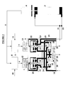
- Figure 1 is a scheme of a piston servo-actuation system including two single-stage, three-way servovalves.
- Figure 2 is a similar scheme to Figure 1, but including two-stage, three-way servovalves.
- Figure 3 is a similar scheme to Figure 1, but including single-stage, four-way servovalves.
- Figure 4 is a similar scheme to Figure 1, but including two-stage, four-way servovalves.
- the piston servo-actuation main system works with hydraulic fluid provided by a pump and consists of two servovalves 1, 2 which position a piston 3, which is mechanically linked to a transducer to measure its position 5 electrically, as a function of the electrical demands 6, 7, supplied by their dedicated feedback position control loops 8, 9 as a function of the piston position demands 10, 11 to their dedicated torquemotors of the servovalves 12, 13; the system being completed with two pressure select valves 14, 15, and the corresponding interconnecting servo circuits.
- the servovalves 1, 2 may be: a) single-stage, three-way (figure 1); b) two-stage, three-way (figure 2); c) single-stage, four-way (figure 3); d) two-stage, four-way (figure 4).
- the functional descriptions which follow are applicable not only to single-stage but also to two-stage servovalves. The use of one or the other type will depend upon the functional characteristics required. The use of three or four way servovalves will however modify both system configuration and some functional aspects of the system. The descriptions that follow will therefore distinguish one type from the other, also mentioning the differences between both.
- This type of system is designed for the actuation of a piston with either no external loads applied or negligible external loads applied compared to the hydraulic loads generated by the servovalves (friction loads, etc.).
- This system will be able to detect and self-compensate for any single failure of any feedback position control loop, any servovalve or leakage or seizure of the piston, as follows.
- the respective torquemotors 12, 13 of the two servovalves 1, 2 have identical electro-hydromechanical design characteristics and are controlled, respectively, by a control system with identical feedback position control loops of piston 3, i.e. loop 8 for servovalve 1 and loop 9 for servovalve 2, supplied with the same position demand 10, 11 and fed back both simultaneously with the same position signal 5 of piston 3 supplied by the position transducer 4, mechanically linked to piston 3.
- Both servovalves 1, 2 are fed with the same hydraulic supply circuit connected to the high pressure supply line, supply pressure 16, and to the low pressure line, return pressure 17, of the pump supply, which provides the hydraulic pressure and flow needed for an adequate control of servovalves 1, 2.
- Each servovalve is provided with a single control line: line 18 for servovalve 1 and line 19 for servovalve 2.
- control line in each servovalve will consist in controlling the position of piston 3 by means of connecting line 18 from the servovalve 1 to line 19 from the servovalve 2 to opposite sides.
- Control lines 18, 19 from servovalves 1, 2 will be placed in opposite sides relative to the actuation of the torquemotors 12, 13 (this may be accomplished by either opposite physical positioning of the control lines relative to the torquemotors or else by polarity inversion of the electrical circuit feeding the torquemotor windings).
- the aim of this configuration is the following: piston 3 is normally controlled in position as a function of the same electrical demand in 6, 7 coming from the feedback position control loops 8, 9 to their respective servovalves 1, 2, since the feedback loops 8, 9 are physically identical and are supplied with the same position 5 from the transducer 4, and the same position demand in 10, 11.
- the servovalves 1, 2 act together as if it was an only servovalve, as it retains the same hydraulic bridge configuration formed by: a) lines 16, 18, 17 controlled by restrictions 20, 21 in servovalve 1; b) lines 16, 19, 17 controlled by restrictions 22, 23 in servovalve 2. Furthermore, as the piston is, in normal conditions, not subjected to significant loads, the pressure in lines 18, 19 will be very similar.
- Lines 24, 25 are extensions of control lines 18, 19 from servovalves 1, 2 and will serve as a reference for checking system condition by the operation of the pressure select valves 14, 15. Pressure in lines 24, 25 will respectively be alike to those in lines 18, 19 and very similar, as mentioned above.
- the pressure select valves 14, 15 receive pressure from the working line 26 obtained with the supply pressure 16 and return pressure 17 by means of restrictions 27, 28.
- the aim of this line is reproducing the reference pressure in lines 24, 25 when both servovalves 1, 2 are operative. This may be accomplished as the hydraulic bridge created has not its control line loaded.
- the servovalves are operative, the sum of the flow number of the restrictions 20, 22 and the sum of the flow number of the restrictions 21, 23 in the servovalves are going to be respectively constant (servovalve design condition).
- the fixed restrictions 27, 28 should be assigned a value such that the pressure in line 26 is the same as that for the summed restrictions 20 + 22 and 21 + 23 in lines 24 and 25, i.e. their values squared should be kept at the same rate.
- the pressure select valves 14, 15 are identical in design and are configured in the following way: a) pressure select valve 14 receives pressure from the working line 26 on one side and pressure from the reference line 24 and spring load on the other; b) pressure select valve 15 receives pressure from the working line 26 and spring load on one side and pressure from the reference line 25 on the other.
- the signal of the state line 29 may be used as a criteria to initiate the control transfer sequence from this main servo-actuation system to a back-up servo-actuation system.
- This transfer must be accomplished by elements of the global servo-actuation system which are not the subject of this invention.
- the transfer may be: 1) partial, keeping piston 3 and position transducer 4 as part of the back-up servo-actuation system, i.e. disconnecting control lines 18, 19 from the piston 3 in points 31, 32 and connecting those points to the control lines of the back-up servo-actuation system; 2) total, where the back-up servo-actuation system has its own piston and position transducer. Should this be the case, the control transfer should be made between the outlet functions of both pistons. The type of transfer made will be greatly dependent upon on the reliability of the piston used. If the potential of this invention needs to be used to override e.g. possible piston seizures, the use of the type of transfer indicated in point 2) is recommended.
- This type of system is designed for the actuation of a piston subjected to any loading and will be able to detect and self-compensate for any single failure in the feedback position control loop or any servovalve.
- each servovalve 1, 2 is provided with two control lines; lines 18, 33 for servovalve 1 and lines 19, 34 for servovalve 2.
- the pressure in the reference line 35 formed by joining control lines 33, 34 will be a function of the same electrical demand in 6, 7 from the piston feedback position control loops 8, 9 to their dedicated servovalves 1, 2, since the feedback loops 8, 9 are physically identical and are provided with the same position 5 from the transducer 4 and the same position demand in 10, 11.
- the servovalves 1, 2 act together as if an only servovalve without load was used, as it has the same hydraulic bridge configuration formed by: a) lines 16, 33, 17 controlled by restrictions 36, 37 in servovalve 1; b) lines 16, 34, 17 controlled by restrictions 38, 39 in servovalve 2.
- the level of pressure in the reference line 35 will correspond to the design value of a servovalve operating without load.
- the pressure select valves 14, 15 are going to receive pressure from the working line 26 in the same fashion as in system A), though in this case, the aim of this line is reproducing the reference pressure in line 35 when both servovalves 1, 2 are operative.
- the sum of the flow number of the restrictions 36, 38 and the sum of the flow number of the restrictions 37, 39 in the servovalves are going to be respectively constant (servovalve design condition).
- the fixed restrictions 27, 28 should be assigned a value such that the pressure in line 26 is the same as that for the summed restrictions 36 + 38 and 37 + 39 in line 35, i.e. their values squared should be kept at the same rate.
- the pressure select valves 14, 15 are identical in design and are configured in the following way: a) pressure select valve 14 receives pressure from the working line 26 on one side and pressure from the reference line 35 and spring load on the other; b) pressure select valve 15 receives pressure from the working line 26 and spring load on one side and pressure from the reference line 35 on the other.
Landscapes
- Engineering & Computer Science (AREA)
- Physics & Mathematics (AREA)
- Fluid Mechanics (AREA)
- Mechanical Engineering (AREA)
- General Engineering & Computer Science (AREA)
- Chemical & Material Sciences (AREA)
- Analytical Chemistry (AREA)
- Fluid-Pressure Circuits (AREA)
- Servomotors (AREA)
Applications Claiming Priority (2)
| Application Number | Priority Date | Filing Date | Title |
|---|---|---|---|
| ES9801795 | 1998-08-24 | ||
| ES9801795A ES2156497B1 (es) | 1998-06-23 | 1998-08-24 | Mejoras en el objeto de la patente 9801320, relativa a "sistema principal de servo-actuacion de piston con deteccion hidromecanica de fallos autocontenida. |
Publications (3)
| Publication Number | Publication Date |
|---|---|
| EP0982503A2 true EP0982503A2 (fr) | 2000-03-01 |
| EP0982503A3 EP0982503A3 (fr) | 2002-05-02 |
| EP0982503B1 EP0982503B1 (fr) | 2005-09-14 |
Family
ID=8304966
Family Applications (1)
| Application Number | Title | Priority Date | Filing Date |
|---|---|---|---|
| EP99500152A Expired - Lifetime EP0982503B1 (fr) | 1998-08-24 | 1999-08-23 | Piston à servocommande avec détection hydromécanique autonome |
Country Status (4)
| Country | Link |
|---|---|
| US (1) | US6382076B1 (fr) |
| EP (1) | EP0982503B1 (fr) |
| CA (1) | CA2281066C (fr) |
| DE (1) | DE69927220T2 (fr) |
Cited By (2)
| Publication number | Priority date | Publication date | Assignee | Title |
|---|---|---|---|---|
| FR2981133A1 (fr) * | 2011-10-10 | 2013-04-12 | In Lhc | Procede de detection de defaillance d'une servovalve et servovalve faisant application. |
| CN119737350A (zh) * | 2024-12-30 | 2025-04-01 | 哈尔滨工业大学 | 液压伺服系统的油源供给系统 |
Families Citing this family (8)
| Publication number | Priority date | Publication date | Assignee | Title |
|---|---|---|---|---|
| US6637199B2 (en) * | 2002-01-28 | 2003-10-28 | Woodward Governor Co. | Pressure switching valve for multiple redundant electrohydraulic servo valve systems |
| DE102008041399A1 (de) * | 2008-08-20 | 2010-02-25 | Zf Friedrichshafen Ag | Verfahren zum Betreiben einer hydraulischen oder pneumatischen Steuerungseinrichtung eines automatisierten Schaltgetriebes |
| EP2711561B1 (fr) * | 2012-09-21 | 2019-08-28 | Danfoss Power Solutions Aps | Dispositif avec une soupape de commande électrohydraulique |
| CN104019082B (zh) * | 2013-02-28 | 2016-03-16 | In-Lhc公司 | 检测伺服阀故障的方法及应用该方法的伺服阀 |
| US9657756B2 (en) | 2014-08-14 | 2017-05-23 | Hamilton Sundstrand Corporation | Actuator system |
| CN107504015B (zh) * | 2017-10-10 | 2024-04-05 | 宁波创力液压机械制造有限公司 | 一种电缆拉力测试装置 |
| FI130631B (en) * | 2021-10-21 | 2023-12-19 | Ponsse Oyj | Control circuit for a harvester head |
| US20250044816A1 (en) * | 2023-07-31 | 2025-02-06 | Hamilton Sundstrand Corporation | Valve systems |
Family Cites Families (18)
| Publication number | Priority date | Publication date | Assignee | Title |
|---|---|---|---|---|
| US2995014A (en) * | 1960-04-26 | 1961-08-08 | Bell Aerospace Corp | Dual electro-hydraulic servo actuator system |
| GB1131854A (en) * | 1965-06-18 | 1968-10-30 | Elliott Brothers London Ltd | Improvements in and relating to the monitoring of control systems |
| US3738227A (en) * | 1969-08-18 | 1973-06-12 | Univ Illinois | Fluid positionable means and fluid control means therefor |
| CH509535A (de) * | 1970-05-06 | 1971-06-30 | Technomatic Ag | Sicherheitsventil für druckmittelbetriebene Vorrichtungen |
| US3714868A (en) * | 1970-09-23 | 1973-02-06 | Marotta Scientific Controls | Valve system for proportional flow control for fluid-operated motor |
| GB1369441A (en) * | 1970-12-11 | 1974-10-09 | Dowty Boulton Paul Ltd | Electro-hydraulic control system |
| DE2654366C2 (de) * | 1976-12-01 | 1984-08-23 | Gebr. Claas, 4834 Harsewinkel | Hydroventileinrichtung |
| DE3017080C2 (de) * | 1980-05-03 | 1985-11-28 | Deutsche Forschungs- und Versuchsanstalt für Luft- und Raumfahrt e.V., 5000 Köln | Elektrohydraulischer Stellantrieb |
| DE3563774D1 (en) * | 1984-08-11 | 1988-08-18 | Lucas Ind Plc | Fluid powered actuator system |
| US4840111A (en) * | 1986-01-31 | 1989-06-20 | Moog Inc. | Energy-conserving regenerative-flow valves for hydraulic servomotors |
| USH249H (en) * | 1986-10-07 | 1987-04-07 | The United States Of America As Represented By The Secretary Of The Army | Dual rate actuator |
| JPS63303247A (ja) * | 1987-05-30 | 1988-12-09 | Diesel Kiki Co Ltd | 自動変速装置 |
| CH675752A5 (fr) * | 1988-10-25 | 1990-10-31 | Sulzer Ag | |
| DE3901475C2 (de) * | 1989-01-19 | 1994-07-14 | Danfoss As | Fluidgesteuerte Servoanordnung |
| JP2846510B2 (ja) * | 1991-06-24 | 1999-01-13 | 本田技研工業株式会社 | 油圧サーボユニットの作動制御装置 |
| DE4340283A1 (de) * | 1993-11-26 | 1995-06-01 | Claas Ohg | Hydraulisches Steuerventil |
| US5868059A (en) * | 1997-05-28 | 1999-02-09 | Caterpillar Inc. | Electrohydraulic valve arrangement |
| DE19737005A1 (de) * | 1997-08-26 | 1999-03-04 | Claas Selbstfahr Erntemasch | Vorrichtung zur Steuerung eines doppelt wirkenden Lenkzylinders |
-
1999
- 1999-08-23 DE DE69927220T patent/DE69927220T2/de not_active Expired - Lifetime
- 1999-08-23 US US09/379,241 patent/US6382076B1/en not_active Expired - Lifetime
- 1999-08-23 EP EP99500152A patent/EP0982503B1/fr not_active Expired - Lifetime
- 1999-08-24 CA CA002281066A patent/CA2281066C/fr not_active Expired - Fee Related
Non-Patent Citations (1)
| Title |
|---|
| None |
Cited By (5)
| Publication number | Priority date | Publication date | Assignee | Title |
|---|---|---|---|---|
| FR2981133A1 (fr) * | 2011-10-10 | 2013-04-12 | In Lhc | Procede de detection de defaillance d'une servovalve et servovalve faisant application. |
| EP2581609A1 (fr) * | 2011-10-10 | 2013-04-17 | In-Lhc | Procédé de détection de défaillance d'une servovalve et servovalve faisant application |
| JP2013083354A (ja) * | 2011-10-10 | 2013-05-09 | In-Lhc | サーボバルブの異常を検出する方法とその方法を適用したサーボバルブ |
| US9897116B2 (en) | 2011-10-10 | 2018-02-20 | In-Lhc | Method of detecting failure of a servo-valve, and a servo-valve applying the method |
| CN119737350A (zh) * | 2024-12-30 | 2025-04-01 | 哈尔滨工业大学 | 液压伺服系统的油源供给系统 |
Also Published As
| Publication number | Publication date |
|---|---|
| DE69927220D1 (de) | 2005-10-20 |
| EP0982503B1 (fr) | 2005-09-14 |
| EP0982503A3 (fr) | 2002-05-02 |
| US6382076B1 (en) | 2002-05-07 |
| CA2281066C (fr) | 2008-02-12 |
| CA2281066A1 (fr) | 2000-02-24 |
| DE69927220T2 (de) | 2006-07-13 |
Similar Documents
| Publication | Publication Date | Title |
|---|---|---|
| CA2281066C (fr) | Systeme de conduites d'eau a servomoteurs a piston avec detection autonome hydromecanique de pannes | |
| US4887214A (en) | Flight control system employing two dual controllers operating a dual actuator | |
| EP0573191A1 (fr) | Vannes hydrauliques à deux étages | |
| US6164068A (en) | Variable pressure hydraulic systems | |
| US7200993B2 (en) | Electro-hydraulic steering control system | |
| EP0515692A4 (en) | Hydraulic circuit system | |
| JPH01501726A (ja) | 負荷補償方向制御弁の負荷検知回路 | |
| CA1105391A (fr) | Detecteur de panne ehv a redonnance | |
| US3991571A (en) | Fluid system of a work vehicle having fluid combining means and signal combining means | |
| US6560961B2 (en) | Steering system with ability to stop steering wheel rotation | |
| US3279323A (en) | Electrohydraulic actuator | |
| JP3592377B2 (ja) | 液圧式の安全回路 | |
| EP0110501B1 (fr) | Système d'actionnement à commande redondante d'une valve concentrique entraînée directement | |
| US5143119A (en) | Drive for a feed valve | |
| US8096321B2 (en) | Redundant electrohydraulic valve system | |
| EP0136005B1 (fr) | Mécanisme de commande ou d'amortissement d'un servo-actionneur | |
| WO1994010457A1 (fr) | Vanne de regulation de pression destinee a un actuateur hydraulique | |
| US4447769A (en) | Redundant actuation system | |
| US20080078456A1 (en) | Hydrostatic variable unit with a servo system and a valve unit controlling the servo system | |
| US4155288A (en) | Control system for a fluid pressure operated actuator arrangement | |
| US4194361A (en) | Electro-mechanical control system for hydraulic displacement pumps, such as swash plate or eccenter pumps | |
| JPH06123301A (ja) | 建設機械の油圧制御装置 | |
| CN114704508A (zh) | 一种用于电液伺服六自由度并联机器人的多裕度液压系统 | |
| US4436018A (en) | Multiple loop control system | |
| EP0190467B1 (fr) | Dispositif de commande de vérin pour le rendre passif en cas de défaillance |
Legal Events
| Date | Code | Title | Description |
|---|---|---|---|
| PUAI | Public reference made under article 153(3) epc to a published international application that has entered the european phase |
Free format text: ORIGINAL CODE: 0009012 |
|
| AK | Designated contracting states |
Kind code of ref document: A2 Designated state(s): AT BE CH CY DE DK ES FI FR GB GR IE IT LI LU MC NL PT SE Kind code of ref document: A2 Designated state(s): DE FR GB IT SE |
|
| AX | Request for extension of the european patent |
Free format text: AL;LT;LV;MK;RO;SI |
|
| PUAL | Search report despatched |
Free format text: ORIGINAL CODE: 0009013 |
|
| AK | Designated contracting states |
Kind code of ref document: A3 Designated state(s): AT BE CH CY DE DK ES FI FR GB GR IE IT LI LU MC NL PT SE |
|
| AX | Request for extension of the european patent |
Free format text: AL;LT;LV;MK;RO;SI |
|
| 17P | Request for examination filed |
Effective date: 20021017 |
|
| AKX | Designation fees paid |
Free format text: DE FR GB IT SE |
|
| 17Q | First examination report despatched |
Effective date: 20030602 |
|
| GRAP | Despatch of communication of intention to grant a patent |
Free format text: ORIGINAL CODE: EPIDOSNIGR1 |
|
| GRAS | Grant fee paid |
Free format text: ORIGINAL CODE: EPIDOSNIGR3 |
|
| GRAA | (expected) grant |
Free format text: ORIGINAL CODE: 0009210 |
|
| AK | Designated contracting states |
Kind code of ref document: B1 Designated state(s): DE FR GB IT SE |
|
| REG | Reference to a national code |
Ref country code: GB Ref legal event code: FG4D |
|
| REF | Corresponds to: |
Ref document number: 69927220 Country of ref document: DE Date of ref document: 20051020 Kind code of ref document: P |
|
| REG | Reference to a national code |
Ref country code: SE Ref legal event code: TRGR |
|
| ET | Fr: translation filed | ||
| PLBE | No opposition filed within time limit |
Free format text: ORIGINAL CODE: 0009261 |
|
| STAA | Information on the status of an ep patent application or granted ep patent |
Free format text: STATUS: NO OPPOSITION FILED WITHIN TIME LIMIT |
|
| 26N | No opposition filed |
Effective date: 20060615 |
|
| REG | Reference to a national code |
Ref country code: FR Ref legal event code: PLFP Year of fee payment: 18 |
|
| PGFP | Annual fee paid to national office [announced via postgrant information from national office to epo] |
Ref country code: DE Payment date: 20160816 Year of fee payment: 18 Ref country code: GB Payment date: 20160817 Year of fee payment: 18 Ref country code: IT Payment date: 20160802 Year of fee payment: 18 |
|
| PGFP | Annual fee paid to national office [announced via postgrant information from national office to epo] |
Ref country code: FR Payment date: 20160712 Year of fee payment: 18 Ref country code: SE Payment date: 20160811 Year of fee payment: 18 |
|
| REG | Reference to a national code |
Ref country code: DE Ref legal event code: R119 Ref document number: 69927220 Country of ref document: DE |
|
| GBPC | Gb: european patent ceased through non-payment of renewal fee |
Effective date: 20170823 |
|
| PG25 | Lapsed in a contracting state [announced via postgrant information from national office to epo] |
Ref country code: SE Free format text: LAPSE BECAUSE OF NON-PAYMENT OF DUE FEES Effective date: 20170824 |
|
| REG | Reference to a national code |
Ref country code: FR Ref legal event code: ST Effective date: 20180430 |
|
| PG25 | Lapsed in a contracting state [announced via postgrant information from national office to epo] |
Ref country code: GB Free format text: LAPSE BECAUSE OF NON-PAYMENT OF DUE FEES Effective date: 20170823 Ref country code: DE Free format text: LAPSE BECAUSE OF NON-PAYMENT OF DUE FEES Effective date: 20180301 |
|
| PG25 | Lapsed in a contracting state [announced via postgrant information from national office to epo] |
Ref country code: FR Free format text: LAPSE BECAUSE OF NON-PAYMENT OF DUE FEES Effective date: 20170831 Ref country code: IT Free format text: LAPSE BECAUSE OF NON-PAYMENT OF DUE FEES Effective date: 20170823 |