EP2581609A1 - Procédé de détection de défaillance d'une servovalve et servovalve faisant application - Google Patents
Procédé de détection de défaillance d'une servovalve et servovalve faisant application Download PDFInfo
- Publication number
- EP2581609A1 EP2581609A1 EP20120187609 EP12187609A EP2581609A1 EP 2581609 A1 EP2581609 A1 EP 2581609A1 EP 20120187609 EP20120187609 EP 20120187609 EP 12187609 A EP12187609 A EP 12187609A EP 2581609 A1 EP2581609 A1 EP 2581609A1
- Authority
- EP
- European Patent Office
- Prior art keywords
- servovalve
- motor
- movable
- rotor
- power distribution
- Prior art date
- Legal status (The legal status is an assumption and is not a legal conclusion. Google has not performed a legal analysis and makes no representation as to the accuracy of the status listed.)
- Granted
Links
Images
Classifications
-
- F—MECHANICAL ENGINEERING; LIGHTING; HEATING; WEAPONS; BLASTING
- F15—FLUID-PRESSURE ACTUATORS; HYDRAULICS OR PNEUMATICS IN GENERAL
- F15B—SYSTEMS ACTING BY MEANS OF FLUIDS IN GENERAL; FLUID-PRESSURE ACTUATORS, e.g. SERVOMOTORS; DETAILS OF FLUID-PRESSURE SYSTEMS, NOT OTHERWISE PROVIDED FOR
- F15B19/00—Testing; Calibrating; Fault detection or monitoring; Simulation or modelling of fluid-pressure systems or apparatus not otherwise provided for
- F15B19/005—Fault detection or monitoring
-
- F—MECHANICAL ENGINEERING; LIGHTING; HEATING; WEAPONS; BLASTING
- F15—FLUID-PRESSURE ACTUATORS; HYDRAULICS OR PNEUMATICS IN GENERAL
- F15B—SYSTEMS ACTING BY MEANS OF FLUIDS IN GENERAL; FLUID-PRESSURE ACTUATORS, e.g. SERVOMOTORS; DETAILS OF FLUID-PRESSURE SYSTEMS, NOT OTHERWISE PROVIDED FOR
- F15B13/00—Details of servomotor systems ; Valves for servomotor systems
- F15B13/02—Fluid distribution or supply devices characterised by their adaptation to the control of servomotors
- F15B13/04—Fluid distribution or supply devices characterised by their adaptation to the control of servomotors for use with a single servomotor
- F15B13/042—Fluid distribution or supply devices characterised by their adaptation to the control of servomotors for use with a single servomotor operated by fluid pressure
- F15B13/043—Fluid distribution or supply devices characterised by their adaptation to the control of servomotors for use with a single servomotor operated by fluid pressure with electrically-controlled pilot valves
- F15B13/0436—Fluid distribution or supply devices characterised by their adaptation to the control of servomotors for use with a single servomotor operated by fluid pressure with electrically-controlled pilot valves the pilot valves being of the steerable jet type
-
- H—ELECTRICITY
- H02—GENERATION; CONVERSION OR DISTRIBUTION OF ELECTRIC POWER
- H02K—DYNAMO-ELECTRIC MACHINES
- H02K11/00—Structural association of dynamo-electric machines with electric components or with devices for shielding, monitoring or protection
- H02K11/20—Structural association of dynamo-electric machines with electric components or with devices for shielding, monitoring or protection for measuring, monitoring, testing, protecting or switching
-
- H—ELECTRICITY
- H02—GENERATION; CONVERSION OR DISTRIBUTION OF ELECTRIC POWER
- H02K—DYNAMO-ELECTRIC MACHINES
- H02K26/00—Machines adapted to function as torque motors, i.e. to exert a torque when stalled
-
- Y—GENERAL TAGGING OF NEW TECHNOLOGICAL DEVELOPMENTS; GENERAL TAGGING OF CROSS-SECTIONAL TECHNOLOGIES SPANNING OVER SEVERAL SECTIONS OF THE IPC; TECHNICAL SUBJECTS COVERED BY FORMER USPC CROSS-REFERENCE ART COLLECTIONS [XRACs] AND DIGESTS
- Y10—TECHNICAL SUBJECTS COVERED BY FORMER USPC
- Y10T—TECHNICAL SUBJECTS COVERED BY FORMER US CLASSIFICATION
- Y10T137/00—Fluid handling
- Y10T137/0318—Processes
- Y10T137/0396—Involving pressure control
-
- Y—GENERAL TAGGING OF NEW TECHNOLOGICAL DEVELOPMENTS; GENERAL TAGGING OF CROSS-SECTIONAL TECHNOLOGIES SPANNING OVER SEVERAL SECTIONS OF THE IPC; TECHNICAL SUBJECTS COVERED BY FORMER USPC CROSS-REFERENCE ART COLLECTIONS [XRACs] AND DIGESTS
- Y10—TECHNICAL SUBJECTS COVERED BY FORMER USPC
- Y10T—TECHNICAL SUBJECTS COVERED BY FORMER US CLASSIFICATION
- Y10T137/00—Fluid handling
- Y10T137/2278—Pressure modulating relays or followers
-
- Y—GENERAL TAGGING OF NEW TECHNOLOGICAL DEVELOPMENTS; GENERAL TAGGING OF CROSS-SECTIONAL TECHNOLOGIES SPANNING OVER SEVERAL SECTIONS OF THE IPC; TECHNICAL SUBJECTS COVERED BY FORMER USPC CROSS-REFERENCE ART COLLECTIONS [XRACs] AND DIGESTS
- Y10—TECHNICAL SUBJECTS COVERED BY FORMER USPC
- Y10T—TECHNICAL SUBJECTS COVERED BY FORMER US CLASSIFICATION
- Y10T137/00—Fluid handling
- Y10T137/8158—With indicator, register, recorder, alarm or inspection means
- Y10T137/8225—Position or extent of motion indicator
- Y10T137/8242—Electrical
-
- Y—GENERAL TAGGING OF NEW TECHNOLOGICAL DEVELOPMENTS; GENERAL TAGGING OF CROSS-SECTIONAL TECHNOLOGIES SPANNING OVER SEVERAL SECTIONS OF THE IPC; TECHNICAL SUBJECTS COVERED BY FORMER USPC CROSS-REFERENCE ART COLLECTIONS [XRACs] AND DIGESTS
- Y10—TECHNICAL SUBJECTS COVERED BY FORMER USPC
- Y10T—TECHNICAL SUBJECTS COVERED BY FORMER US CLASSIFICATION
- Y10T137/00—Fluid handling
- Y10T137/8158—With indicator, register, recorder, alarm or inspection means
- Y10T137/8225—Position or extent of motion indicator
- Y10T137/8275—Indicator element rigidly carried by the movable element whose position is indicated
-
- Y—GENERAL TAGGING OF NEW TECHNOLOGICAL DEVELOPMENTS; GENERAL TAGGING OF CROSS-SECTIONAL TECHNOLOGIES SPANNING OVER SEVERAL SECTIONS OF THE IPC; TECHNICAL SUBJECTS COVERED BY FORMER USPC CROSS-REFERENCE ART COLLECTIONS [XRACs] AND DIGESTS
- Y10—TECHNICAL SUBJECTS COVERED BY FORMER USPC
- Y10T—TECHNICAL SUBJECTS COVERED BY FORMER US CLASSIFICATION
- Y10T137/00—Fluid handling
- Y10T137/8593—Systems
- Y10T137/86493—Multi-way valve unit
- Y10T137/86574—Supply and exhaust
- Y10T137/86582—Pilot-actuated
- Y10T137/8659—Variable orifice-type modulator
- Y10T137/86598—Opposed orifices; interposed modulator
Definitions
- the present invention relates to a method and a device for detecting a failure of a two-stage flow-rate servovalve, the movable power distribution member of which is connected to the rotor of the torque motor of the control stage by a mechanical return.
- the invention also relates to a servovalve comprising such a device.
- a conventional servovalve is constituted by an oscillating or deflected jet type or paddle type piloting stage controlling a movable power distribution member of the power stage.
- the function of the power stage is to deliver a pressure or a flow proportional to an instruction transmitted to the control stage.
- the relative position of the hydraulic transmitter (nozzle or ejector) and the hydraulic receiver (pallet, deflector or fixed receiver) of the control stage generates pressure differentials which are used to finely move the movable member. power distribution of the power stage of the servovalve.
- the position of the transmitter or the hydraulic receiver is controlled by a torque motor which moves one of the hydraulic elements of the control stage (the pallet for the servovalves with nozzles and pallet, the ejector for the servovalves with mobile ejector and deflector for fixed ejector servovalves) facing each other.
- a computer sends an instruction in the form of an electric current to the torque motor.
- This instruction causes an angular movement of the rotor of the torque motor relative to the stator, which, by modifying the relative position of the transmitter and the hydraulic receiver, causes a pressure differential on the movable power distribution member of the stage power. This then moves by a value substantially proportional to the electrical instruction received by the torque motor.
- Move the mobile power distribution member then communicates a set of drilled channels and lights whose arrangement allows to deliver a pressure or a flow, depending on the displacement of said power distribution member.
- the computer sends the shutdown command, the servovalve then stops the pressure delivery or debit. Control loops between the movement of the cylinder and the instruction of the servovalve are generally established via the computer.
- These servovalves usually comprise a mechanical connection between the rotor of the torque motor and the mobile power distribution member, called for example "feedback rod". It is generally located in the middle of the movable element and is also integral with the pallet or the ejector.
- Such servovalves are widely used in aeronautics, particularly for flight controls or wheel orientation.
- the onboard computer emits, upon request of the pilot, an instruction to the torque motor in order to generate a pressure or a flow rate adapted to achieve the desired movement of a hydraulic element.
- This calculator also receives information enabling it to verify that the desired movement has correctly location.
- the boarding of a servocontrol is defined as a defective state of the controlled equipment, such as a cylinder, which is positioned rapidly and abruptly in one of its extreme states. For example, for a cylinder, servocontrol boarding results in a quick passage of the rod of the cylinder to the state "stem completely out” or "rod completely retracted".
- the servovalve of this servo-control loop is also in a state of failure, among others one of the cases a) to d) above, in which it provides a flow or an outlet pressure different from that commanded by incorrect position of the dispensing spool of the power unit ".
- the measurement of a positional deviation of the movable power distribution member between the position controlled by the computer and its actual position indicates a malfunction of the servovalve.
- An object of the invention is to provide a simple method of failure detection of a two-stage servovalve with mechanical feedback.
- a method for detecting the failure of a servovalve comprising a power stage with a mobile power distribution member and a driving stage comprising a torque motor, said torque motor comprising a stator and a rotor of which the angular position is controlled in order to move in a controlled manner the movable power distribution member, said movable power distribution member being connected to the rotor of the torque motor by a mechanical return, said method comprising according to the invention the detection of a coming into abutment of the rotor of the torque motor and the generation of a malfunction signal in response to this detection.
- the method is based on the detection of a discrete state: coming into abutment of the rotor.
- This type of state is detectable by simple means such as dry contacts or non-contact sensors (magnetic type for example).
- the choice of the detection means will depend on the nature of the detection circuit that is to be used in particular with respect to its ability to be disturbed by its environment or processing facilities by the computer generated signal. The simplicity of these means can also have the effect of improving the reliability, economy and mass of the device. It is possible to equip an existing servovalve, for extra cost and low overweight, with a particularly robust and reliable device that can generate a clear and fast malfunction signal.
- the invention also comprises a servovalve provided with means for implementing such a method.
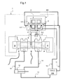
- the figure 1 is a block diagram of a servovalve generally designated 1. This may be integrated in the control circuit of a hydraulic equipment such as an aircraft wing flap control cylinder 12.
- the servovalve comprises a designated torque motor MC
- the servovalve 1 comprises a control stage and a power stage.
- the driving stage comprises a torque motor MC whose movement is controlled by a computer 100 which transmits its instructions to the torque motor MC via an instruction channel 10.
- the power stage is connected to a hydraulic power supply P, a port R and two outputs C1 and C2.
- the outputs C1 and C2 feed the two chambers of a double-acting cylinder 12 through the lines 14.
- the computer 100 receives information from the torque motor by a monitoring channel 11 as well as information on the position of the jack via the information channel 13.
- the rotor 3 is integral with a fluid ejector 4 which faces a fixed receiver 5.
- the ejector 4 selectively orients a hydraulic fluid according to the movement of the rotor 3.
- a mechanical feedback in the form of a feedback rod 6 mechanically connects the movable power distribution member -the drawer 7- to the column 3.2.
- Interference detectors here in the form of switches NO 2.2, are arranged near the magnetic stops 2.1 and arranged to be actuated by the end of the magnetic paddle 3.1 when the rotor 3 abuts. They communicate with the computer 100 by the operation monitoring channel 11.
- the fixed receiver 5 has 2 channels 8, schematically shown, which open into the chambers 9 located on either side of the drawer. A movement of the rotor 3 moves the ejector 4 relative to the deflector 5. Two different flows are then directed via the channels 8 in the chambers 9 located on either side of the slide 7. These flows create a differential pressure in the chambers 9 which causes the translation of the slide 7 which delivers to the cylinder 12, via the lines 14, a servovalve output flow 1 substantially proportional to the control current applied to the input of the torque motor MC.
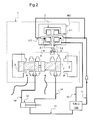
- the figure 2 is a representation of the servovalve 1 in the case of an anomaly, here the rupture of the feedback rod 6.
- the drawer 7 will immediately abut at the bottom of one or the other of the chambers 9, causing a boarding of the servo.
- a high flow rate is then delivered by the servovalve 1 to the cylinder 12 via the lines 14.
- the computer 0, informed of the movement of the cylinder 12 by the information channel 13 sends a corrective instruction to the servovalve by the instruction channel 10
- This corrective instruction is maintained as long as the movement of the cylinder 12 has not been in conformity.
- the magnetic paddle 3.1 of the rotor 3 comes on one of the magnetic stops 2.1 and closes one of the switches 2.2.
- the closure of this circuit generates a malfunction signal on the operation monitoring channel 11. It may be useful to add a timer or a filter to the detection of the closing of one of the switches 2.2 since strong rate calls can generate brief abutments of the rotor 3.
- the high dynamics of the first stage makes the speed of detection by the device of the invention is of the same order as that of a system comprising a LVDT type sensor on the servovalve drawer.
- the malfunction signal can trigger an alert to the driver or be directly processed by the computer that can decide to apply a security procedure of disabling the faulty servovalve and activate any redundant hardware.
Landscapes
- Engineering & Computer Science (AREA)
- Physics & Mathematics (AREA)
- Fluid Mechanics (AREA)
- Mechanical Engineering (AREA)
- General Engineering & Computer Science (AREA)
- Power Engineering (AREA)
- Microelectronics & Electronic Packaging (AREA)
- Fluid-Pressure Circuits (AREA)
- Indication Of The Valve Opening Or Closing Status (AREA)
- Servomotors (AREA)
- Stopping Of Electric Motors (AREA)
- Control Of Electric Motors In General (AREA)
- Electrically Driven Valve-Operating Means (AREA)
- Control Of Position Or Direction (AREA)
Abstract
Description
- La présente invention concerne un procédé et un dispositif de détection de défaillance d'une servovalve de débit à deux étages dont l'organe mobile de distribution de puissance est relié au rotor du moteur couple de l'étage de pilotage par un retour mécanique. L'invention a également pour objet une servovalve comportant un tel dispositif.
- Une servovalve classique est constituée d'un étage de pilotage de type à jet oscillant ou dévié ou de type à buses avec palette pilotant un organe mobile de distribution de puissance de l'étage de puissance. L'étage de puissance a pour fonction de délivrer une pression ou un débit proportionnels à une instruction transmise à l'étage de pilotage.
- Dans ces servovalves, la position relative de l'émetteur hydraulique (buse ou éjecteur) et du récepteur hydraulique (palette, déflecteur ou récepteur fixe) de l'étage de pilotage génère des différentiels de pression qui sont exploités pour déplacer finement l'organe mobile de distribution de puissance de l'étage de puissance de la servovalve. Généralement, la position de l'émetteur ou du récepteur hydraulique est pilotée par un moteur couple qui déplace l'un des éléments hydrauliques de l'étage de pilotage (la palette pour les servovalves à buses et palette, l'éjecteur pour les servovalves à éjecteur mobile et le déflecteur pour les servovalves à éjecteur fixe) en regard de l'autre. En réponse à une demande d'un utilisateur, un calculateur envoie une instruction sous forme d'un courant électrique au moteur couple. Cette instruction entraîne un mouvement angulaire du rotor du moteur couple par rapport au stator, qui, en modifiant la position relative de l'émetteur et du récepteur hydraulique, entraîne un différentiel de pression sur l'organe mobile de distribution de puissance de l'étage de puissance. Celui-ci se déplace alors d'une valeur sensiblement proportionnelle à l'instruction électrique reçue par le moteur couple. Le déplacement de l'organe mobile de distribution de puissance met alors en communication un ensemble de canaux forés et de lumières dont l'agencement permet de délivrer une pression ou un débit, en fonction du déplacement dudit organe de distribution de puissance. Lorsque l'effet souhaité (généralement le positionnement d'un élément mû par un vérin relié à l'étage de puissance d'une servovalve) est obtenu, le calculateur envoie l'instruction d'arrêt, la servovalve arrête alors la délivrance de pression ou de débit. Des boucles d'asservissement entre le mouvement du vérin et l'instruction de la servovalve sont généralement établies via le calculateur.
- Ces servovalves comprennent usuellement une liaison mécanique entre le rotor du moteur couple et l'organe mobile de distribution de puissance, appelée par exemple « tige de rétroaction ». Elle est généralement implantée au milieu de l'élément mobile et est également solidaire de la palette ou l'éjecteur.
- De telles servovalves sont largement utilisées dans l'aéronautique, notamment pour les commandes de vol ou l'orientation des roues.
- La fonction de ces organes étant critique, il est important pour la sûreté des aéroplanes de pouvoir surveiller la conformité du fonctionnement des servovalves et ainsi alerter le calculateur de bord en cas de défaut avant même que le fonctionnement défectueux de la servovalve puisse causer un dysfonctionnement perceptible du matériel commandé. Le pilote ou le système peut alors déconnecter l'équipement identifié comme défectueux et activer un éventuel équipement redondant.
- Classiquement, le calculateur de bord émet, suite à demande du pilote, une instruction vers le moteur couple dans le but de générer une pression ou un débit adaptés à la réalisation du mouvement souhaité d'un élément hydraulique. Ce calculateur reçoit également des informations lui permettant de vérifier que le mouvement souhaité a correctement lieu.
- Les défauts pouvant affecter une servovalve impactent tous la position de l'organe mobile de distribution de puissance. On peut notamment citer les cas de défaillance suivants :
- a) Tiroir en position fin de course créant un embarquement rapide de la servocommande : rupture de tige de rétroaction, extrusion de certains joints de fourrure, ...
- b) Tiroir bloqué créant un embarquement plus ou moins brusque selon le débit sur lequel est bloqué le tiroir : copeau coincé entre la fourrure et le tiroir
- c) Rupture d'alimentation hydraulique de l'étage de pilotage : fissure dans les pièces de structure, colmatage de l'alimentation hydraulique du premier étage.
- d) Rupture d'alimentation électrique : rupture des 2 bobines, rupture des fils d'alimentation. La détection de ce type de panne est usuellement dévolue au dispositif de contrôle du calculateur.
- L'embarquement d'une servocommande se définit comme un état défectueux du matériel commandé, tel un vérin, qui se positionne rapidement et brusquement dans un de ses états extrêmes. Par exemple, pour un vérin, l'embarquement de servocommande se traduit par un passage rapide de la tige du vérin jusqu'à l'état « tige complètement sortie » ou « tige complètement rentrée ». La servovalve de cette boucle de servocommande est également dans un état de défaillance, entre autres l'un des cas a) à d) ci-dessus, dans laquelle elle fournit un débit ou une pression de sortie différente de celle commandée du fait d'une position incorrecte du tiroir de distribution de l'organe de puissance ».
- La mesure d'un écart de position de l'organe mobile de distribution de puissance entre la position commandée par le calculateur et sa position effective traduit un dysfonctionnement de la servovalve.
- Actuellement, la détermination de la position de l'organe mobile de distribution de puissance est réalisée par un capteur de déplacement linéaire passif de type LVDT. Ce type de capteur nécessite un module électronique, appelé conditionneur, pour pouvoir fonctionner. Ces capteurs présentent l'avantage d'être de constitution simple, de pouvoir fonctionner dans des environnements extrêmement contraignants et d'avoir une bonne résolution. Cependant, l'intégration de ce type de capteur à la servovalve pose les problèmes suivants :
- l'encombrement de la servovalve se voit augmenté de 10 à 50% selon les modèles ;
- la masse de la servovalve se voit augmentée de 5 à 20%. Cet effet est particulièrement dommageable pour les applications aéronautiques où l'allégement des équipements est la règle ;
- le coût d'une servovalve équipée est de 5 à 20% supérieur à celui d'une servovalve non équipée ;
- le temps moyen entre pannes (Mean Time Between Failure) est augmenté de 10 à 20% ;
- la nécessité d'un conditionneur traitant le signal du capteur pénalise supplémentairement les aspects d'encombrement, de masse, de coût et de fiabilité.
- Un but de l'invention est de proposer un procédé simple de détection de défaillance d'une servovalve à deux étages à rétroaction mécanique.
- A cet effet, on propose, un procédé de détection de défaillance d'une servovalve comportant un étage de puissance avec un organe mobile de distribution de puissance et un étage de pilotage comportant un moteur couple, ce moteur couple comprenant un stator et un rotor dont la position angulaire est commandée afin de déplacer de façon contrôlée l'organe mobile de distribution de puissance, ledit organe mobile de distribution de puissance étant relié au rotor du moteur couple par un retour mécanique, ledit procédé comprenant selon l'invention la détection d'une venue en butée du rotor du moteur couple et la génération d'un signal de dysfonctionnement en réponse à cette détection.
- Le procédé est basé sur la détection d'un état discret : venue en butée du rotor. Ce type d'état est détectable par des moyens simples tels que des contacts secs ou des capteurs sans contact (de type magnétique par exemple). Le choix du moyen de détection dépendra de la nature du circuit de détection que l'on souhaite mettre en oeuvre notamment en regard de sa capacité à être perturbé par son environnement ou des facilités de traitement par le calculateur du signal généré. La simplicité de ces moyens peut avoir également pour effet d'améliorer la fiabilité, l'économie et la masse du dispositif. Il est possible d'équiper une servovalve existante, pour un surcoût et un surpoids faible, d'un dispositif particulièrement robuste et fiable pouvant générer un signal de dysfonctionnement clair et rapide.
- Les inventeurs se sont en effet aperçus qu'un défaut de fonctionnement de la servovalve entraînait le plus souvent une venue en butée du rotor du moteur couple.
- Lors d'une défaillance de la servovalve, le calculateur de bord émet une instruction corrective (augmentation/réduction/arrêt de l'alimentation hydraulique) vers la servovalve. Celle-ci se traduit par l'application d'un couple électromagnétique sur le rotor aussi longtemps que le mouvement souhaité de l'élément hydraulique n'a pas été exécutée. Ainsi, en cas de défaillance de la servovalve, un couple constant étant appliqué sur le rotor, celui-ci vient sur l'une de ses butées, la souplesse des éléments liés au rotor autorisant ce mouvement.
- L'invention comprend également une servovalve pourvue de moyens pour mettre en oeuvre un tel procédé.
- D'autres caractéristiques et avantages de l'invention ressortiront à la lecture de la description qui suit de modes de réalisation particuliers non limitatifs de l'invention.
- Il sera fait référence aux dessins annexés, parmi lesquels :
- la
figure 1 est une vue schématique d'une servovalve dans une configuration sans dysfonctionnement - la
figure 2 est une vue schématique d'une servovalve dans une configuration avec dysfonctionnement - La
figure 1 est un schéma fonctionnel d'une servovalve généralement désignée 1. Celle-ci peut être intégrée au circuit de commande d'un équipement hydraulique comme un vérin de commande de volet d'aile d'avion 12. La servovalve comprend un moteur couple désigné MC - La servovalve 1 comprend un étage de pilotage et un étage de puissance. L'étage de pilotage comprend un moteur couple MC dont le mouvement est commandé par un calculateur 100 qui transmet ses instructions au moteur couple MC via un canal d'instructions 10. L'étage de puissance est relié à une alimentation hydraulique P, un port de retour R et deux sorties C1 et C2 .Les sorties C1 et C2 alimentent les 2 chambres d'un vérin double effet 12 par les conduites 14. Le calculateur 100 reçoit des informations en provenance du moteur couple par un canal de surveillance de fonctionnement 11 ainsi que des informations sur la position du vérin par le canal d'information 13.
- Le moteur couple MC comprend un stator 2 et un rotor 3. Le stator 2 est une cage entourant le rotor 3 et disposant de butées magnétiques 2.1 destinées à accueillir le rotor dans ses positions extrêmes. Le rotor 3 comprend deux éléments principaux:
- une palette magnétique 3.1 sollicitée par le champ magnétique développé par le stator et mobile par rapport au corps de la servovalve 1
- une colonne 3.2 s'étendant en saillie du stator et pénétrant à l'intérieur du corps de la servovalve.
- Le rotor 3 est solidaire d'un éjecteur à fluide 4 qui fait face à un receveur fixe 5. L'éjecteur 4 oriente sélectivement un fluide hydraulique en fonction du mouvement du rotor 3. Un retour mécanique sous la forme d'une tige de rétroaction 6 relie mécaniquement l'organe mobile de distribution de puissance -le tiroir 7- à la colonne 3.2.
- Des détecteurs de venue en butée, ici sous la forme d'interrupteurs NO 2.2, sont disposés à proximité des butées magnétiques 2.1 et agencés de manière à être actionnés par l'extrémité de la palette magnétique 3.1 lorsque le rotor 3 vient en butée. Ils communiquent avec le calculateur 100 par le canal surveillance de fonctionnement 11. Le receveur fixe 5 dispose de 2 canaux 8, schématiquement représentés, qui débouchent dans les chambres 9 situées de part et d'autre du tiroir. Un mouvement du rotor 3 déplace l'éjecteur 4 relativement au déflecteur 5. Deux flux différents sont alors dirigés via les canaux 8 dans les chambres 9 situées de part et d'autre du tiroir 7. Ces flux créent un différentiel de pression dans les chambres 9 qui provoque la translation du tiroir 7 qui délivre au vérin 12, via les conduites 14, un débit de sortie de servovalve 1 sensiblement proportionnel au courant de commande appliqué à l'entrée du moteur couple MC.
- La
figure 2 est une représentation de la servovalve 1 dans le cas d'une anomalie, ici la rupture de la tige de rétroaction 6. Dans cette situation, le tiroir 7 va se placer immédiatement en butée au fond de l'une ou l'autre des chambres 9, provoquant un embarquement de la servocommande. Un débit important est alors délivré par la servovalve 1 vers le vérin 12 via les conduites 14. Le calculateur 0, informé du mouvement du vérin 12 par le canal d'information 13 envoie une instruction corrective à la servovalve par le canal d'instructions 10. Celle-ci prend la forme d'un courant appliqué au moteur couple MC et destiné à provoquer le déplacement de la palette dans une direction permettant le retour au mouvement souhaité du vérin 12. Cette instruction corrective est maintenue tant que le mouvement du vérin 12 n'a pas été conformément réalisé. Soumis par le stator 2 à un couple magnétique constant, la palette magnétique 3.1 du rotor 3 vient sur une des butées magnétiques 2.1 et ferme l'un des interrupteurs 2.2. En réponse à cette venue en butée, la fermeture de ce circuit génère un signal de dysfonctionnement sur le canal de surveillance de fonctionnement 11. Il peut être utile d'ajouter une temporisation ou un filtre à la détection de la fermeture d'un des interrupteurs 2.2 puisque de forts appels en débit peuvent générer de brefs mises en butée du rotor 3. Cependant la dynamique élevée du premier étage fait que la rapidité de détection par le dispositif de l'invention est du même ordre que celle d'un système comprenant un capteur de type LVDT sur le tiroir de la servovalve. - Le signal de dysfonctionnement peut déclencher une alerte au pilote ou être directement traité par le calculateur qui peut décider d'appliquer une procédure de sécurité consistant à désactiver la servovalve défaillante et activer un éventuel matériel redondant.
- Bien entendu, l'invention n'est pas limitée aux modes de réalisation décrits mais englobe toute variante entrant dans le champ de l'invention telle que définie par les revendications.
- En particulier,
- la servovalve peut être une servovalve délivrant une consigne de pression ;
- la détection de la venue en butée du rotor 3 peut être réalisée par d'autres types de capteur, comme par exemple un capteur inductif, un interrupteur NO ou NF, un capteur piezométrique, un capteur ohmique ou encore par mesure de la résistance entre le stator et le rotor ;
- la détection de la venue en butée peut se faire à tout endroit du système, par exemple par la mesure de la torsion de la colonne 3.2 ;
- les capteurs de venue en butée 2.2 peuvent être portés par le rotor lui-même, permettant la réalisation d'un élément compact ;
- les capteurs de venue en butée 2.2 peuvent être portés par le stator 2 lui-même, permettant la réalisation d'un élément compact, notamment en se substituant aux butées magnétiques 2.1 ;
- les capteurs de venue en butée 2.2 peuvent être positionnés à l'intérieur ou à l'extérieur de la cage du stator 2 ;
- le moteur couple MC peut solliciter le rotor 3 en torsion ;
- les canaux d'instruction 10 et de surveillance de fonctionnement 11 peuvent être confondus (multiplexage) ;
- un circuit branché en parallèle des détecteurs de venue en butée et se fermant en cas d'absence de courant d'alimentation des bobines peut être adjoint au dispositif ;
- bien que l'invention se rapporte ici à un moteur couple comportant une partie fixe sous la forme d'un stator et une partie mobile sous la forme d'un rotor, l'invention s'applique également à un moteur linéaire dont une partie fixe entraîne en translation une partie mobile.
Claims (4)
- Procédé de détection de défaillance d'une servovalve (1) comportant un étage de puissance avec un organe mobile de distribution de puissance (7) et un étage de pilotage qui comporte un moteur (MC) comprenant une partie fixe (2) et une partie mobile (3) dont la position est commandée afin de déplacer de façon contrôlée l'organe mobile de distribution de puissance (7), ledit organe mobile de distribution de puissance (7) étant relié à la partie mobile (3) du moteur (MC) par un organe de rétroaction (6), caractérisé en ce que l'on détecte d'une venue en butée de la partie mobile (3) du moteur (MC) et l'on génère un signal de dysfonctionnement en réponse à cette détection
- Procédé selon la revendication 1, la détection de la venue en butée du rotor (3) est réalisée par un capteur (2.2) opérationnellement relié à la partie mobile (3) du moteur (MC) de sorte à changer d'état lorsque la partie mobile (3) du moteur (MC) vient en butée, le changement d'état générant un signal de dysfonctionnement
- Servovalve (1) comportant un étage de puissance avec un organe mobile de distribution de puissance (7) et un étage de pilotage qui comporte un moteur (MC) comprenant une partie fixe (2) et une partie mobile (3) dont la position angulaire est commandée afin de déplacer de façon contrôlée l'organe mobile de distribution de puissance (7), ledit organe mobile de distribution de puissance (7) étant relié à la partie mobile (3) du moteur (MC) par un organe de rétroaction (6), caractérisé en ce que la servovalve est équipée de moyens (2.2) de détection d'une venue en butée de la partie mobile (3) du moteur (MC).
- Servovalve selon la revendication 3, comprenant un capteur (2.2) opérationnellement relié à la partie mobile (3) du moteur (MC) de sorte à changer d'état lorsque la partie mobile (3) du moteur (MC) vient en butée, le changement d'état générant un signal de dysfonctionnement.
Applications Claiming Priority (1)
| Application Number | Priority Date | Filing Date | Title |
|---|---|---|---|
| FR1159118A FR2981133B1 (fr) | 2011-10-10 | 2011-10-10 | Procede de detection de defaillance d'une servovalve et servovalve faisant application. |
Publications (2)
| Publication Number | Publication Date |
|---|---|
| EP2581609A1 true EP2581609A1 (fr) | 2013-04-17 |
| EP2581609B1 EP2581609B1 (fr) | 2017-06-07 |
Family
ID=46940424
Family Applications (1)
| Application Number | Title | Priority Date | Filing Date |
|---|---|---|---|
| EP12187609.8A Active EP2581609B1 (fr) | 2011-10-10 | 2012-10-08 | Procédé de détection de défaillance d'une servovalve et servovalve faisant application |
Country Status (7)
| Country | Link |
|---|---|
| US (1) | US9897116B2 (fr) |
| EP (1) | EP2581609B1 (fr) |
| JP (1) | JP5414004B2 (fr) |
| BR (1) | BR102012025837B1 (fr) |
| CA (1) | CA2791775C (fr) |
| ES (1) | ES2634558T3 (fr) |
| FR (1) | FR2981133B1 (fr) |
Cited By (2)
| Publication number | Priority date | Publication date | Assignee | Title |
|---|---|---|---|---|
| CN105626625A (zh) * | 2016-03-24 | 2016-06-01 | 哈尔滨工业大学 | 一种伺服阀喷嘴压力和流量测试系统 |
| CN106762911A (zh) * | 2017-01-06 | 2017-05-31 | 湖南睿创宇航科技有限公司 | 一种液压实验集成测试装置及测试方法 |
Families Citing this family (17)
| Publication number | Priority date | Publication date | Assignee | Title |
|---|---|---|---|---|
| US9459630B2 (en) | 2013-10-22 | 2016-10-04 | Fisher Controls International Llc | System and method for controlling a remote valve |
| EP2889491B1 (fr) * | 2013-12-24 | 2018-06-06 | Goodrich Actuation Systems SAS | Servo-soupapes |
| FR3024505B1 (fr) * | 2014-07-31 | 2016-08-05 | Zodiac Hydraulics | Servovalve a ensemble mobile double |
| DE102016102388A1 (de) * | 2016-02-11 | 2017-08-17 | Hoerbiger Automatisierungstechnik Holding Gmbh | Proportionalventil |
| CN106194898B (zh) * | 2016-07-08 | 2018-02-09 | 同济大学 | 一种射流管伺服阀喷嘴与接收孔对中检验方法 |
| EP3284955B1 (fr) * | 2016-08-18 | 2020-02-12 | Hamilton Sundstrand Corporation | Tiroir de servovalve |
| EP3321516B1 (fr) * | 2016-11-09 | 2020-05-13 | Hamilton Sundstrand Corporation | Servovalve |
| EP3412921B1 (fr) | 2017-06-05 | 2024-03-13 | Hamilton Sundstrand Corporation | Ensemble servodistributeur |
| EP3431780B1 (fr) * | 2017-07-20 | 2020-04-15 | Hamilton Sundstrand Corporation | Servo-soupape |
| US10900502B2 (en) | 2017-08-25 | 2021-01-26 | Parker-Hannifin Corporation | Direct input pilot operated servo valve |
| EP3521636B1 (fr) * | 2018-01-31 | 2021-08-18 | Hamilton Sundstrand Corporation | Ensemble servodistributeur |
| EP3537581B1 (fr) * | 2018-03-08 | 2022-05-04 | Hamilton Sundstrand Corporation | Servovanne |
| EP3660334B1 (fr) * | 2018-11-27 | 2023-09-20 | Hamilton Sundstrand Corporation | Ensemble de moteur de couple |
| FR3108153B1 (fr) * | 2020-03-13 | 2022-04-08 | Safran Aerosystems Hydraulics | Servovalve à actionneur linéaire et rétroaction mécanique |
| US11565682B2 (en) | 2020-12-02 | 2023-01-31 | Goodrich Corporation | Health monitoring systems and methods for servo valves |
| DE102023114131A1 (de) * | 2023-05-30 | 2024-12-05 | Liebherr-Aerospace Lindenberg Gmbh | Verfahren zur Einstellung eines Ventils |
| CN119042196B (zh) * | 2024-10-31 | 2025-01-10 | 北京理工大学前沿技术研究院 | 一种带泄露补偿的电静液作动器控制方法 |
Citations (3)
| Publication number | Priority date | Publication date | Assignee | Title |
|---|---|---|---|---|
| EP0093348A2 (fr) * | 1982-05-03 | 1983-11-09 | Vickers Incorporated | Système électro-hydraulique à servo-valve |
| US4576198A (en) * | 1984-05-08 | 1986-03-18 | Hr Textron Inc. | Servovalve with integrated failure monitoring |
| EP0982503A2 (fr) * | 1998-08-24 | 2000-03-01 | Industria de Turbo Propulsores S.A. | Piston à servocommande avec détection hydromécanique autonome |
Family Cites Families (121)
| Publication number | Priority date | Publication date | Assignee | Title |
|---|---|---|---|---|
| US1600775A (en) * | 1922-11-24 | 1926-09-21 | Alexander S L Peaslee | Protective device for alternating-current motors |
| US2485094A (en) * | 1946-09-28 | 1949-10-18 | Askania Regulator Co | Multiple speed control system |
| US2832318A (en) * | 1952-04-30 | 1958-04-29 | Ex Cell O Corp | Servo control unit |
| US2835265A (en) * | 1955-11-16 | 1958-05-20 | Bendix Aviat Corp | Transfer valve |
| US2886009A (en) * | 1955-11-29 | 1959-05-12 | Northrop Aircraft Inc | Electro-hydraulic servo assembly with fail-safe structure |
| US2973013A (en) * | 1956-05-15 | 1961-02-28 | Northrop Corp | Hydraulic valve |
| US2924241A (en) * | 1956-11-30 | 1960-02-09 | Ex Cell O Corp | Electro hydraulic servo valve |
| US2926696A (en) * | 1957-05-09 | 1960-03-01 | Honeywell Regulator Co | Hydraulic control apparatus |
| US2884907A (en) * | 1957-08-30 | 1959-05-05 | Raymond Atchley Inc | Servo-mechanism |
| US3029830A (en) * | 1957-11-06 | 1962-04-17 | Garrett Corp | Servo valve |
| US3015317A (en) * | 1958-02-11 | 1962-01-02 | Hydraulic Res And Mfg Company | Pressure control servo valve |
| US3017864A (en) * | 1958-08-18 | 1962-01-23 | American Brake Shoe Co | Valve |
| US2942613A (en) * | 1959-02-12 | 1960-06-28 | Acoustica Associates Inc | Controlling the drain or fill rate of containers |
| US3101650A (en) * | 1959-02-24 | 1963-08-27 | Bell Aerospace Corp | Hydromechanical rate damped servo system |
| US3095906A (en) * | 1959-03-05 | 1963-07-02 | Moog Servocontrols Inc | Flow control servo valve with dynamic load pressure feedback |
| US3023782A (en) * | 1959-11-13 | 1962-03-06 | Moog Servocontrols Inc | Mechanical feedback flow control servo valve |
| US3058038A (en) * | 1959-11-20 | 1962-10-09 | Weston Hydraulics Ltd | Torque motor with null balance |
| US2996072A (en) * | 1960-05-23 | 1961-08-15 | American Brake Shoe Co | Actuator |
| US3048678A (en) * | 1960-06-10 | 1962-08-07 | Space Components Inc | Magnetic relays |
| US3033232A (en) * | 1960-08-31 | 1962-05-08 | Borg Warner | Control valves |
| US3065735A (en) * | 1960-11-22 | 1962-11-27 | Moog Servocontrols Inc | Servoactuator |
| US3095002A (en) * | 1961-06-20 | 1963-06-25 | Bendix Corp | Dry type hydraulic servo valve |
| US3081787A (en) * | 1961-07-13 | 1963-03-19 | Pneumo Dynamics Corp | Hydraulic control valve |
| US3135294A (en) * | 1962-04-19 | 1964-06-02 | New York Air Brake Co | Servo valve |
| US3176593A (en) * | 1962-06-21 | 1965-04-06 | Robert J Bernstein | Pressure responsive servo valve |
| US3211063A (en) * | 1962-10-03 | 1965-10-12 | Seamone Woodrow | Pressure control switching valve |
| US3257911A (en) * | 1963-08-15 | 1966-06-28 | Moog Inc | Fluid powered servomechanism of a redundant, majority voting type |
| US3282283A (en) * | 1963-12-23 | 1966-11-01 | Gocko Regulator Co Ltd | Hydraulic regulating system and apparatus |
| US3272077A (en) * | 1963-12-23 | 1966-09-13 | Pneumo Dynamics Corp | Hydraulic servo valve |
| US3270623A (en) * | 1964-04-13 | 1966-09-06 | Moog Inc | Fluid powered servomechanism of a redundant, monitor type |
| US3379919A (en) * | 1965-05-17 | 1968-04-23 | Lectromelt Corp | Hydraulic electrode positioning means for an electric arc furnace |
| US3362296A (en) * | 1965-08-20 | 1968-01-09 | Bell Aerospace Corp | Mechanical feedback stroke divider |
| US3407826A (en) * | 1965-10-07 | 1968-10-29 | Gen Electric | Electrohydraulic overspeed control system for a reheat steam turbine |
| US3385171A (en) * | 1965-12-27 | 1968-05-28 | Bell Aerospace Corp | Hydraeric redundant control system having steady state failure detection capability |
| US3331383A (en) * | 1966-04-29 | 1967-07-18 | J D Buchanan | Electro-hydraulic servo valves |
| US3485255A (en) * | 1966-05-02 | 1969-12-23 | Ltv Electrosystems Inc | Fixed jet servo valve |
| US3464318A (en) * | 1966-06-03 | 1969-09-02 | Moog Inc | Servomechanism providing static load error washout |
| US3429225A (en) * | 1966-06-09 | 1969-02-25 | Abex Corp | Electrohydraulic displacement control with mechanical feedback |
| US3477472A (en) * | 1966-12-05 | 1969-11-11 | Jean Mercier | Servocontrol valve and system |
| US3473548A (en) * | 1966-12-19 | 1969-10-21 | Donald W Erickson | Electrohydraulic servo mechanism |
| US3390613A (en) * | 1967-05-31 | 1968-07-02 | Hobson Ltd H M | Electrohydraulic actuators |
| US3500082A (en) * | 1967-08-15 | 1970-03-10 | Manuel J Tolegian | Drive unit for flexible shafts |
| US3447111A (en) * | 1967-08-25 | 1969-05-27 | Abex Corp | Servovalve construction |
| US3473547A (en) * | 1967-09-15 | 1969-10-21 | Abex Corp | Electromechanical driver for hydraulic valve and the like |
| US3542051A (en) * | 1967-12-29 | 1970-11-24 | Moog Inc | Free jet stream deflector servovalve |
| US3555969A (en) * | 1968-08-08 | 1971-01-19 | Bell Aerospace Corp | Servovalve having dynamic load adaptive response while maintaining static performance unaffected |
| US3498308A (en) * | 1968-09-05 | 1970-03-03 | Us Navy | Armature-torsion spring suspension assembly |
| US3561474A (en) * | 1968-12-30 | 1971-02-09 | Corning Glass Works | Servovalve output fluid velocity indicator |
| US3532121A (en) * | 1969-01-15 | 1970-10-06 | Bell Aerospace Corp | Latching valve |
| US3556150A (en) * | 1969-05-12 | 1971-01-19 | Borg Warner | Electro hydraulic servovalve |
| US3552433A (en) * | 1969-06-13 | 1971-01-05 | Bell Aerospace Corp | Concentric spool valve |
| US3592234A (en) * | 1969-07-25 | 1971-07-13 | Bell Aerospace Corp | Staged-flow valve |
| US4054154A (en) * | 1969-11-26 | 1977-10-18 | Textron Inc. | Self monitoring redundant hydraeric control system |
| US3587016A (en) * | 1970-01-29 | 1971-06-22 | Abex Corp | Null adjuster for magnetically operated torque motors |
| US3683749A (en) * | 1970-06-04 | 1972-08-15 | Ltv Electrosystems Inc | Hydraulic control means |
| US3678951A (en) * | 1970-06-15 | 1972-07-25 | Abex Corp | Method and apparatus for improved jet pipe valve |
| US3693916A (en) * | 1970-10-29 | 1972-09-26 | Paul G Tritt | Valve mechanism for ice removal system |
| US3712339A (en) * | 1970-11-10 | 1973-01-23 | Rexroth G Lohrer Eisenwerk Gmb | Regulating apparatus with throttle gaps |
| US3777784A (en) * | 1971-12-06 | 1973-12-11 | Koehring Co | Fluidic feedback servo valve |
| US3759485A (en) * | 1972-07-18 | 1973-09-18 | Baker Equipment Eng Co Inc | Manual override apparatus for electrohydraulic valve control station |
| US3814131A (en) * | 1972-11-07 | 1974-06-04 | Tokyo Precision Instr Co Ltd | Servo valve |
| JPS49100473A (fr) * | 1972-12-27 | 1974-09-24 | ||
| US3910314A (en) * | 1973-08-16 | 1975-10-07 | Koehring Co | High-speed shutoff and dump valve |
| US3877486A (en) * | 1973-10-01 | 1975-04-15 | Us Army | Electrical-to-fluidic interface device |
| US3906416A (en) * | 1973-11-12 | 1975-09-16 | Anthony E Sprando | Electrical relay |
| US3922955A (en) * | 1974-01-29 | 1975-12-02 | Gen Electric | Fail-fixed servovalve |
| US4176586A (en) * | 1975-01-31 | 1979-12-04 | Manfred Rudle | Piston and cylinder device |
| US3946757A (en) * | 1975-03-28 | 1976-03-30 | Trw Inc. | Fuel metering valve |
| US4307329A (en) * | 1977-10-07 | 1981-12-22 | The Raymond Corporation | Wire guidance method and apparatus |
| US4227443A (en) * | 1978-09-25 | 1980-10-14 | General Electric Company | Fail-fixed servovalve |
| US4214237A (en) * | 1979-02-21 | 1980-07-22 | Baxter Travenol Laboratories, Inc. | Electrical indicator means for indicating the correct position of a casette in flow controlling |
| US4254688A (en) * | 1979-05-03 | 1981-03-10 | The United States Of America As Represented By The Secretary Of The Air Force | Low friction servo valve |
| US4333498A (en) * | 1980-03-05 | 1982-06-08 | The Boeing Company | Stepper motor actuated servovalve |
| JPS5850204U (ja) * | 1981-09-25 | 1983-04-05 | 三菱重工業株式会社 | 電気油圧サ−ボ弁の異常検知装置 |
| GB2117181B (en) * | 1982-03-19 | 1986-02-12 | Dowty Hydraulic Units Ltd | Armature position adjusting device in |
| US4567813A (en) * | 1982-05-06 | 1986-02-04 | Moog Inc. | Pressure equalization of multiple valves |
| JPS6026802A (ja) * | 1983-07-25 | 1985-02-09 | Ishikawajima Harima Heavy Ind Co Ltd | サ−ボバルブ故障検出方法 |
| DE3403015A1 (de) * | 1984-01-28 | 1985-08-01 | Mannesmann Rexroth GmbH, 8770 Lohr | Servoventil |
| US4742678A (en) * | 1984-03-16 | 1988-05-10 | The Boeing Company | Aircraft fiber optic control device |
| EP0303054B1 (fr) * | 1984-04-04 | 1993-06-09 | Omron Tateisi Electronics Co. | Entrainement électromagnétique et relais polarisé |
| FR2586870B1 (fr) * | 1985-09-04 | 1987-12-18 | Applic Mach Motrices | Moteur couple a potentiometre hydraulique pour servo-distributeur. |
| US4668928A (en) * | 1986-06-23 | 1987-05-26 | Tektronix, Inc. | Bi-stable switch with pivoted armature |
| US4793377A (en) * | 1986-08-18 | 1988-12-27 | E-Systems, Inc. | Direct drive servo valve |
| US4922852A (en) * | 1986-10-30 | 1990-05-08 | Nordson Corporation | Apparatus for dispensing fluid materials |
| US4907615A (en) * | 1987-11-05 | 1990-03-13 | Schenck Pegasus Corporation | High frequency response servovalve with electrical position feedback element structure and method |
| US5156189A (en) * | 1989-09-13 | 1992-10-20 | Hr Textron, Inc. | High flow control valve |
| US5088383A (en) * | 1990-01-22 | 1992-02-18 | Woodward Governor Company | Multiplexed hydraulic control system with multiplexing valve having planar port array |
| US4997002A (en) * | 1990-03-22 | 1991-03-05 | Vickers, Incorporated | Power transmission |
| US5085125A (en) * | 1990-12-21 | 1992-02-04 | Allied-Signal Inc. | Optically controlled transducer |
| US5174718A (en) * | 1991-08-12 | 1992-12-29 | United Technologies Corporation | Blade pitch change control system |
| US5244002A (en) * | 1991-12-18 | 1993-09-14 | Moog Controls, Inc. | Spool position indicator |
| US5303727A (en) * | 1992-12-18 | 1994-04-19 | Hr Textron Inc. | Fluidic deflector jet servovalve |
| US5465757A (en) * | 1993-10-12 | 1995-11-14 | Alliedsignal Inc. | Electro-hydraulic fluid metering and control device |
| US5553827A (en) * | 1993-11-17 | 1996-09-10 | Alliedsignal Inc. | Low current electro-hydraulic metering module |
| DE19504243A1 (de) * | 1994-06-10 | 1995-12-14 | Philips Patentverwaltung | Vorrichtung zum Verstellen eines Stellgliedes |
| US5709245A (en) * | 1994-09-23 | 1998-01-20 | The Boeing Company | Optically controlled actuator |
| DE4445069A1 (de) * | 1994-12-06 | 1996-06-13 | Brose Fahrzeugteile | Polarisiertes Relais |
| US5899064A (en) * | 1996-10-15 | 1999-05-04 | Alliedsignal Inc. | Servo-actuator with fail safe means |
| DE29706688U1 (de) * | 1997-04-14 | 1997-07-17 | Bürkert Werke GmbH & Co., 74653 Ingelfingen | Linearventil |
| US6151897A (en) * | 1999-04-06 | 2000-11-28 | The United States Of America As Represented By The Administrator Of The National Aeronautics And Space Administration | Shape memory alloy actuator |
| JP2001074162A (ja) * | 1999-09-01 | 2001-03-23 | Ebara Corp | 流体制御弁及びフィルタ付きプレート |
| US6173939B1 (en) * | 1999-11-10 | 2001-01-16 | Ford Global Technologies, Inc. | Electronic throttle control system with two-spring failsafe mechanism |
| US6199588B1 (en) * | 1999-11-23 | 2001-03-13 | Delaware Capital Formation, Inc. | Servovalve having a trapezoidal drive |
| US6460558B2 (en) * | 2000-12-04 | 2002-10-08 | Sauer-Danfoss, Inc. | Pilot stage or pressure control pilot valve having a single armature/flapper |
| US6786236B2 (en) * | 2002-03-21 | 2004-09-07 | Jansen's Aircraft Systems Controls, Inc. | Electrohydraulic servo valve |
| US6755205B1 (en) * | 2002-09-12 | 2004-06-29 | Woodward Governor Company | Method to stabilize a nozzle flapper valve |
| JP2004225538A (ja) * | 2003-01-20 | 2004-08-12 | Mitsubishi Electric Corp | スロットルバルブ制御装置 |
| US20040221896A1 (en) * | 2003-05-08 | 2004-11-11 | Ballenger Devane R. | Position detector for an electro hydraulic servo valve |
| US7475607B2 (en) * | 2004-01-08 | 2009-01-13 | Honeywell International Inc. | Sensing apparatus with an integrated gasket on a beam component |
| US7093607B2 (en) * | 2004-03-23 | 2006-08-22 | Hr Textron, Inc. | Methods and apparatus for maintaining pressure gain in a servovalve assembly |
| FR2873828B1 (fr) * | 2004-07-27 | 2006-10-20 | In Lhc Soc Par Actions Simplif | Servovalve de regulation de pression a debit de fuite reduit |
| DE102004038380B4 (de) * | 2004-08-06 | 2013-04-04 | Bosch Rexroth Aktiengesellschaft | Pilotventil, insbesondere für Servoventile |
| US7210500B2 (en) * | 2004-10-28 | 2007-05-01 | Hr Textron, Inc. | Methods and apparatus for mechanically adjusting a null offset in a torque motor of a servovalve |
| US7290565B2 (en) * | 2004-12-02 | 2007-11-06 | Hr Textron, Inc. | Methods and apparatus for splitting and directing a pressurized fluid jet within a servovalve |
| US7926512B2 (en) * | 2005-03-30 | 2011-04-19 | Woodward, Inc. | Stepper motor driven proportional fuel metering valve |
| US7455074B2 (en) * | 2005-07-28 | 2008-11-25 | Honeywell International Inc. | Latchable electrohydraulic servovalve |
| US7475537B2 (en) * | 2006-06-05 | 2009-01-13 | Woodward Governor Company | Maintaining the position of an electro-hydraulic servo valve controlled device upon loss of position command |
| JP5411540B2 (ja) * | 2009-03-18 | 2014-02-12 | ナブテスコ株式会社 | バルブユニット |
| GB0908485D0 (en) * | 2009-05-18 | 2009-06-24 | Goodrich Control Sys Ltd | Shut-down arrangement |
| FR2963393B1 (fr) * | 2010-07-29 | 2014-02-14 | In Lhc | Etage de pilotage de servovalve, pouvant servir de premier etage dans une servovalve a deux etages. |
| WO2012094308A1 (fr) * | 2011-01-03 | 2012-07-12 | Massachusetts Institute Of Technology | Élastographie quantitative |
-
2011
- 2011-10-10 FR FR1159118A patent/FR2981133B1/fr active Active
-
2012
- 2012-10-03 CA CA2791775A patent/CA2791775C/fr active Active
- 2012-10-08 ES ES12187609.8T patent/ES2634558T3/es active Active
- 2012-10-08 EP EP12187609.8A patent/EP2581609B1/fr active Active
- 2012-10-09 US US13/647,924 patent/US9897116B2/en active Active
- 2012-10-09 BR BR102012025837-4A patent/BR102012025837B1/pt active IP Right Grant
- 2012-10-10 JP JP2012225355A patent/JP5414004B2/ja active Active
Patent Citations (3)
| Publication number | Priority date | Publication date | Assignee | Title |
|---|---|---|---|---|
| EP0093348A2 (fr) * | 1982-05-03 | 1983-11-09 | Vickers Incorporated | Système électro-hydraulique à servo-valve |
| US4576198A (en) * | 1984-05-08 | 1986-03-18 | Hr Textron Inc. | Servovalve with integrated failure monitoring |
| EP0982503A2 (fr) * | 1998-08-24 | 2000-03-01 | Industria de Turbo Propulsores S.A. | Piston à servocommande avec détection hydromécanique autonome |
Cited By (2)
| Publication number | Priority date | Publication date | Assignee | Title |
|---|---|---|---|---|
| CN105626625A (zh) * | 2016-03-24 | 2016-06-01 | 哈尔滨工业大学 | 一种伺服阀喷嘴压力和流量测试系统 |
| CN106762911A (zh) * | 2017-01-06 | 2017-05-31 | 湖南睿创宇航科技有限公司 | 一种液压实验集成测试装置及测试方法 |
Also Published As
| Publication number | Publication date |
|---|---|
| ES2634558T3 (es) | 2017-09-28 |
| FR2981133A1 (fr) | 2013-04-12 |
| JP5414004B2 (ja) | 2014-02-12 |
| EP2581609B1 (fr) | 2017-06-07 |
| BR102012025837A2 (pt) | 2016-04-19 |
| US20130087223A1 (en) | 2013-04-11 |
| BR102012025837B1 (pt) | 2021-02-02 |
| US9897116B2 (en) | 2018-02-20 |
| FR2981133B1 (fr) | 2013-10-25 |
| CA2791775C (fr) | 2015-01-27 |
| CA2791775A1 (fr) | 2013-04-10 |
| JP2013083354A (ja) | 2013-05-09 |
Similar Documents
| Publication | Publication Date | Title |
|---|---|---|
| EP2581609B1 (fr) | Procédé de détection de défaillance d'une servovalve et servovalve faisant application | |
| EP3501927B1 (fr) | Systèmes et procédés de surveillance de l'état de santé d'une servovalve | |
| US8876045B2 (en) | Aircraft actuator control apparatus | |
| EP2623417B1 (fr) | Procédé de gestion d'une commande d'orientation d'une partie orientable d'un atterrisseur d'aéronef | |
| FR3051026B1 (fr) | Servovalve a actionneur piezo electrique redondant asymetrique. | |
| FR3012112A1 (fr) | Procede de surveillance de fonctionnement d'un dispositif de pilotage d'aeronef et dispositif de pilotage d'aeronef ainsi surveille | |
| US8210206B2 (en) | Dual redundant servovalve | |
| US12049215B2 (en) | Systems and methods to detect shut off valve failure for improved uncommanded braking | |
| CN104019082B (zh) | 检测伺服阀故障的方法及应用该方法的伺服阀 | |
| US11906056B2 (en) | Actuator | |
| US20230286476A1 (en) | Monitoring of landing gear servo valve assembly | |
| EP4242077B1 (fr) | Surveillance d'un ensemble de servo-soupape de train d'atterrissage | |
| US20240229968A9 (en) | Method for compensating for tolerances, play and elasticity in a motor-driven hydraulic valve | |
| US20240418294A1 (en) | Jam detection system | |
| US20240318744A1 (en) | Valve Assembly Configured for Position and Control Within a Fluid Line | |
| CN104024603B (zh) | 燃料喷射泵的喷射定时调整控制系统及内燃机 | |
| FR3154686A1 (fr) | Electrovanne de parc d’un système de freinage d’aéronef, circuit électrique de commande d’un frein de parc et système de freinage comprenant une telle électrovanne | |
| WO2026078005A1 (fr) | Vérin hydraulique avec servo-vanne intégrée |
Legal Events
| Date | Code | Title | Description |
|---|---|---|---|
| PUAI | Public reference made under article 153(3) epc to a published international application that has entered the european phase |
Free format text: ORIGINAL CODE: 0009012 |
|
| AK | Designated contracting states |
Kind code of ref document: A1 Designated state(s): AL AT BE BG CH CY CZ DE DK EE ES FI FR GB GR HR HU IE IS IT LI LT LU LV MC MK MT NL NO PL PT RO RS SE SI SK SM TR |
|
| AX | Request for extension of the european patent |
Extension state: BA ME |
|
| 17P | Request for examination filed |
Effective date: 20131004 |
|
| RBV | Designated contracting states (corrected) |
Designated state(s): AL AT BE BG CH CY CZ DE DK EE ES FI FR GB GR HR HU IE IS IT LI LT LU LV MC MK MT NL NO PL PT RO RS SE SI SK SM TR |
|
| RAP1 | Party data changed (applicant data changed or rights of an application transferred) |
Owner name: ZODIAC HYDRAULICS |
|
| GRAP | Despatch of communication of intention to grant a patent |
Free format text: ORIGINAL CODE: EPIDOSNIGR1 |
|
| STAA | Information on the status of an ep patent application or granted ep patent |
Free format text: STATUS: GRANT OF PATENT IS INTENDED |
|
| INTG | Intention to grant announced |
Effective date: 20170322 |
|
| RAP3 | Party data changed (applicant data changed or rights of an application transferred) |
Owner name: ZODIAC HYDRAULICS |
|
| GRAS | Grant fee paid |
Free format text: ORIGINAL CODE: EPIDOSNIGR3 |
|
| GRAA | (expected) grant |
Free format text: ORIGINAL CODE: 0009210 |
|
| STAA | Information on the status of an ep patent application or granted ep patent |
Free format text: STATUS: THE PATENT HAS BEEN GRANTED |
|
| AK | Designated contracting states |
Kind code of ref document: B1 Designated state(s): AL AT BE BG CH CY CZ DE DK EE ES FI FR GB GR HR HU IE IS IT LI LT LU LV MC MK MT NL NO PL PT RO RS SE SI SK SM TR |
|
| REG | Reference to a national code |
Ref country code: GB Ref legal event code: FG4D Free format text: NOT ENGLISH |
|
| GRAA | (expected) grant |
Free format text: ORIGINAL CODE: 0009210 |
|
| REG | Reference to a national code |
Ref country code: CH Ref legal event code: EP Ref country code: AT Ref legal event code: REF Ref document number: 899457 Country of ref document: AT Kind code of ref document: T Effective date: 20170615 |
|
| REG | Reference to a national code |
Ref country code: IE Ref legal event code: FG4D Free format text: LANGUAGE OF EP DOCUMENT: FRENCH |
|
| REG | Reference to a national code |
Ref country code: DE Ref legal event code: R096 Ref document number: 602012033170 Country of ref document: DE |
|
| REG | Reference to a national code |
Ref country code: ES Ref legal event code: FG2A Ref document number: 2634558 Country of ref document: ES Kind code of ref document: T3 Effective date: 20170928 |
|
| REG | Reference to a national code |
Ref country code: NL Ref legal event code: MP Effective date: 20170607 |
|
| REG | Reference to a national code |
Ref country code: FR Ref legal event code: PLFP Year of fee payment: 6 |
|
| REG | Reference to a national code |
Ref country code: LT Ref legal event code: MG4D |
|
| PG25 | Lapsed in a contracting state [announced via postgrant information from national office to epo] |
Ref country code: LT Free format text: LAPSE BECAUSE OF FAILURE TO SUBMIT A TRANSLATION OF THE DESCRIPTION OR TO PAY THE FEE WITHIN THE PRESCRIBED TIME-LIMIT Effective date: 20170607 Ref country code: FI Free format text: LAPSE BECAUSE OF FAILURE TO SUBMIT A TRANSLATION OF THE DESCRIPTION OR TO PAY THE FEE WITHIN THE PRESCRIBED TIME-LIMIT Effective date: 20170607 Ref country code: HR Free format text: LAPSE BECAUSE OF FAILURE TO SUBMIT A TRANSLATION OF THE DESCRIPTION OR TO PAY THE FEE WITHIN THE PRESCRIBED TIME-LIMIT Effective date: 20170607 Ref country code: NO Free format text: LAPSE BECAUSE OF FAILURE TO SUBMIT A TRANSLATION OF THE DESCRIPTION OR TO PAY THE FEE WITHIN THE PRESCRIBED TIME-LIMIT Effective date: 20170907 Ref country code: GR Free format text: LAPSE BECAUSE OF FAILURE TO SUBMIT A TRANSLATION OF THE DESCRIPTION OR TO PAY THE FEE WITHIN THE PRESCRIBED TIME-LIMIT Effective date: 20170908 |
|
| REG | Reference to a national code |
Ref country code: AT Ref legal event code: MK05 Ref document number: 899457 Country of ref document: AT Kind code of ref document: T Effective date: 20170607 |
|
| PG25 | Lapsed in a contracting state [announced via postgrant information from national office to epo] |
Ref country code: SE Free format text: LAPSE BECAUSE OF FAILURE TO SUBMIT A TRANSLATION OF THE DESCRIPTION OR TO PAY THE FEE WITHIN THE PRESCRIBED TIME-LIMIT Effective date: 20170607 Ref country code: RS Free format text: LAPSE BECAUSE OF FAILURE TO SUBMIT A TRANSLATION OF THE DESCRIPTION OR TO PAY THE FEE WITHIN THE PRESCRIBED TIME-LIMIT Effective date: 20170607 Ref country code: LV Free format text: LAPSE BECAUSE OF FAILURE TO SUBMIT A TRANSLATION OF THE DESCRIPTION OR TO PAY THE FEE WITHIN THE PRESCRIBED TIME-LIMIT Effective date: 20170607 Ref country code: NL Free format text: LAPSE BECAUSE OF FAILURE TO SUBMIT A TRANSLATION OF THE DESCRIPTION OR TO PAY THE FEE WITHIN THE PRESCRIBED TIME-LIMIT Effective date: 20170607 Ref country code: BG Free format text: LAPSE BECAUSE OF FAILURE TO SUBMIT A TRANSLATION OF THE DESCRIPTION OR TO PAY THE FEE WITHIN THE PRESCRIBED TIME-LIMIT Effective date: 20170907 |
|
| PG25 | Lapsed in a contracting state [announced via postgrant information from national office to epo] |
Ref country code: AT Free format text: LAPSE BECAUSE OF FAILURE TO SUBMIT A TRANSLATION OF THE DESCRIPTION OR TO PAY THE FEE WITHIN THE PRESCRIBED TIME-LIMIT Effective date: 20170607 Ref country code: RO Free format text: LAPSE BECAUSE OF FAILURE TO SUBMIT A TRANSLATION OF THE DESCRIPTION OR TO PAY THE FEE WITHIN THE PRESCRIBED TIME-LIMIT Effective date: 20170607 Ref country code: EE Free format text: LAPSE BECAUSE OF FAILURE TO SUBMIT A TRANSLATION OF THE DESCRIPTION OR TO PAY THE FEE WITHIN THE PRESCRIBED TIME-LIMIT Effective date: 20170607 Ref country code: SK Free format text: LAPSE BECAUSE OF FAILURE TO SUBMIT A TRANSLATION OF THE DESCRIPTION OR TO PAY THE FEE WITHIN THE PRESCRIBED TIME-LIMIT Effective date: 20170607 Ref country code: CZ Free format text: LAPSE BECAUSE OF FAILURE TO SUBMIT A TRANSLATION OF THE DESCRIPTION OR TO PAY THE FEE WITHIN THE PRESCRIBED TIME-LIMIT Effective date: 20170607 |
|
| PG25 | Lapsed in a contracting state [announced via postgrant information from national office to epo] |
Ref country code: PL Free format text: LAPSE BECAUSE OF FAILURE TO SUBMIT A TRANSLATION OF THE DESCRIPTION OR TO PAY THE FEE WITHIN THE PRESCRIBED TIME-LIMIT Effective date: 20170607 Ref country code: SM Free format text: LAPSE BECAUSE OF FAILURE TO SUBMIT A TRANSLATION OF THE DESCRIPTION OR TO PAY THE FEE WITHIN THE PRESCRIBED TIME-LIMIT Effective date: 20170607 Ref country code: IS Free format text: LAPSE BECAUSE OF FAILURE TO SUBMIT A TRANSLATION OF THE DESCRIPTION OR TO PAY THE FEE WITHIN THE PRESCRIBED TIME-LIMIT Effective date: 20171007 |
|
| REG | Reference to a national code |
Ref country code: DE Ref legal event code: R097 Ref document number: 602012033170 Country of ref document: DE |
|
| PLBE | No opposition filed within time limit |
Free format text: ORIGINAL CODE: 0009261 |
|
| STAA | Information on the status of an ep patent application or granted ep patent |
Free format text: STATUS: NO OPPOSITION FILED WITHIN TIME LIMIT |
|
| PG25 | Lapsed in a contracting state [announced via postgrant information from national office to epo] |
Ref country code: DK Free format text: LAPSE BECAUSE OF FAILURE TO SUBMIT A TRANSLATION OF THE DESCRIPTION OR TO PAY THE FEE WITHIN THE PRESCRIBED TIME-LIMIT Effective date: 20170607 |
|
| 26N | No opposition filed |
Effective date: 20180308 |
|
| PG25 | Lapsed in a contracting state [announced via postgrant information from national office to epo] |
Ref country code: MC Free format text: LAPSE BECAUSE OF FAILURE TO SUBMIT A TRANSLATION OF THE DESCRIPTION OR TO PAY THE FEE WITHIN THE PRESCRIBED TIME-LIMIT Effective date: 20170607 Ref country code: SI Free format text: LAPSE BECAUSE OF FAILURE TO SUBMIT A TRANSLATION OF THE DESCRIPTION OR TO PAY THE FEE WITHIN THE PRESCRIBED TIME-LIMIT Effective date: 20170607 |
|
| REG | Reference to a national code |
Ref country code: CH Ref legal event code: PL |
|
| REG | Reference to a national code |
Ref country code: IE Ref legal event code: MM4A |
|
| PG25 | Lapsed in a contracting state [announced via postgrant information from national office to epo] |
Ref country code: LU Free format text: LAPSE BECAUSE OF NON-PAYMENT OF DUE FEES Effective date: 20171008 Ref country code: LI Free format text: LAPSE BECAUSE OF NON-PAYMENT OF DUE FEES Effective date: 20171031 Ref country code: CH Free format text: LAPSE BECAUSE OF NON-PAYMENT OF DUE FEES Effective date: 20171031 |
|
| REG | Reference to a national code |
Ref country code: BE Ref legal event code: MM Effective date: 20171031 |
|
| PG25 | Lapsed in a contracting state [announced via postgrant information from national office to epo] |
Ref country code: BE Free format text: LAPSE BECAUSE OF NON-PAYMENT OF DUE FEES Effective date: 20171031 |
|
| PG25 | Lapsed in a contracting state [announced via postgrant information from national office to epo] |
Ref country code: MT Free format text: LAPSE BECAUSE OF FAILURE TO SUBMIT A TRANSLATION OF THE DESCRIPTION OR TO PAY THE FEE WITHIN THE PRESCRIBED TIME-LIMIT Effective date: 20170607 |
|
| REG | Reference to a national code |
Ref country code: FR Ref legal event code: PLFP Year of fee payment: 7 |
|
| PG25 | Lapsed in a contracting state [announced via postgrant information from national office to epo] |
Ref country code: IE Free format text: LAPSE BECAUSE OF NON-PAYMENT OF DUE FEES Effective date: 20171008 |
|
| PG25 | Lapsed in a contracting state [announced via postgrant information from national office to epo] |
Ref country code: HU Free format text: LAPSE BECAUSE OF FAILURE TO SUBMIT A TRANSLATION OF THE DESCRIPTION OR TO PAY THE FEE WITHIN THE PRESCRIBED TIME-LIMIT; INVALID AB INITIO Effective date: 20121008 |
|
| PG25 | Lapsed in a contracting state [announced via postgrant information from national office to epo] |
Ref country code: CY Free format text: LAPSE BECAUSE OF NON-PAYMENT OF DUE FEES Effective date: 20170607 |
|
| PG25 | Lapsed in a contracting state [announced via postgrant information from national office to epo] |
Ref country code: MK Free format text: LAPSE BECAUSE OF FAILURE TO SUBMIT A TRANSLATION OF THE DESCRIPTION OR TO PAY THE FEE WITHIN THE PRESCRIBED TIME-LIMIT Effective date: 20170607 |
|
| PG25 | Lapsed in a contracting state [announced via postgrant information from national office to epo] |
Ref country code: TR Free format text: LAPSE BECAUSE OF FAILURE TO SUBMIT A TRANSLATION OF THE DESCRIPTION OR TO PAY THE FEE WITHIN THE PRESCRIBED TIME-LIMIT Effective date: 20170607 |
|
| PG25 | Lapsed in a contracting state [announced via postgrant information from national office to epo] |
Ref country code: PT Free format text: LAPSE BECAUSE OF FAILURE TO SUBMIT A TRANSLATION OF THE DESCRIPTION OR TO PAY THE FEE WITHIN THE PRESCRIBED TIME-LIMIT Effective date: 20170607 |
|
| PG25 | Lapsed in a contracting state [announced via postgrant information from national office to epo] |
Ref country code: AL Free format text: LAPSE BECAUSE OF FAILURE TO SUBMIT A TRANSLATION OF THE DESCRIPTION OR TO PAY THE FEE WITHIN THE PRESCRIBED TIME-LIMIT Effective date: 20170607 |
|
| REG | Reference to a national code |
Ref country code: DE Ref legal event code: R081 Ref document number: 602012033170 Country of ref document: DE Owner name: SAFRAN AEROSYSTEMS, FR Free format text: FORMER OWNER: ZODIAC HYDRAULICS, CHATEAUDUN, FR Ref country code: DE Ref legal event code: R082 Ref document number: 602012033170 Country of ref document: DE Representative=s name: SCHAUMBURG UND PARTNER PATENTANWAELTE MBB, DE Ref country code: DE Ref legal event code: R081 Ref document number: 602012033170 Country of ref document: DE Owner name: SAFRAN AEROSYSTEMS HYDRAULICS S.A.S.U., FR Free format text: FORMER OWNER: ZODIAC HYDRAULICS, CHATEAUDUN, FR |
|
| REG | Reference to a national code |
Ref country code: DE Ref legal event code: R081 Ref document number: 602012033170 Country of ref document: DE Owner name: SAFRAN AEROSYSTEMS, FR Free format text: FORMER OWNER: SAFRAN AEROSYSTEMS HYDRAULICS, CHATEAUDUN, FR Ref country code: DE Ref legal event code: R081 Ref document number: 602012033170 Country of ref document: DE Owner name: SAFRAN AEROSYSTEMS HYDRAULICS S.A.S.U., FR Free format text: FORMER OWNER: SAFRAN AEROSYSTEMS HYDRAULICS, CHATEAUDUN, FR Ref country code: DE Ref legal event code: R082 Ref document number: 602012033170 Country of ref document: DE Representative=s name: SCHAUMBURG UND PARTNER PATENTANWAELTE MBB, DE |
|
| REG | Reference to a national code |
Ref country code: ES Ref legal event code: PC2A Owner name: SAFRAN AEROSYSTEMS HYDRAULICS Effective date: 20210520 |
|
| REG | Reference to a national code |
Ref country code: GB Ref legal event code: 732E Free format text: REGISTERED BETWEEN 20250116 AND 20250122 Ref country code: DE Ref legal event code: R081 Ref document number: 602012033170 Country of ref document: DE Owner name: SAFRAN AEROSYSTEMS, FR Free format text: FORMER OWNER: SAFRAN AEROSYSTEMS HYDRAULICS S.A.S.U., CHATEAUDUN, FR |
|
| REG | Reference to a national code |
Ref country code: ES Ref legal event code: PC2A Owner name: SAFRAN AEROSYSTEMS Effective date: 20250528 |
|
| PGFP | Annual fee paid to national office [announced via postgrant information from national office to epo] |
Ref country code: DE Payment date: 20251020 Year of fee payment: 14 |
|
| PGFP | Annual fee paid to national office [announced via postgrant information from national office to epo] |
Ref country code: GB Payment date: 20251029 Year of fee payment: 14 |
|
| PGFP | Annual fee paid to national office [announced via postgrant information from national office to epo] |
Ref country code: IT Payment date: 20251031 Year of fee payment: 14 |
|
| PGFP | Annual fee paid to national office [announced via postgrant information from national office to epo] |
Ref country code: FR Payment date: 20251022 Year of fee payment: 14 |
|
| PGFP | Annual fee paid to national office [announced via postgrant information from national office to epo] |
Ref country code: ES Payment date: 20251114 Year of fee payment: 14 |