EP0983874A2 - Roue - Google Patents
Roue Download PDFInfo
- Publication number
- EP0983874A2 EP0983874A2 EP19990306197 EP99306197A EP0983874A2 EP 0983874 A2 EP0983874 A2 EP 0983874A2 EP 19990306197 EP19990306197 EP 19990306197 EP 99306197 A EP99306197 A EP 99306197A EP 0983874 A2 EP0983874 A2 EP 0983874A2
- Authority
- EP
- European Patent Office
- Prior art keywords
- rolling mechanism
- peripheral roller
- travel
- rolling
- rotation
- Prior art date
- Legal status (The legal status is an assumption and is not a legal conclusion. Google has not performed a legal analysis and makes no representation as to the accuracy of the status listed.)
- Withdrawn
Links
- 230000002093 peripheral effect Effects 0.000 claims abstract description 58
- 230000007246 mechanism Effects 0.000 claims description 137
- 238000005096 rolling process Methods 0.000 claims description 81
- 235000004443 Ricinus communis Nutrition 0.000 description 3
- 230000001419 dependent effect Effects 0.000 description 1
- 230000000694 effects Effects 0.000 description 1
- 239000000463 material Substances 0.000 description 1
- 239000002184 metal Substances 0.000 description 1
Images
Classifications
-
- B—PERFORMING OPERATIONS; TRANSPORTING
- B60—VEHICLES IN GENERAL
- B60B—VEHICLE WHEELS; CASTORS; AXLES FOR WHEELS OR CASTORS; INCREASING WHEEL ADHESION
- B60B19/00—Wheels not otherwise provided for or having characteristics specified in one of the subgroups of this group
- B60B19/003—Multidirectional wheels
-
- B—PERFORMING OPERATIONS; TRANSPORTING
- B60—VEHICLES IN GENERAL
- B60B—VEHICLE WHEELS; CASTORS; AXLES FOR WHEELS OR CASTORS; INCREASING WHEEL ADHESION
- B60B33/00—Castors in general; Anti-clogging castors
- B60B33/0036—Castors in general; Anti-clogging castors characterised by type of wheels
- B60B33/0039—Single wheels
-
- B—PERFORMING OPERATIONS; TRANSPORTING
- B60—VEHICLES IN GENERAL
- B60B—VEHICLE WHEELS; CASTORS; AXLES FOR WHEELS OR CASTORS; INCREASING WHEEL ADHESION
- B60B2360/00—Materials; Physical forms thereof
- B60B2360/10—Metallic materials
- B60B2360/102—Steel
-
- B—PERFORMING OPERATIONS; TRANSPORTING
- B60—VEHICLES IN GENERAL
- B60B—VEHICLE WHEELS; CASTORS; AXLES FOR WHEELS OR CASTORS; INCREASING WHEEL ADHESION
- B60B2360/00—Materials; Physical forms thereof
- B60B2360/50—Rubbers
-
- B—PERFORMING OPERATIONS; TRANSPORTING
- B60—VEHICLES IN GENERAL
- B60B—VEHICLE WHEELS; CASTORS; AXLES FOR WHEELS OR CASTORS; INCREASING WHEEL ADHESION
- B60B2900/00—Purpose of invention
- B60B2900/30—Increase in
- B60B2900/351—Increase in versatility, e.g. usable for different purposes or different arrangements
-
- B—PERFORMING OPERATIONS; TRANSPORTING
- B60—VEHICLES IN GENERAL
- B60B—VEHICLE WHEELS; CASTORS; AXLES FOR WHEELS OR CASTORS; INCREASING WHEEL ADHESION
- B60B33/00—Castors in general; Anti-clogging castors
-
- B—PERFORMING OPERATIONS; TRANSPORTING
- B60—VEHICLES IN GENERAL
- B60B—VEHICLE WHEELS; CASTORS; AXLES FOR WHEELS OR CASTORS; INCREASING WHEEL ADHESION
- B60B33/00—Castors in general; Anti-clogging castors
- B60B33/0047—Castors in general; Anti-clogging castors characterised by details of the rolling axle
- B60B33/0049—Castors in general; Anti-clogging castors characterised by details of the rolling axle the rolling axle being horizontal
Definitions
- the present invention relates to rolling mechanisms.
- rollers or tracks (herein referred to collectively as "rolling mechanisms" throughout the specification) to allow the vehicle or appliance to traverse over a surface.
- Such vehicles and appliances include lorries, buses, cars, motorbikes, lawn mowers, vacuum cleaners, wheel barrows, bikes, pushchairs, wheelchairs and trolleys which are mounted on wheels and tanks, bulldozers and cranes which are mounted on tracks.
- the direction of the movement of a vehicle or appliance is dependent on the direction of travel of the wheels or tracks.
- Conventional designs of rolling mechanisms only have one direction of travel.
- the direction of travel i.e. the direction it is capable of rolling over a surface
- a track comprises a band which, for example, can be made from rubber or metal links and which is wrapped around a number of wheels and/or rollers.
- the wheels or rollers supporting the band arc aligned so that their axes of rotation are parallel.
- the direction of travel of a conventional design of a track is perpendicular to the axes of rotation of the wheels or rollers supporting the band.
- the direction of travel of the rolling mechanisms have to be co-ordinated in order for the vehicle or appliance to traverse the surface. If the vehicle or appliance is to traverse a surface along a straight path, the direction of travel of all the rolling mechanisms must be aligned so that all the various axes of rotation are parallel. If the vehicle or appliance is to traverse a surface along a curved path, the direction of travel of some of the rolling mcchanisms are angled in relation to others in such a manner to produce the desired effect.
- Certain types of vehicles or appliances are designed to travel in a direction with its orientation fixed in relation to the direction of travel, for example, a car travels in manner so that the bonnet is at the front ahead of the boot which is at the rear.
- the orientation of vehicle can be altered in relation to its direction of travel i.e. it can travel sideways or diagonally.
- the direction of travel of a vehicle or appliance can be changed in two ways. Firstly, the relative orientation between the vehicle or appliance and the direction of travel of some or all of the rolling mechanisms can be adjusted, for instance, by turning the front wheels of a motor vehicle. Secondly, the orientation of the whole vehicle together with the rolling mechanisms can be adjusted, for example, a track laying vehicle mounted on two tracks changes direction by rotating one track at a different rate to the other track, thus rotating the whole of the vehicle, the angular position of direction of travel of the tracks remaining fixed relative to the vehicle at all times.
- the direction of travel of the rolling mechanisms can be turned through a large angular range of positions.
- One such type of wheel which can enable this to be done is that of a castor wheel which is able to swivel through 360°. By mounting a vehicle or appliance on castor wheels, the vehicle or appliance is able to travel sideways or diagonally as well as in a straight line or along a curved path.
- the amount of angular range through which the direction of travel of a rolling mechanism can be adjusted is often limited.
- the front wheels of a motor vehicle are only able to turn through a limited angular range due to the mechanical linkage required between the wheel and the output drive shaft of the engine of the vehicle.
- the use of castor wheels in such a situation would be impractical due to the complex mechanical linkage required to connect the drive shaft to the wheels whilst allowing the wheel to swivel.
- the complexities of constructing the tracks of the tank so that their direction of travel can be altered in relation to the body of the tank would be of even greater complexity.
- a rolling mechanism comprising a ground engagement surface and at least one peripheral roller mechanism which forms at least part of the ground engagement surface and which is arranged so that, when the peripheral roller mechanism is in contact with the ground the rolling mechanism is capable of moving in at least two directions of travel.
- roller mechanism shall encompass wheels and tracks in addition to rollers.
- a direction of travel shall mean, in relation to wheels or rollers, the direction the wheel or roller traverses over a surface in relation to its axis of rotation and in relation to a track, the direction of travel of the track in relation to the axes of rotation of the wheels and/or rollers which support the band of the track. That is to say, for example, a wheel capable of moving in two directions of travel may be able to move perpendicularly to its axis of rotation in a similar manner to a conventional wheel (a first direction of travel) and parallel to its axis of rotation (a second direction of travel).
- the peripheral roller mechanism can either be a conventional rolling mechanism or rolling mechanism as described within this specification.
- the rolling mechanism is capable of moving over the ground in a first direction by, in the case of a wheel or roller, rotation about its axis of rotation, and in the case of a track, rotation of the band around its support wheels and/or rollers.
- the rolling mechanism is capable of moving over the ground in a second direction of travel by, in the case where the peripheral roller mechanism is a wheel or roller, rotation of the peripheral roller mechanism about its axis of rotation and in the case where the peripheral roller mechanism is a track, rotation of the band of the peripheral roller mechanism about its support wheels and/or rollers.
- Such a rolling mechanism can be arranged so that it can travel in a range of directions of travel by a combination of the rotational movement of the rolling mechanism and the rotational movement of the peripheral roller mechanism.
- Such a rolling mechanism is ideally suited for use on a vehicle or appliance where the range of movement of the direction of travel of the rolling mechanism in relation to the vehiclc, when a conventional rolling mechanism is used, is limited, for example, the front wheels on a motor vehicle and the tracks on a tank.
- the rolling mechanisms can have more than one direction of travel thus greatly increasing manoeuvrability of the vehicle, for example, it can be arranged for the front wheels of a vehicle to be able to slide sideways due to the rotation of the peripheral roller mechanism or travel forwards due to rotation of the rolling mechanism.
- the direction of travel of the rolling mechanism due to the rotation of the peripheral roller mechanism is perpendicular to the direction of travel of the rolling mechanism due to the rotation of the rolling mechanism.
- the rolling mechanism By arranging the direction of travel of the rolling mechanism due to rotation of the peripheral roller mechanism at 90° to the direction of travel of the rolling mechanism due to rotation of the rolling mechanisms, the rolling mechanism can be constructed so that the range of directions of travel is 360°. Furthermore, application of a driving or braking force to alter the rate of rotation of the rolling mechanism will not be transferred to or lost by the rotation of the peripheral roller mechanism thus providing a good frictional driving contact between the rolling mechanism and the ground in the direction of travel of the rolling mechanism due to rotation of the rolling mechanism.
- the peripheral roller mechanism can be frictionally hindered. This can prevent movement of the rolling mechanism due to rotation of the peripheral roller mechanism when small forces are exerted on the rolling mechanism whilst allowing the movement of the rolling mechanism due to rotation of the peripheral roller mechanism when larger forces are exerted.
- the peripheral roller mechanism can also be capable of being locked to prevent rotation of the peripheral roller mechanism.
- the rolling mechanism can be converted into a conventional rolling mechanism by locking the peripheral roller mechanism.
- the peripheral roller mechanism can be capable of being retracted into the rolling mechanism so that it no longer forms part of the ground engagement surface. This can provide an alternative way of enabling the rolling mechanism to be converted into a conventional rolling mechanism.
- the shape of the peripheral roller mechanism is such as to produce a smooth ground engagement surface when the peripheral roller mechanism is in contact with a surface. This allows the rolling mechanism to have a smooth ride over the surface which it is rolling over.
- peripheral roller mechanism is that of a roller.
- the rolling mechanism can comprise a plurality of peripheral roller mechanisms.
- the whole of the ground engagement surface can be formed by the peripheral roller mechanisms.
- the direction of travel of the rolling mechanism due to rotation of any of the peripheral roller mechanisms when that peripheral roller mechanism is in contact with the ground is the same in relation to the direction of travel due to rotation of the rolling mechanism.
- the peripheral roller mechanisms can be arranged sequentially in at least one line.
- the line can be along the length of the ground engagement surface or across the width of the ground engagement surface.
- there are at least two substantially parallel lines of peripheral roller mechanisms the peripheral roller mechanisms in each line being aligned with a space between two adjacent peripheral roller mechanisms in the other line. This can provide a simple way of ensuring that the whole of the ground engagement surface is formed by the peripheral roller mechanisms whilst preventing any other part of the rolling mechanism from making contact with the surface over which it is travelling.
- the shape of the sides of the peripheral roller mechanisms can be curved to produce a circular ground engagement surface.
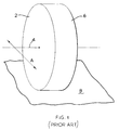
- Figure 1 shows the known prior art, namely a wheel (2).
- the wheel (2) is capable of rotating about an axis (4), its direction of travel being perpendicular to the axis (4) of rotation (indicated by Arrow A).
- a ground engagement surface (6) Around the periphery of the wheel (2) is a ground engagement surface (6), part of which is in contact with the ground (8) across which the wheel (2) is travelling.
- the ground engagement surface (6) makes frictional contact with the ground (8) to prevent the ground engagement surface (6) and hence the wheel (2) from sliding over the ground (8).
- Movement of the wheel (2) is generated by rotation of the wheel about its axis.
- the wheel (2) can be either driven by a motor of some kind or can freely rotate about its axis (4).
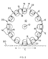
- Figure 2 shows the first embodiment of the present invention.
- the wheel comprises an inner section (10) having a substantially circular cross section and which is capable of rotating about an axis (which projects perpendicularly out of the page of Figure 2 at a point indicated by reference number (12)).
- Around the edge (14) of the inner section (10) are two lines of rollers (16).
- Figure 2 only shows one line of rollers, the second being omitted for the clarity of Figure 2.
- Figure 3 shows the two lines of rollers (16, 17).
- the rollers in the first line are indicated by reference number (16), the rollers in the second line by reference number (17).
- the rollers (16, 17) are rotatably mounted in recesses (18) formed around the edge (14) as shown in Figure 2.
- the rollers (16, 17) are able to freely rotate about their axes (19) of rotation which is at a tangent to the axis of the inner section (10).
- rollers (16, 17) When the wheel is located on the ground (20), the rollers (16, 17) which are beneath the wheel make contact with the ground (20). As the wheel rolls over the ground (in the direction indicated by Arrow C) it rotates about its axis, so that successive rollers (16, 17) in each line of rollers (16, 17) come into and out of contact with the ground (20). No part of the inner section (10) of the wheel comes into contact with the ground (20), the rollers (16, 17) forming the whole of the ground engagement surface of the wheel. Each of the rollers (16, 17) is made from a material that provides a frictional contact between the periphery of the roller (16, 17) and ground (20).
- the wheel can travel across the ground in a forward/reverse direction of travel (Arrow C) due to the rotation of the wheel about its axis of rotation or sideways parallel to its axis of rotation due to the rotation of the rollers (16, 17), or in other directions due to a combination of the rotation of the wheel about its axis and the rotation of the rollers (16, 17).
- Arrow C forward/reverse direction of travel
- rollers (16, 17) in one line are off-set relative to the rollers in the other line as best shown in Figure 3.
- a gap (22) (as best shown in Figure 2) exists between adjacent rollers (16, 17) in each line.
- Each roller (16, 17) in one line is aligned with a gap in the other line.
- the sides of the rollers (16, 17) are curved along the length of the rollers (the line of curvature is indicated by the line E) so that there is smooth rolling action when the wheel rolls over the ground (20).
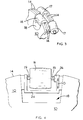
- FIG 4 shows the second embodiment of the present invention.
- the wheel is constructed in a similar manner to that described in the first embodiment.
- each of the rollers (16, 17) is mounted on a support frame (24) and is connected to a control mechanism (26).
- the control mechanism (26) controls the rotation of the roller (16, 17) and is capablc of operating in three modes.
- the roller (16, 1 7) is able to freely rotate about its axis (19) of rotation in the same manner as in thc first embodiment.
- the rollers (16, 17) In the second mode, it applies a frictional force against the rotational movement of the roller (16, 17). Therefore, the rollers (16, 17) will only rotate about its axis (19) when sufficient force is applied to the roller (16, 17).
- control mechanism (26) acts as a brake, locking the roller (16, 17) and preventing it from rotation.
- the roller (16, 17) is locked, the wheel behaves as a conventional wheel.
- the support frame enables the rollers (24) to be moved between two positions (in a direction indicated by Arrow D), a first position where the side of the roller (16, 17) projects beyond the inner section (10) so that it is capable of engaging the ground when the wheel rotates (as shown in Figure 4) and a second position where the roller (16, 17) is retracted into the recess (18) so that the outer edge of the inner section (10) makes contact with the ground.
- the wheel as described in the two embodiments may be constructed so that only a section of periphery comprises rollers. Where the rollers are located around a section of the periphery of the wheel, the wheel shall be able to slide sideways only when that section is in contact with the ground.
- rollers (16, 17) placed around the periphery of a wheel
- the rollers (16, 17) could be used on the ground engaging surface of the band of a track or the outer surface of a roller.
- the rollers (16, 17) arranged around the periphery of the wheel could be replaced by wheels, tracks, or a single roller which extends around part of or the whole periphery of the wheel.
- the invention has been described in relation to a wheel of a vehicle or appliance for traversing over a surface. It will be clear to a person skilled in the art that the invention could be used on rolling mechanisms located within a piece of equipment.
Landscapes
- Engineering & Computer Science (AREA)
- Mechanical Engineering (AREA)
- Soil Working Implements (AREA)
- Road Paving Machines (AREA)
Applications Claiming Priority (2)
| Application Number | Priority Date | Filing Date | Title |
|---|---|---|---|
| GB9818252A GB2340803A (en) | 1998-08-21 | 1998-08-21 | Wheel, roller or track with peripheral rollers |
| GB9818252 | 1998-08-21 |
Publications (1)
| Publication Number | Publication Date |
|---|---|
| EP0983874A2 true EP0983874A2 (fr) | 2000-03-08 |
Family
ID=10837616
Family Applications (1)
| Application Number | Title | Priority Date | Filing Date |
|---|---|---|---|
| EP19990306197 Withdrawn EP0983874A2 (fr) | 1998-08-21 | 1999-08-04 | Roue |
Country Status (2)
| Country | Link |
|---|---|
| EP (1) | EP0983874A2 (fr) |
| GB (1) | GB2340803A (fr) |
Cited By (5)
| Publication number | Priority date | Publication date | Assignee | Title |
|---|---|---|---|---|
| SG106640A1 (en) * | 2001-10-02 | 2004-10-29 | Sawada Mitsuo | Wheel |
| WO2011065598A1 (fr) * | 2009-11-25 | 2011-06-03 | 엘지전자 주식회사 | Aspirateur de type traineau |
| WO2011065599A1 (fr) * | 2009-11-25 | 2011-06-03 | 엘지전자 주식회사 | Aspirateur de type vertical |
| WO2013160653A1 (fr) * | 2012-04-27 | 2013-10-31 | Roger Hiscock | Roue ou pneu |
| CN107310377A (zh) * | 2017-07-19 | 2017-11-03 | 深圳航天科技创新研究院 | 多向滚动装置 |
Families Citing this family (5)
| Publication number | Priority date | Publication date | Assignee | Title |
|---|---|---|---|---|
| GB2408692A (en) * | 2003-12-02 | 2005-06-08 | Rolling Dynamics Ltd | Rider platform capable of longitudinal and lateral rolling |
| JP5682941B2 (ja) * | 2009-02-26 | 2015-03-11 | 国立大学法人九州工業大学 | 全方位移動用車輪 |
| JP6203522B2 (ja) * | 2013-04-16 | 2017-09-27 | 京町産業車輌株式会社 | 車輪 |
| IT201900004829A1 (it) * | 2019-04-01 | 2020-10-01 | Bertele Federica | Tribuna telescopica ad elevata capacita' di spostamento omnidirezionale |
| DE102022000427A1 (de) | 2022-02-04 | 2023-08-10 | Frank Schmauder | Personenfortbewegungsgerät, insbesondere Rollenski, Skateboard oder ähnliches, zur rollenden Fortbewegung auf einem Untergrund |
Family Cites Families (6)
| Publication number | Priority date | Publication date | Assignee | Title |
|---|---|---|---|---|
| US4223753A (en) * | 1977-12-19 | 1980-09-23 | Bradbury Harold M | Omni-directional transport device |
| US4335899A (en) * | 1979-05-18 | 1982-06-22 | Hiscock Roger F | Wheel for toy vehicle |
| KR940009860B1 (ko) * | 1989-12-08 | 1994-10-18 | 가부시끼가이샤 히다찌세이사꾸쇼 | 자주식 수송기구 |
| US5323867A (en) * | 1992-03-06 | 1994-06-28 | Eric J. Allard | Robot transport platform with multi-directional wheels |
| US5312165A (en) * | 1992-11-13 | 1994-05-17 | Fpd Technology, Inc. | Combination brake and wheel system for in-line roller skates and the like |
| US5720529A (en) * | 1996-12-20 | 1998-02-24 | Barron; Bruce J. | Roller skate wheel |
-
1998
- 1998-08-21 GB GB9818252A patent/GB2340803A/en not_active Withdrawn
-
1999
- 1999-08-04 EP EP19990306197 patent/EP0983874A2/fr not_active Withdrawn
Cited By (8)
| Publication number | Priority date | Publication date | Assignee | Title |
|---|---|---|---|---|
| SG106640A1 (en) * | 2001-10-02 | 2004-10-29 | Sawada Mitsuo | Wheel |
| WO2011065598A1 (fr) * | 2009-11-25 | 2011-06-03 | 엘지전자 주식회사 | Aspirateur de type traineau |
| WO2011065599A1 (fr) * | 2009-11-25 | 2011-06-03 | 엘지전자 주식회사 | Aspirateur de type vertical |
| RU2508041C2 (ru) * | 2009-11-25 | 2014-02-27 | ЭлДжи ЭЛЕКТРОНИКС ИНК. | Пылесос вертикального типа |
| WO2013160653A1 (fr) * | 2012-04-27 | 2013-10-31 | Roger Hiscock | Roue ou pneu |
| GB2516404A (en) * | 2012-04-27 | 2015-01-21 | Roger Hiscock | Wheel or tyre |
| US20150144239A1 (en) * | 2012-04-27 | 2015-05-28 | Roger Frederick Hiscock | Wheel or tyre |
| CN107310377A (zh) * | 2017-07-19 | 2017-11-03 | 深圳航天科技创新研究院 | 多向滚动装置 |
Also Published As
| Publication number | Publication date |
|---|---|
| GB9818252D0 (en) | 1998-10-14 |
| GB2340803A (en) | 2000-03-01 |
Similar Documents
| Publication | Publication Date | Title |
|---|---|---|
| DE69520797T2 (de) | Fahrzeug mit Schwenkrollen | |
| EP1875888B1 (fr) | Véhicule motorisé à direction différentielle | |
| US8028775B2 (en) | Spherical mobility mechanism | |
| EP0983874A2 (fr) | Roue | |
| WO2006068007A1 (fr) | Roue mobile omnidirectionnelle, dispositif mobile, dispositif de transport et dispositif de massage | |
| US20110094805A1 (en) | Omni-directional vehicle with full circumferential revolvable hitch | |
| US20200391545A1 (en) | Omni-wheel brake devices and methods for braking an omni-wheel | |
| US5139279A (en) | Parallel-aligned all-wheel steered vehicle | |
| CA2372621A1 (fr) | Essieu pour vehicule | |
| JPH10315701A (ja) | 車両用タイヤ、及びそれを用いた車両 | |
| JP2985269B2 (ja) | クローラ走行車 | |
| JP3184458B2 (ja) | 手押し台車 | |
| JPH11286262A (ja) | 自動車の移動用台車 | |
| JP3992142B2 (ja) | 回転体付き車輪 | |
| JP3245736B2 (ja) | フロントアクスルとリヤアクスルによる車両用操縦装置 | |
| JPH0328002A (ja) | 移動車両用タイヤ | |
| KR100314916B1 (ko) | 자동차의 이동용 대차 | |
| JP4334121B2 (ja) | 車椅子 | |
| JP4610700B2 (ja) | トラクタ作業機における自由車輪 | |
| JP2869368B2 (ja) | キャスター | |
| DE102017010427A1 (de) | Lenksystem für bewegbare angetriebene Vorrichtungen | |
| JPH0597069A (ja) | クローラ式走行車 | |
| JPS6136444Y2 (fr) | ||
| JPH0127909B2 (fr) | ||
| JPH06270852A (ja) | 無限軌道車のクロ−ラ支持及び駆動装置 |
Legal Events
| Date | Code | Title | Description |
|---|---|---|---|
| PUAI | Public reference made under article 153(3) epc to a published international application that has entered the european phase |
Free format text: ORIGINAL CODE: 0009012 |
|
| AK | Designated contracting states |
Kind code of ref document: A2 Designated state(s): AT BE CH CY DE DK ES FI FR GB GR IE IT LI LU MC NL PT SE |
|
| AX | Request for extension of the european patent |
Free format text: AL;LT;LV;MK;RO;SI |
|
| STAA | Information on the status of an ep patent application or granted ep patent |
Free format text: STATUS: THE APPLICATION IS DEEMED TO BE WITHDRAWN |
|
| 18D | Application deemed to be withdrawn |
Effective date: 20020301 |