EP0983885B1 - Système de distribution d'air pour un dispositif de climatisation - Google Patents
Système de distribution d'air pour un dispositif de climatisation Download PDFInfo
- Publication number
- EP0983885B1 EP0983885B1 EP99116189A EP99116189A EP0983885B1 EP 0983885 B1 EP0983885 B1 EP 0983885B1 EP 99116189 A EP99116189 A EP 99116189A EP 99116189 A EP99116189 A EP 99116189A EP 0983885 B1 EP0983885 B1 EP 0983885B1
- Authority
- EP
- European Patent Office
- Prior art keywords
- seal member
- seal
- case
- corner portion
- door
- Prior art date
- Legal status (The legal status is an assumption and is not a legal conclusion. Google has not performed a legal analysis and makes no representation as to the accuracy of the status listed.)
- Expired - Lifetime
Links
Images





Classifications
-
- B—PERFORMING OPERATIONS; TRANSPORTING
- B60—VEHICLES IN GENERAL
- B60H—ARRANGEMENTS OF HEATING, COOLING, VENTILATING OR OTHER AIR-TREATING DEVICES SPECIALLY ADAPTED FOR PASSENGER OR GOODS SPACES OF VEHICLES
- B60H1/00—Heating, cooling or ventilating devices
- B60H1/00642—Control systems or circuits; Control members or indication devices for heating, cooling or ventilating devices
- B60H1/00664—Construction or arrangement of damper doors
- B60H1/00671—Damper doors moved by rotation; Grilles
- B60H1/00678—Damper doors moved by rotation; Grilles the axis of rotation being in the door plane, e.g. butterfly doors
-
- B—PERFORMING OPERATIONS; TRANSPORTING
- B60—VEHICLES IN GENERAL
- B60H—ARRANGEMENTS OF HEATING, COOLING, VENTILATING OR OTHER AIR-TREATING DEVICES SPECIALLY ADAPTED FOR PASSENGER OR GOODS SPACES OF VEHICLES
- B60H1/00—Heating, cooling or ventilating devices
- B60H1/00642—Control systems or circuits; Control members or indication devices for heating, cooling or ventilating devices
- B60H1/00664—Construction or arrangement of damper doors
- B60H2001/00714—Details of seals of damper doors
Definitions
- the present invention relates to an air passage switching system having a door for opening and closing an air passage through which air flows.
- the air passage switching system is suitable for an air outlet mode switching unit for a vehicle air conditioner.
- a generic system according to the preamble of claim 1 and 7 is know from FR-A-2669277.
- a conventional air passage switching system for an air conditioner of a vehicle has an air conditioning case for forming an air passage, and a butterfly door for switching the air passage.
- a rotation shaft for rotating the butterfly door is disposed at side end centers of the door.
- the butterfly door is rotatably held in the air conditioning case to be rotated by the rotation shaft.
- the butterfly door includes a door body portion made of resin having a high rigidity, and a lip-seal like seal member made of an elastomer.
- the seal member is formed into a thin-plate like (i.e., flat sheet) integrally with the door body portion on the outer peripheral portion of the door body portion.
- the seal member is formed into the thin-plate like to have a low rigidity, the seal member is readily deformed due to inner shrinking force, and is readily bent upwardly on a corner portion.
- the rigidity of the seal member 202 is increased, and the seal member 202 is not readily deformed.
- the T-shaped or Y-shaped end section is difficult to be molded, and the producing cost of the seal member 202 is increased.
- the thickness of the top end of the seal member 202 becomes larger due to the T-shaped or Y-shaped end section, an area of an air passage is reduced and pressure loss of the air passage is increased when the door is opened.
- an object of the present invention to provide an air passage switching system which opens and closes an air passage by using a door where a thin and flat plate-like seal member made of an elastic material is attached to an outer peripheral portion of a door body.
- the door is produced in low cost while preventing air leak due to deformation of the seal member.
- an air passage switching system includes a door for opening and closing an opening of a case.
- the door includes a door body made of a material having a rigidity higher than a predetermined value, and a seal member made of an elastic material having a heat contraction and being attached to an outer peripheral portion of the door body.
- the seal member continually extends from the outer peripheral portion of the door body toward an outer side to have a thin plate-like shape.
- the case has a case seal surface around the opening
- the seal member of the door is press-fitted to the case seal surface to have a predetermined deformation amount when the opening is closed
- the seal member has inner stress (i.e., inner contracting force) generated during molding
- the seal member and the case seal surface are provided in such a manner that the predetermined deformation amount of the seal member when the seal member is press-fitted to the case seal surface is made larger than a deformation amount of the seal member due to the inner stress.
- the seal member and the case seal surface are provided in such a manner that the deformation amount of the seal member when being press-fitted to the case seal surface is made larger than the deformation amount of the seal member due to the inner stress. Therefore, on the corner portion of the seal member, the air leak due to deformation of the seal member can be effectively prevented.
- the seal member has an outer peripheral curvature radius (R D ) on a corner portion
- the seal member is press-fitted to the case seal surface along a seal line when the opening is closed
- the case seal surface has an inner peripheral curvature radius (R C2 ) on a corner portion of the seal line, corresponding to the corner portion of the seal member
- the inner peripheral curvature radius (R C2 ) is set to be larger than the outer peripheral curvature radius (R D ). Therefore, when the opening is closed, an inner peripheral portion of the case seal surface tightly contacts the seal member on the corner portion. That is, the corner portion of the seal member can be beforehand elastically deformed from an initial using time by an elastic deformation amount larger than the deformation amount due to the inner shrinking force. Thus, the air leak due to the inner shrinking force can be further prevented.
- the inner peripheral curvature radius (R C2 ) is set to be in a range of 1.5R D - 4R D , relative to the outer peripheral curvature radius (R D ). Therefore, the clearance between the case seal surface of the case and the door can be further prevented, and an interference between the case seal surface and the door body can be prevented.
- a corner portion of the door body corresponding to the corner portion of the seal member has a protrusion protruding toward the corner portion of the seal member. Therefore, the protrusion dimension of the seal member on the corner portion can be reduced by the protrusion amount of the protrusion of the door body. Accordingly, an upwardly bent amount of the seal member on the corner portion can be reduced, and deformation of the seal member on the corner portion due to dynamical pressure of blown-air can be reduced. As a result, the air leak on the corner portion can be effectively prevented.
- the door body portion including the protrusion is made of a material having a high rigidity, the rigidity of the seal member on the corner portion can be improved by the protrusion, and the deformation of the seal member due to the inner shrinking force on the corner portion can be effectively prevented.
- the protrusion protruding toward the corner portion of the seal member has a smoothly curved outer surface. Therefore, stress with the door opening-closing operation is not collected in the corner portion of the seal member, and the bonding performance between the seal member and the door body can be maintained in a long time.
- An air conditioning unit 10 of an air conditioner for a vehicle is disposed in a passenger compartment at an approximately center portion of an instrument panel (not shown) in a vehicle width direction (i.e., right-left direction).
- the instrument panel is disposed in a front part of the passenger compartment of the vehicle.
- the air conditioning unit 10 is installed in the vehicle to correspond to an arrangement direction of FIG. 1.
- a blower unit (not shown) is disposed in the passenger compartment at a front passenger's side shifted from the air conditioning unit 10 in the vehicle width direction.
- the air conditioning unit 10 has an air conditioning case 11 which forms an air passage for leading air toward the passenger compartment.
- An air inlet 11a through which air is introduced into the air conditioning case 11 is formed on a most front portion of the air conditioning case 11.
- An outlet of the blower unit is connected to the air inlet 11a of the air conditioning case 11, so that air blown by the blower unit flows into the air conditioning case 11 through the air inlet 11a.
- Air introduced into the air conditioning case 11 is cooled by an evaporator 12 of a refrigerant cycle, and then is heated by a heater core 13 which heats air using hot water (i.e., engine cooling water) as a heating source.
- An amount of air passing through the heater core 13 and an amount of air bypassing the heater core 13 are adjusted by a plate-like air mixing door 15 so that the temperature of air to be blown into the passenger compartment is adjusted to have a predetermined temperature.
- the air mixing door 15 is rotated by a rotation shaft 15a in the air conditioning case 11.
- a ratio between an amount of air passing through the heater core 13 and an amount of air passing through a bypass passage 14 through which air bypasses the heater core 13 is adjusted by controlling a rotation position of the air mixing door 15.
- the conditioned air is blown into the passenger compartment through at least one of three opening portions formed in the air conditioning case 11.
- the three opening portions are a face opening 16 through which air is blown toward the head portion of a passenger in the passenger compartment, a defroster opening 17 through which air is blown toward an inner surface of a windshield of the vehicle, and a foot opening 18 through which air is blown toward the foot portion of the passenger.
- the face opening 16, the defroster opening 17, and the foot opening 18 are opened and closed, respectively, by a face door 19, a defroster door 20, and a foot door 21.
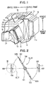
- the face door 19 and the defroster door 20 are butterfly doors as shown in FIGS. 1, 2.
- each of the butterfly doors 19, 20 has a door body 100 formed into an approximate rectangular shape using an inelastic material having a high rigidity, such as resin.
- a rotation shaft 101 for rotating the door body 100 is integrally formed with the door body 100 to extend in a longitudinal direction of the door body 100, and is disposed at a center of the door body 100 in a lateral direction of the door body 100.
- both side ends of each door 19, 20 in the lateral direction are referred to as lateral side ends
- both side ends of each door 19, 20 in the longitudinal direction are referred to as longitudinal side ends.
- a seal member 102 made of an elastic material is attached to an outer peripheral portion of the door body 100 in such a manner that the door body 100 is framed by the seal member 102.
- the seal member 102 is a lip-like seal sheet extending continuously outside from the outer peripheral portion of the door body 100.
- the door body 100 and the seal member 102 can be integrally formed, for example.
- the door body 100 is molded beforehand, is inserted into a mold at a predetermined position, and thereafter, a melted elastic material for forming the seal material is injected into the mold, so that the door body 100 and the seal member 102 can be integrally formed.
- the door body 100 of the door 19, 20 is made of a resin material such as polypropylene, nylon and ABS resin.
- a filler such as glass fiber may be mixed into the resin material of the door body 100 to enhance a strength of the door body 100.
- the seal member 102 is made of elastomer such as olefin elastomer of thermoplastic elastomer (TPE).
- TPE thermoplastic elastomer
- the air conditioning case 11 may be made of the same resin material as that of the door body 100.
- the air conditioning case 11 has ribs 105, 106 protruding from the inner wall of the air conditioning case 11 at the positions forming the face and defroster openings 16, 17.
- the ribs 105, 106 respectively have an inclined seal surface 103, 104.
- each of the face and defroster openings 16, 17 has a rectangular shape corresponding to each rectangular shape of the butterfly doors 19, 20.
- the rib 105 having the seal surface 103 and the rib 106 having the seal surface 104 are formed to be partitioned on right-left sides of the rotation shaft 101, using the rotation shaft 101 of the butterfly door 19, 20 as a boundary.
- FIG. 2 shows an opening state of each butterfly door 19, 20.
- operation force is applied to the rotation shaft 101 in a rotation direction so that the butterfly door 19, 20 is rotated by a predetermined rotation angle in the anticlockwise direction of FIG. 2, an outer peripheral end portion 102b of the seal member 102 of the butterfly door 19, 20 tightly contacts the seal surfaces 103, 104 of the ribs 105, 106 of each opening portion 16, 17. Therefore, the outer peripheral portion of the door body portion 100 can be sealed relative to the air conditioning case 11, and the opening portions 16, 17 of the air conditioning case 11 can be closed by the butterfly doors 19, 20.
- the outer peripheral end portion 102b of the thin-plate like (i.e., flat sheet like) seal member 102 is press-fitted to the ribs 105, 106 of the air conditioning case 11 on both sides of a first end of the door body portion 100 parallel to the rotation shaft 101 and a second end thereof perpendicular to the rotation shaft 101.
- a length of the first end of the door body portion 100 is larger than the second end of the door body portion 100. That is, the first end of the door body portion 100 corresponds to the longitudinal side ends of the door 19, 20, and the second end thereof corresponds to the lateral side ends of the door 19, 20.
- FIG. 4 shows a state in which the outer peripheral end portion 102b of the sheet-like seal member 102 is press-fitted to the inclined seal surface 104 of the rib 106.
- the seal surfaces 103, 104 are formed to be inclined, so that a contacting-surface pressure between the seal member 102 and the air conditioning case 11 is increased. Therefore, sealing-effect for air-tightly sealing the openings 16, 17 of the air conditioning case 11 can be improved.
- Both ends of the rotation shaft 101 of the door body portion 100 of the butterfly door 19, 20 are rotatably held in a shaft receiving hole (not shown) provided in the air conditioning case 11.
- One end of the rotation shaft 101 protrudes to the outer side of the air conditioning case 11, and is connected to a door driving unit (not shown).
- the door driving unit is a manual operation member provided on an operation panel of the vehicle air conditioner, or an actuator using a motor controlled by a control unit.
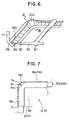
- a curvature radius R C1 of the seal surface 104 (103) of the rib 106 (105) on a corner is equal to or smaller than a curvature radius R D of an outer circular arc portion formed in the corner portion 102a of the seal member 102 (i.e., R C1 ⁇ R D ).
- R D 5 mm
- R C1 5 mm
- the corner portion 102a of the thin-plate like seal member 102 is deformed toward the door body portion 100.
- the outer peripheral end portion 102b of the seal member 102 is bent upwardly on the corner portion 102a, thereby causing the clearance "C” between the seal surface 104 (103) and the outer peripheral end portion 102b on the corner portion 102a.
- the seal member 104 (103) and the seal member 102 are set to have the relationship of R C1 ⁇ R D on the corner portion.
- the chain line "D" in FIGS. 7, 8A, 8B indicates a seal line where the outer peripheral end portion 102b of the seal member 102 is press-fitted to the seal surface 104 (103) of-the air conditioning case 11.
- the inner peripheral circular arc portion on the corner portion of the seal line "D" of the seal surface 104(103) is formed to have a curvature radius Rc2 which is larger than the curvature radius R D of the outer peripheral circular arc portion of the seal member 102 on the corner portion 102a. Therefore, when the doors 19, 20 closes the opening portions 16, 17, the seal member 102 is beforehand elastically deformed from an initial using time by a degree equal to or more than a deformation amount due to the inner shrinking force. That is, the deformation amount of the thin-plate like seal member 102 on the corner portion 102a toward the door body portion 100 is determined by the inner shrinking force of the seal member 102 and the rigidity of the seal member 102.
- the curvature radius R C2 of the inner peripheral circular arc portion of the seal surface 104 (103) on the corner portion of the seal line "D" is set to be larger than the curvature radius RD of the outer peripheral circular arc portion of the corner portion 102a of the seal member 102, as shown in FIGS. 7, 8B, 9B, so that the seal member 102 tightly contacts the inner peripheral circular arc portion of the corner portion of the seal surface 104(103).
- the corner portion 102a of the thin-plate like seal member 102 can be elastically deformed from the initial using time by a deformation amount equal to or more than the deformation amount due to the inner shrinking force of the seal member 102.
- the curvature radius R C2 is preferably in a range of 1.5R D - 4R D .
- the curvature radius R C2 is preferably in a range of 1.5R D - 4R D .
- the curvature radius R C2 is set to be 4 R D or smaller than 4 R D .
- the curvature radius R c2 when the curvature radius R c2 is set in a range of 2R D - 3R D , sufficient seal performance and operation performance of the door 19, 20 are obtained.
- the curvature radius R D when the curvature radius R D is 5 mm, the curvature radius Rc 2 is set in a range of 10-15 mm.
- the door 19, 20 can be produced in low cost because the seal member 102 is formed into the thin-plate like.
- the curvature radius R C2 is set in the range of 1.5R D - 4R D , the air leak due to the deformation of the thin-plate like seal member 102 can be prevented.
- FIGS. 10A-14C A second preferred embodiment of the present invention will be now described with reference to FIGS. 10A-14C.
- the structure for preventing air leak on the corner portion due to the inner shrinking force of the thin-plate like seal member 102 in the above-described first embodiment, the structure for preventing air leak on the corner portion due to the inner shrinking force of the thin-plate like seal member 102.
- the deformation of the corner portion 102a of the thin-plate like seal member 102 due to dynamical pressure of blown air is restricted. Since the dynamical pressure of air blown by the blower unit is applied to the thin-plate like seal member 102, the air leak may be caused in the corner portion 102a of the seal member 102.
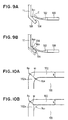
- FIG. 10A shows a corner portion 102a of the thin-plate like seal member 102 of a first comparison example
- FIG. 10B shows a corner portion 102a of the thin-plate like seal member 102 of a second comparison example.
- a protrusion dimension "a1" of the seal member 102 on the corner portion 102a is larger than a protrusion dimension "b" of the seal member 102 on a straight line portion except for the corner portion 102a.
- the protrusion dimension "a1" of the seal member 102 on the corner portion 102a is 14.14 mm.
- the bent deformation amount in an elastic body is in proportion to the third power (i.e., the cube) of the protrusion dimension relative to a certain load.
- the corner portion 102a is greatly deformed in the direction where the dynamical pressure is applied.
- the deformation amount of the corner portion 102a of the seal member 102 due to the dynamical pressure, is L1 which is greatly larger than the deformation amount L2 of the straight line portion, due to the dynamical pressure.
- air leak is caused by the deformation of the corner portion 102a due to the dynamical pressure.
- an angle portion having a right angle is formed instead of the inner peripheral circular portion of the corner portion 102a. Therefore, the corner portion 102a of the seal member 102 has a reduced protrusion dimension "a2".
- the bent deformation of the seal member 102 is repeated with door opening/closing operation, and stress is collected in the angle portion of the seal member 102. Therefore, the seal member 102 is broken from the angle portion, and bonding performance between the seal member 102 and the door body portion 100 may deteriorated.
- a protrusion portion 107 protruding toward the corner portion 102a of the seal member 102 is provided in the corner portion of the door body portion 100, so that the deformation of the corner portion 102a of the seal member 102 due to the dynamical pressure of blown-air is restricted.
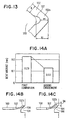
- the protrusion portion 107 protrudes in a smooth curve shape (e.g., circular arc shape).
- the protrusion dimension "a3” is a distance between the top portion of the protrusion portion 107 and the outer peripheral circular arc portion of the corner portion 102a of the seal member 102.
- the dimension "a3" By setting the dimension "a3" to be 1.1b or lower than 1.1b, the deformation amount of the corner portion 102a due to the dynamical pressure can be restricted to be approximately equal to the deformation amount L2 of the straight line portion of the seal member 102, thereby effectively preventing the air leak due to the dynamical pressure.
- the dimension "a3” is set to be 0.5b or larger than 0.5b.
- the protrusion portion 107 protrudes in the smooth curve shape. Therefore, the inner peripheral surface of the corner portion 102a of the seal member 102 is not curved to have an angle portion as described in the comparison example 2, and stress with the door opening/closing operation is not collected. Thus, the bonding performance between the seal material 102 and the door body portion 100 can be maintained in a long time.
- the protrusion dimension "a3" of the corner portion 102a of the seal member 102 is set to be approximately equal to the protrusion dimension "b" of the straight line portion of the seal member 102, and the rigidity of the corner portion 102a of the seal member 102 is improved due to the addition of the protrusion portion 107 having a high rigidity. Therefore, it can prevent the corner portion 102a of the seal member 102 from being bent upwardly due to the inner shrinking force.
- FIG. 14A is a view for explaining the effect of the second embodiment of the present invention.
- b 10 mm
- a1 14.14 mm
- the curvature radius of the protrusion portion 107 is 2 mm
- R D 5 mm
- a3 10.07 mm.
- the other conditions such as the material of the seal member 102 are the same between the second embodiment of the present invention and the first example.
- FIG. 14B is a state before the seal member 102 is placed in a high temperature
- FIG. 14B is a state before the seal member 102 is placed in a high temperature
- the seal member 102 press-fitted to the seal surface 104 is placed in a high temperature of 80 °C for 24 hours.
- the pressure difference between face and back sides of the door is 5333 Pa (40 mmHg).
- the upwardly bent amount of the first comparison example is 0.23 mm
- the upwardly bent amount of the second embodiment of the present invention is 0.13 mm, as shown in FIG. 14A.
- the air leak flow amount from the corner portion 102a of the seal member 102 is 2.9 m 3 /h.
- the air leak flow amount from the corner portion 102a of the seal member 102 is 0.9 m 3 /h.
- the present invention may be applied to an air mixing door for adjusting temperature of air blown into the passenger compartment.
- the present invention is not limited to the air passage switching system of the air conditioner for the vehicle, but may be applied to an air passage switching system of various use.
- the present invention is applied to the butterfly doors 19, 20 each having the rotation shaft 101 at a center portion of the door body portion 100.
- the present invention may be applied to a door such as the door 15 where the rotation shaft 15a is disposed at an end portion of the door body portion, when a lip-like seal member is attached to an outer peripheral end of a door body portion.
Landscapes
- Physics & Mathematics (AREA)
- Thermal Sciences (AREA)
- Engineering & Computer Science (AREA)
- Mechanical Engineering (AREA)
- Air-Conditioning For Vehicles (AREA)
- Air-Flow Control Members (AREA)
Claims (11)
- Système de commutation de passages d'air comprenant :un boítier (11) pour former un passage d'air à travers lequel l'air s'écoule, ledit passage d'air comprenant une ouverture (16, 17) ;une porte (19, 20) disposée dans le boítier, pour ouverture et fermeture de ladite ouverture, ladite porte incluantun corps de porte (100) constitué d'un matériau ayant une rigidité supérieure à une valeur prédéterminée, etun élément d'étanchéité (102) constitué d'un matériau élastique ayant un retrait à la chaleur et étant fixé à une partie périphérique externe dudit corps de porte, ledit élément d'étanchéité s'étendant en continu de la partie périphérique externe dudit corps de porte vers un côté externe pour avoir une forme du type plaque mince, dans lequel :ledit boítier comporte une surface d'étanchéité de boítier (103, 104) autour de ladite ouverture ;ledit élément d'étanchéité de ladite porte est ajusté par pression sur ladite surface d'étanchéité de boítier pour avoir une quantité de déformation prédéterminée lorsque ladite ouverture est fermée ; caractérisé en ce queledit élément d'étanchéité a une contrainte interne générée pendant le moulage ; etledit élément d'étanchéité et ladite surface d'étanchéité, de boítier sont ménagés d'une manière telle que la quantité de déformation prédéterminée dudit élément d'étanchéité lorsque ledit élément d'étanchéité est ajusté par pression sur ladite surface d'étanchéité de boítier, est rendue supérieure à une quantité de déformation dudit élément d'étanchéité due à la contrainte interne.
- Système de commutation de passage d'air selon la revendication 1, dans lequel :ledit élément d'étanchéité comprend une partie angulaire incurvée (102a) ; etledit élément d'étanchéité et ladite surface d'étanchéité de boítier sont ménagés d'une manière telle que la quantité de déformation dudit élément d'étanchéité, lorsque ledit élément d'étanchéité est ajusté par pression sur ladite surface d'étanchéité de boítier, est rendue plus grande que la quantité de déformation dudit élément d'étanchéité due à la contrainte interne sur ladite partie angulaire.
- Système de commutation de passage d'air selon la revendication 2, dans lequel :ledit élément d'étanchéité a un rayon de courbure périphérique externe (RD) sur ladite partie angulaire ;ledit élément d'étanchéité est ajusté par pression sur ladite surface d'étanchéité de boítier suivant une ligne d'étanchéité lorsque ladite ouverture est fermée ;ladite surface d'étanchéité de boítier a un rayon de courbure périphérique interne (RC2) sur une partie angulaire de la ligne d'étanchéité correspondant à ladite partie angulaire ; etle rayon de courbure périphérique interne (RC2) de ladite surface d'étanchéité de boítier est établi pour être plus grand que le rayon de courbure périphérique externe (RD) dudit élément d'étanchéité.
- Système de commutation de passage d'air selon la revendication 3, dans lequel le rayon de courbure périphérique interne (RC2) de ladite surface d'étanchéité de boítier est établi pour être dans une gamme de 1,5RD à 4RD par rapport au rayon de courbure périphérique externe (RD) dudit élément d'étanchéité.
- Système de commutation de passage d'air selon la revendication 1, dans lequel :ledit élément d'étanchéité comprend une partie angulaire (102a) ; etledit corps de porte comporte une saillie (107) dépassant vers ladite partie angulaire dudit élément d'étanchéité.
- Système de commutation de passage d'air selon l'une quelconque des revendications 1 à 5, dans lequel :ladite porte comporte un axe de rotation (101) pour rotation dudit corps de porte ; etledit axe de rotation s'étend dans une direction longitudinale de ladite porte.
- Système de commutation de passage d'air comprenant :un boítier (11) pour la formation d'un passage d'air à travers lequel l'air s'écoule, ledit passage d'air comprenant une ouverture (16, 17) ;une porte (19, 20) disposée dans ledit boítier, pour ouverture et fermeture de ladite ouverture, ladite porte incluantun corps de porte (100) constitué d'un matériau ayant une rigidité plus élevée qu'une valeur prédéterminée, etun élément d'étanchéité (102) constitué d'un matériau élastique et étant fixé à une partie périphérique externe dudit corps de porte, ledit élément d'étanchéité s'étendant en continu de la partie périphérique externe dudit corps de porte vers un côté externe pour avoir une forme du type plaque mince, dans lequel :ledit boítier comprend une surface d'étanchéité de boítier (103, 104) autour de ladite ouverture ;ledit élément d'étanchéité de ladite porte est ajusté par pression sur ladite surface d'étanchéité de boítier lorsque ladite ouverture est fermée ; caractérisé en ce queledit élément d'étanchéité comprend une partie angulaire (102a) ; etledit corps de porte porte une saillie (107) dépassant vers ladite partie angulaire dudit élément d'étanchéité.
- Système de commutation de passage d'air selon la revendication 7, dans lequel :ladite saillie dépassant vers ladite partie angulaire dudit élément d'étanchéité comprend une surface externe incurvée.
- Système de commutation de passage d'air selon l'une quelconque des revendications 7 et 8, dans lequel :ledit corps de porte comporte une partie de ligne rectiligne, sauf en ce qui concerne une partie angulaire ;ledit élément d'étanchéité s'étendant de ladite partie de ligne rectiligne dudit corps de porte a une dimension formant saillie (b) ; etladite partie angulaire dudit élément d'étanchéité s'étendant de ladite saillie dudit corps de porte à une dimension formant saillie (a3), la dimension formant saillie (a3) étant dans une gamme de 0,5b à 1,1b par rapport à ladite dimension formant saillie (b).
- Système de commutation de passage d'air selon l'une quelconque des revendications 7 à 9, dans lequel :ledit élément d'étanchéité a un rayon de courbure périphérique externe (RD) sur ladite partie angulaire ;ledit élément d'étanchéité est ajusté par pression sur ladite surface d'étanchéité de boítier suivant une ligne d'étanchéité lorsque ladite ouverture est fermée ;ladite surface d'étanchéité de boítier a un rayon de courbure périphérique interne (RC2) sur la partie angulaire de la ligne d'étanchéité ; etle rayon de courbure périphérique interne (RC2) de ladite surface d'étanchéité de boítier est établi pour être plus grand que le rayon de courbure périphérique externe (RD) dudit élément d'étanchéité.
- Système de commutation de passage d'air selon la revendication 10, dans lequel le rayon de courbure périphérique interne (RC2) de ladite surface d'étanchéité de boítier est établi pour être dans une gamme de 1,5RD à 4RD par rapport au rayon de courbure périphérique externe (RD) dudit élément d'étanchéité.
Applications Claiming Priority (4)
| Application Number | Priority Date | Filing Date | Title |
|---|---|---|---|
| JP23902998 | 1998-08-25 | ||
| JP23902998 | 1998-08-25 | ||
| JP20958799 | 1999-07-23 | ||
| JP20958799A JP4281160B2 (ja) | 1998-08-25 | 1999-07-23 | 通風路切替装置 |
Publications (3)
| Publication Number | Publication Date |
|---|---|
| EP0983885A2 EP0983885A2 (fr) | 2000-03-08 |
| EP0983885A3 EP0983885A3 (fr) | 2001-04-04 |
| EP0983885B1 true EP0983885B1 (fr) | 2002-07-17 |
Family
ID=26517548
Family Applications (1)
| Application Number | Title | Priority Date | Filing Date |
|---|---|---|---|
| EP99116189A Expired - Lifetime EP0983885B1 (fr) | 1998-08-25 | 1999-08-24 | Système de distribution d'air pour un dispositif de climatisation |
Country Status (4)
| Country | Link |
|---|---|
| US (1) | US6193600B1 (fr) |
| EP (1) | EP0983885B1 (fr) |
| JP (1) | JP4281160B2 (fr) |
| DE (1) | DE69902129T2 (fr) |
Families Citing this family (31)
| Publication number | Priority date | Publication date | Assignee | Title |
|---|---|---|---|---|
| NO986020A (no) * | 1998-12-21 | 2000-05-08 | Ims Ind Og Montasjeservice As | Utskiftbar pakning for vanntette og brannsikre skyvedører |
| JP2002243262A (ja) * | 2001-02-21 | 2002-08-28 | Zexel Valeo Climate Control Corp | 車両用空調装置 |
| JP2002307928A (ja) * | 2001-04-10 | 2002-10-23 | Zexel Valeo Climate Control Corp | 車両用空調装置の内外気切替ドア |
| US6540604B1 (en) * | 2001-09-20 | 2003-04-01 | Visteon Global Technologies, Inc. | Apparatus for directing air flow to a passenger compartment of a motor vehicle |
| DE10210975B4 (de) * | 2002-03-13 | 2008-07-31 | Robert Bosch Gmbh | Personenindividuelles Notfallerkennungssystem |
| ITBO20020303A1 (it) * | 2002-05-17 | 2003-11-17 | Magneti Marelli Powertrain Spa | Nuovi otturatori per valvole a farfalla |
| JP3999071B2 (ja) * | 2002-08-20 | 2007-10-31 | 株式会社デンソー | 通風路切替装置の製造方法 |
| GB0308580D0 (en) * | 2003-04-14 | 2003-05-21 | Delphi Tech Inc | Flap valve arrangement |
| JP3894157B2 (ja) * | 2003-05-07 | 2007-03-14 | 株式会社デンソー | 車両用空調装置 |
| JP4396226B2 (ja) * | 2003-11-04 | 2010-01-13 | 株式会社デンソー | 空気通路開閉装置 |
| DE10361108A1 (de) * | 2003-12-22 | 2005-07-21 | Behr Gmbh & Co. Kg | Vorrichtung zur Luftmengenregelung, insbesondere für eine Kraftfahrzeug-Klimaanlage |
| GB0419061D0 (en) * | 2004-08-27 | 2004-09-29 | Delphi Tech Inc | Flap valve arrangement |
| JP2008523344A (ja) * | 2004-12-10 | 2008-07-03 | ベーア ゲーエムベーハー ウント ツェーオー カーゲー | 自動車の換気システムのフラップ |
| JP4618193B2 (ja) * | 2006-06-05 | 2011-01-26 | 株式会社デンソー | 空気通路開閉装置 |
| JP4591420B2 (ja) * | 2006-07-25 | 2010-12-01 | 株式会社デンソー | 空気通路開閉装置 |
| US8029344B2 (en) * | 2006-11-29 | 2011-10-04 | Ford Motor Company | Door assembly for climate control system |
| WO2008147065A1 (fr) * | 2007-05-29 | 2008-12-04 | Halla Climate Control Corporation | Porte pour conditionneur d'air de véhicules |
| KR101375118B1 (ko) * | 2007-12-20 | 2014-03-17 | 한라비스테온공조 주식회사 | 차량 공조장치용 도어 |
| FR2923541B1 (fr) * | 2007-11-13 | 2009-12-11 | Snecma | Vanne de decharge dans une turbomachine |
| KR101512675B1 (ko) | 2008-12-23 | 2015-04-16 | 한라비스테온공조 주식회사 | 실링부재 일체형 도어 |
| JP5470084B2 (ja) * | 2010-02-17 | 2014-04-16 | 株式会社ケーヒン | スライドドア装置 |
| JP5582835B2 (ja) * | 2010-03-19 | 2014-09-03 | 日本プラスト株式会社 | 風量調整装置 |
| US20110319005A1 (en) * | 2010-06-25 | 2011-12-29 | Koji Sawada | Damper plate |
| DE102013219811A1 (de) * | 2013-09-30 | 2015-04-02 | Behr Gmbh & Co. Kg | Klimaanlage |
| DE102015200187A1 (de) * | 2014-12-19 | 2016-06-23 | Continental Automotive Gmbh | Ventilvorrichtung in einem Kraftfahrzeug und Verfahren zur Herstellung |
| JP2017094753A (ja) * | 2015-11-18 | 2017-06-01 | 株式会社ヴァレオジャパン | 車両用空調ユニット |
| US10632819B2 (en) * | 2016-03-31 | 2020-04-28 | Denso International America, Inc. | Demist control for HVAC |
| JP6825310B2 (ja) * | 2016-11-07 | 2021-02-03 | アイシン精機株式会社 | 吸気装置および弁体の製造方法 |
| FR3121966A1 (fr) * | 2021-04-16 | 2022-10-21 | Faurecia Systemes D'echappement | Vanne d’échappement silencieuse |
| KR102574773B1 (ko) * | 2021-07-28 | 2023-09-07 | 에코플라스틱 주식회사 | 차량용 에어벤트의 댐퍼 |
| EP4173832A1 (fr) | 2021-11-02 | 2023-05-03 | Bobst Mex Sa | Méthode de contrôle d'un dispositif d'impression et dispositif d'impression |
Family Cites Families (10)
| Publication number | Priority date | Publication date | Assignee | Title |
|---|---|---|---|---|
| US3308745A (en) * | 1965-09-10 | 1967-03-14 | Davies Charles | Air diffuser |
| US4402586A (en) * | 1980-08-04 | 1983-09-06 | Canon Kabushiki Kaisha | Focusing system |
| FR2510706B1 (fr) * | 1981-07-28 | 1985-11-22 | Valeo | Volet de commande d'un debit d'air dans une canalisation, en particulier dans une installation de chauffage ou de climatisation pour vehicule automobile |
| FR2550848B1 (fr) * | 1983-08-18 | 1988-08-12 | Valeo | Volet, en particulier pour installation de chauffage ou de climatisation d'un habitacle de vehicule, et son procede de fabrication |
| FR2669277B1 (fr) * | 1990-11-16 | 1994-09-30 | Valeo | Volet silencieux pour installation de chauffage de vehicule automobile. |
| DE59205123D1 (de) * | 1992-11-26 | 1996-02-29 | Siemens Ag | Luftklappe für eine Heiz- und/oder Klimaanlage, insbesondere in einem Kraftfahrzeug |
| ES2076886B1 (es) * | 1992-12-22 | 1998-04-16 | Behr Gmbh & Co | Valvula para el cierre de conductos de aire y conducto de aire que la incorpora. |
| DE4329527A1 (de) * | 1993-09-02 | 1995-03-09 | Mann & Hummel Filter | Drosseleinrichtung |
| FR2748308B1 (fr) * | 1996-05-06 | 1998-06-26 | Valeo Climatisation | Volet pivotant a levre d'etancheite pour dispositif de ventilation |
| JP3840773B2 (ja) * | 1997-12-24 | 2006-11-01 | 株式会社デンソー | 通風路切替装置 |
-
1999
- 1999-07-23 JP JP20958799A patent/JP4281160B2/ja not_active Expired - Fee Related
- 1999-08-24 DE DE69902129T patent/DE69902129T2/de not_active Expired - Lifetime
- 1999-08-24 US US09/379,873 patent/US6193600B1/en not_active Expired - Lifetime
- 1999-08-24 EP EP99116189A patent/EP0983885B1/fr not_active Expired - Lifetime
Also Published As
| Publication number | Publication date |
|---|---|
| US6193600B1 (en) | 2001-02-27 |
| EP0983885A2 (fr) | 2000-03-08 |
| EP0983885A3 (fr) | 2001-04-04 |
| JP2000135912A (ja) | 2000-05-16 |
| DE69902129T2 (de) | 2002-12-05 |
| DE69902129D1 (de) | 2002-08-22 |
| JP4281160B2 (ja) | 2009-06-17 |
Similar Documents
| Publication | Publication Date | Title |
|---|---|---|
| US6193600B1 (en) | Air passage switching system for air conditioner | |
| EP0925969B1 (fr) | Système de distribution d'air pour un dispositif de climatisation | |
| JP3575495B2 (ja) | 車両用空気調和装置 | |
| EP0681934B1 (fr) | Dispositif de distribution d'air et appareil de climatisation pour véhicules | |
| US6669548B2 (en) | Inside/outside air switching device with rotary door, and vehicle air conditioner using the same | |
| US6688964B2 (en) | Air passage opening/closing device and vehicle air conditioner using the same | |
| US20040093884A1 (en) | Vehicle air conditioner | |
| US7950444B2 (en) | Automotive air conditioning system | |
| US7694729B2 (en) | Air passage opening/closing device | |
| US6736190B2 (en) | Vehicle air conditioner | |
| US6092592A (en) | Air conditioner for vehicle | |
| US6913529B2 (en) | Air passage switching device and vehicle air conditioner using the same | |
| US6852024B2 (en) | Air passage switching device and vehicle air conditioner using the same | |
| US7478666B2 (en) | Vehicle air conditioner | |
| US20080026687A1 (en) | Passage opening and closing apparatus | |
| US20040038639A1 (en) | Air passage switching system and manufacturing method of switching door | |
| US6641768B2 (en) | Method for manufacturing an air passage switching door | |
| US6920921B2 (en) | Air conditioner for vehicles with right steering wheel and left steering wheel | |
| US6354169B1 (en) | Link lever system for vehicle air conditioner | |
| JP3781144B2 (ja) | 自動車用空気調和装置のドア構造 | |
| JP4277644B2 (ja) | 車両用空調装置 | |
| US5992506A (en) | Air conditioning apparatus for vehicle | |
| KR101450632B1 (ko) | 차량 공조장치용 도어 | |
| JP3933026B2 (ja) | 空気通路開閉装置およびその製造方法 | |
| JPH11115457A (ja) | 自動車用空気調和装置 |
Legal Events
| Date | Code | Title | Description |
|---|---|---|---|
| PUAI | Public reference made under article 153(3) epc to a published international application that has entered the european phase |
Free format text: ORIGINAL CODE: 0009012 |
|
| AK | Designated contracting states |
Kind code of ref document: A2 Designated state(s): DE FR IT |
|
| AX | Request for extension of the european patent |
Free format text: AL;LT;LV;MK;RO;SI |
|
| PUAL | Search report despatched |
Free format text: ORIGINAL CODE: 0009013 |
|
| AK | Designated contracting states |
Kind code of ref document: A3 Designated state(s): AT BE CH CY DE DK ES FI FR GB GR IE IT LI LU MC NL PT SE |
|
| AX | Request for extension of the european patent |
Free format text: AL;LT;LV;MK;RO;SI |
|
| 17P | Request for examination filed |
Effective date: 20010510 |
|
| GRAG | Despatch of communication of intention to grant |
Free format text: ORIGINAL CODE: EPIDOS AGRA |
|
| RIN1 | Information on inventor provided before grant (corrected) |
Inventor name: BANNO, KOUSEI, INTELLECTUAL PROPERTY CENTER Inventor name: ITO, MASAHIRO, INTELLECTUAL PROPERTY CENTER |
|
| 17Q | First examination report despatched |
Effective date: 20010813 |
|
| AKX | Designation fees paid |
Free format text: DE FR IT |
|
| GRAG | Despatch of communication of intention to grant |
Free format text: ORIGINAL CODE: EPIDOS AGRA |
|
| GRAH | Despatch of communication of intention to grant a patent |
Free format text: ORIGINAL CODE: EPIDOS IGRA |
|
| GRAH | Despatch of communication of intention to grant a patent |
Free format text: ORIGINAL CODE: EPIDOS IGRA |
|
| GRAA | (expected) grant |
Free format text: ORIGINAL CODE: 0009210 |
|
| AK | Designated contracting states |
Kind code of ref document: B1 Designated state(s): DE FR IT |
|
| REF | Corresponds to: |
Ref document number: 69902129 Country of ref document: DE Date of ref document: 20020822 |
|
| ET | Fr: translation filed | ||
| PLBE | No opposition filed within time limit |
Free format text: ORIGINAL CODE: 0009261 |
|
| STAA | Information on the status of an ep patent application or granted ep patent |
Free format text: STATUS: NO OPPOSITION FILED WITHIN TIME LIMIT |
|
| 26N | No opposition filed |
Effective date: 20030422 |
|
| PGFP | Annual fee paid to national office [announced via postgrant information from national office to epo] |
Ref country code: IT Payment date: 20110813 Year of fee payment: 13 |
|
| PG25 | Lapsed in a contracting state [announced via postgrant information from national office to epo] |
Ref country code: IT Free format text: LAPSE BECAUSE OF NON-PAYMENT OF DUE FEES Effective date: 20120824 |
|
| PGFP | Annual fee paid to national office [announced via postgrant information from national office to epo] |
Ref country code: DE Payment date: 20140821 Year of fee payment: 16 |
|
| PGFP | Annual fee paid to national office [announced via postgrant information from national office to epo] |
Ref country code: FR Payment date: 20140821 Year of fee payment: 16 |
|
| REG | Reference to a national code |
Ref country code: DE Ref legal event code: R119 Ref document number: 69902129 Country of ref document: DE |
|
| REG | Reference to a national code |
Ref country code: FR Ref legal event code: ST Effective date: 20160429 |
|
| PG25 | Lapsed in a contracting state [announced via postgrant information from national office to epo] |
Ref country code: DE Free format text: LAPSE BECAUSE OF NON-PAYMENT OF DUE FEES Effective date: 20160301 |
|
| PG25 | Lapsed in a contracting state [announced via postgrant information from national office to epo] |
Ref country code: FR Free format text: LAPSE BECAUSE OF NON-PAYMENT OF DUE FEES Effective date: 20150831 |