EP0985562B1 - Fahrzeugrad - Google Patents
Fahrzeugrad Download PDFInfo
- Publication number
- EP0985562B1 EP0985562B1 EP99114411A EP99114411A EP0985562B1 EP 0985562 B1 EP0985562 B1 EP 0985562B1 EP 99114411 A EP99114411 A EP 99114411A EP 99114411 A EP99114411 A EP 99114411A EP 0985562 B1 EP0985562 B1 EP 0985562B1
- Authority
- EP
- European Patent Office
- Prior art keywords
- rim
- valve body
- vehicle wheel
- bore
- sealing
- Prior art date
- Legal status (The legal status is an assumption and is not a legal conclusion. Google has not performed a legal analysis and makes no representation as to the accuracy of the status listed.)
- Expired - Lifetime
Links
Images
Classifications
-
- B—PERFORMING OPERATIONS; TRANSPORTING
- B60—VEHICLES IN GENERAL
- B60C—VEHICLE TYRES; TYRE INFLATION; TYRE CHANGING; CONNECTING VALVES TO INFLATABLE ELASTIC BODIES IN GENERAL; DEVICES OR ARRANGEMENTS RELATED TO TYRES
- B60C29/00—Arrangements of tyre-inflating valves to tyres or rims; Accessories for tyre-inflating valves, not otherwise provided for
- B60C29/02—Connection to rims
-
- B—PERFORMING OPERATIONS; TRANSPORTING
- B60—VEHICLES IN GENERAL
- B60B—VEHICLE WHEELS; CASTORS; AXLES FOR WHEELS OR CASTORS; INCREASING WHEEL ADHESION
- B60B21/00—Rims
Definitions
- the invention relates to a vehicle wheel, in particular to a two-part Vehicle wheel, with an inserted valve body according to the preamble of Claim 1.
- EP 0 032 747 A1 describes a one-piece vehicle wheel with a valve in one Rim shoulder known. To seal this valve against the Inside the tire, an O-ring is provided on the inside of the collar of the valve body and from the outside a nut is screwed onto the valve body, which is partly in a hole in the rim shoulder protrudes.
- the object of the invention is in a two-part vehicle wheel with a cavity insert a sealed valve between the rim shoulders.
- the main advantages achieved with the invention are that at one two-piece wheel, which one between the rim shoulders of each wheel part Has cavity, the circumferential an annular space between the rim shoulders forms to use a valve such that both the valve body to the interior of the Tire is secured as well as to the cavity.
- this is achieved by a sealing sleeve arranged on the valve body achieved. This is in the respective bore of the rim flange from the rim and from Rim star pressed in, clamped or the like held.
- the sleeve is in the bore of the rim between the valve body and pinched the bore, with an opposite free end of the elastic Sealing sleeve tightly embraces the valve body.
- an annular groove in the Sealing sleeve this is in the bore of the rim shoulder of the rim star held.
- the seal in particular in one Steel valve, can be seen from the outside of the rim shoulder Rim star using an elastic sealing ring. This one is on the valve body screw-on adapter sleeve in a shoulder of the bore Rim shoulder of the rim star held.
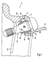
- Both wheel parts 2 and 3 are at least in the area 4 and 5 connected.
- the rim shoulders 6 and 7 of the wheel spider 2 and the rim 3 form between them a cavity 8, which can be designed as an annular space.
- the valve 9 or the valve body 9a is interposed with an elastic one Sealing sleeve 10 inserted into bores 11, 12 of the rim shoulders 6, 7.
- the Rim shoulder 7 is the sealing sleeve 10 between the bore 12 and the Valve body 9a clamped.
- an annular groove 13 of the sleeve 10 this is in the Bore 11 of the rim star 2 held.
- the protruding free end 14 of the Sealing sleeve 10 seals around the valve body 9a.
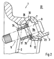
- valve 9 or the valve body 9a by means of a sealing washer 20 and a Collet 21 sealed to the cavity 8 and 22 to the tire interior.
- the sealing washer 20 is in a shoulder 23 of the bore 12 in the Rim shoulder 6 of the rim star 2 held. From the outside, the clamping sleeve 21 stretched against the sealing washer 20, for which purpose a thread on the valve body 9a 24 can be provided.
- a collar 25 of the clamping sleeve 21 presses against the sealing ring 21 and against a shoulder 26 of the rim shoulder 6 and thus causes a seal of the Valve body 9a towards the cavity 8 and the tire interior 22.
Landscapes
- Engineering & Computer Science (AREA)
- Mechanical Engineering (AREA)
- Check Valves (AREA)
- Tires In General (AREA)
- Arrangement Or Mounting Of Propulsion Units For Vehicles (AREA)
- Vehicle Body Suspensions (AREA)
Description
- Fig. 1
- eine Schnittdarstellung eines in einer Felgenschulter eines zweiteiligen Rades eingesetzten Ventils mit Dichtungshülse und
- Fig. 2
- eine Schnittdarstellung eines in einer Felgenschulter eines zweiteiligen Rades eingesetzten Ventils über eine Dichtungsscheibe und einer Spannhülse.
Claims (5)
- Fahrzeugrad, insbesondere zweiteiliges Fahrzeugrad mit einem eingesetzten Ventilkörper, der mittels eines Dichtelements in einer Felgenschulter des Rades gehalten ist, dadurch gekennzeichnet, daß in den einen Hohlraum (8) zwischen sich aufweisenden Felgenschultern (6, 7) des Felgensterns (2) und der Felge (3) der Ventilkörper (9a) des Ventils (9) unter Zwischenschaltung eines Dichtteils (10; 20) angeordnet ist, welches den Ventilkörper (9a) abdichtend zum Hohlraum (8) sowie zum Reifeninnenraum (22) des Rades (1) hält.
- Fahrzeugrad nach Anspruch 1, dadurch gekennzeichnet, daß das Dichtteil (10) aus einem elastischen Hülsenelement besteht, welches einerseits zwischen dem Ventilkörper (9a) und einer Bohrung (12) in der Felgenschulter (7) der Felge (3) und andererseits zwischen dem Ventilkörper (9a) und einer Bohrung (11) im Radstern (2) angeordnet ist.
- Fahrzeugrad nach den Ansprüchen 1 oder 2, dadurch gekennzeichnet, daß das elastische Hülsenelement (10) in der Bohrung (11) des Felgensterns (2) über eine Ringnut (13) gehalten ist und sich ein wegragendes freies Ende (14) des Hülsenelements (10) am Ventilkörper (9a) dichtend anliegt.
- Fahrzeugrad nach den Ansprüchen 1 oder 2, dadurch gekennzeichnet, daß das Dichtteil (20) aus einem in der Bohrung (12) des Felgensterns (2) angeordneten Dichtungsscheibe sowie einer von außen gegenspannbaren Hülse (21) besteht, die auf den Ventilkörper (9a) aufschraubbar ist.
- Fahrzeugrad nach den Ansprüchen 1 oder 4, dadurch gekennzeichnet, daß die Dichtungsscheibe (20) in einer Absetzung (23) der Bohrung (12) gehalten ist und sich ein Bund (25) der Spannhülse (21) gegen die Dichtungsscheibe (20) anlegt und sich an einem Absatz (26) der Felgenschulter (6) abstützt.
Applications Claiming Priority (2)
| Application Number | Priority Date | Filing Date | Title |
|---|---|---|---|
| DE29816358U | 1998-09-11 | ||
| DE29816358U DE29816358U1 (de) | 1998-09-11 | 1998-09-11 | Fahrzeugrad |
Publications (3)
| Publication Number | Publication Date |
|---|---|
| EP0985562A2 EP0985562A2 (de) | 2000-03-15 |
| EP0985562A3 EP0985562A3 (de) | 2003-06-18 |
| EP0985562B1 true EP0985562B1 (de) | 2004-10-06 |
Family
ID=8062542
Family Applications (1)
| Application Number | Title | Priority Date | Filing Date |
|---|---|---|---|
| EP99114411A Expired - Lifetime EP0985562B1 (de) | 1998-09-11 | 1999-07-22 | Fahrzeugrad |
Country Status (3)
| Country | Link |
|---|---|
| EP (1) | EP0985562B1 (de) |
| DE (2) | DE29816358U1 (de) |
| ES (1) | ES2226246T3 (de) |
Families Citing this family (1)
| Publication number | Priority date | Publication date | Assignee | Title |
|---|---|---|---|---|
| CN115070084B (zh) * | 2022-08-16 | 2022-11-08 | 河北天王自行车科技有限公司 | 一种儿童自行车车圈钻孔设备 |
Family Cites Families (6)
| Publication number | Priority date | Publication date | Assignee | Title |
|---|---|---|---|---|
| US2868260A (en) | 1955-07-06 | 1959-01-13 | Firestone Tire & Rubber Co | Wheel construction |
| AT250812B (de) | 1964-02-29 | 1966-11-25 | Zweirad Union Ag | Radfelge für Luftreifen |
| CH642305A5 (de) | 1980-01-22 | 1984-04-13 | Fischer Ag Georg | Einteilige, gegossene tiefbettfelge fuer ein schlauchloses kraftfahrzeugrad. |
| DE4430488A1 (de) * | 1994-08-27 | 1996-02-29 | Porsche Ag | Rad für ein Kraftfahrzeug |
| US5844131A (en) * | 1995-06-26 | 1998-12-01 | Alligator Ventilfabrik Gmbh | Tire pressure sensor apparatus for a pneumatic tire of a vehicle |
| US5741103A (en) * | 1997-02-04 | 1998-04-21 | Lee; Ching-Jong | Securing structure for air valves |
-
1998
- 1998-09-11 DE DE29816358U patent/DE29816358U1/de not_active Expired - Lifetime
-
1999
- 1999-07-22 DE DE59910719T patent/DE59910719D1/de not_active Expired - Fee Related
- 1999-07-22 ES ES99114411T patent/ES2226246T3/es not_active Expired - Lifetime
- 1999-07-22 EP EP99114411A patent/EP0985562B1/de not_active Expired - Lifetime
Also Published As
| Publication number | Publication date |
|---|---|
| EP0985562A3 (de) | 2003-06-18 |
| DE59910719D1 (de) | 2004-11-11 |
| ES2226246T3 (es) | 2005-03-16 |
| DE29816358U1 (de) | 1998-12-24 |
| EP0985562A2 (de) | 2000-03-15 |
Similar Documents
| Publication | Publication Date | Title |
|---|---|---|
| EP2539163B1 (de) | Reifenventil | |
| DE2644459C3 (de) | Anordnung zum Abdichten von Reifenventilen bei Fahrzeugen mit geteilten Felgen | |
| DE2350557A1 (de) | Werkzeug | |
| DE3238928A1 (de) | Ventil fuer schlauchlose zweiradraeder | |
| DE1755378A1 (de) | Sicherheits-Luftreifen | |
| EP1145880B1 (de) | Lagerung für einen Stabilisator einer Radaufhängung für Kraftfahrzeuge | |
| EP0985562B1 (de) | Fahrzeugrad | |
| EP0769441A2 (de) | Befestigung eines Fahrzeuglenkrades an einer Lenkwelle | |
| EP3499081B1 (de) | Luftfeder | |
| DE1605517C3 (de) | Längsgeteilte Schrägschulterfelge für luftbereifte Fahrzeugräder, insbesondere Räder von Erdbewegungsfahrzeugen | |
| DE1135321B (de) | Laengsgeteilte Felge, insbesondere fuer einen schlauchlosen Reifen | |
| DE3433118C2 (de) | ||
| DE29823594U1 (de) | Vorrichtung zum Sichern einer Radmutter auf einer Radnabe eines Kraftfahrzeugs | |
| DE1069480B (de) | ||
| DE102025117774A1 (de) | Reifenventil und Verfahren zur Montage des Reifenventils | |
| DE2348863A1 (de) | Wulstsicherung fuer fahrzeugluftreifen | |
| DE2429359A1 (de) | Sicherung fuer eine bajonettverbindung | |
| DE3301323A1 (de) | Fahrzeugrad mit integrierter bremstrommel | |
| DE4105362A1 (de) | Magnetventil fuer hydraulische kraftfahrzeug-bremsanlagen mit blockierschutzeinrichtung | |
| DE2415254A1 (de) | Tiefbettfelge mit sicherheitsbolzen | |
| CH320177A (de) | Radfelge mit Ventil für schlauchlose Luftreifen | |
| DE29819933U1 (de) | Rohrverbindung mit Überwurfmutter | |
| DE102018004704A1 (de) | Pneumatisches Fahrzeugrad | |
| DE1480846C (de) | Felge fur Speichenrader an Kraftfahr zeugen | |
| DE3213202C2 (de) |
Legal Events
| Date | Code | Title | Description |
|---|---|---|---|
| PUAI | Public reference made under article 153(3) epc to a published international application that has entered the european phase |
Free format text: ORIGINAL CODE: 0009012 |
|
| AK | Designated contracting states |
Kind code of ref document: A2 Designated state(s): AT BE CH CY DE DK ES FI FR GB GR IE IT LI LU MC NL PT SE |
|
| AX | Request for extension of the european patent |
Free format text: AL;LT;LV;MK;RO;SI |
|
| PUAL | Search report despatched |
Free format text: ORIGINAL CODE: 0009013 |
|
| AK | Designated contracting states |
Designated state(s): AT BE CH CY DE DK ES FI FR GB GR IE IT LI LU MC NL PT SE |
|
| AX | Request for extension of the european patent |
Extension state: AL LT LV MK RO SI |
|
| GRAP | Despatch of communication of intention to grant a patent |
Free format text: ORIGINAL CODE: EPIDOSNIGR1 |
|
| 17P | Request for examination filed |
Effective date: 20031218 |
|
| AKX | Designation fees paid |
Designated state(s): DE ES FR GB IT SE |
|
| GRAS | Grant fee paid |
Free format text: ORIGINAL CODE: EPIDOSNIGR3 |
|
| GRAA | (expected) grant |
Free format text: ORIGINAL CODE: 0009210 |
|
| AK | Designated contracting states |
Kind code of ref document: B1 Designated state(s): DE ES FR GB IT SE |
|
| REG | Reference to a national code |
Ref country code: GB Ref legal event code: FG4D Free format text: NOT ENGLISH |
|
| REG | Reference to a national code |
Ref country code: SE Ref legal event code: TRGR |
|
| REG | Reference to a national code |
Ref country code: IE Ref legal event code: FG4D Free format text: GERMAN |
|
| REF | Corresponds to: |
Ref document number: 59910719 Country of ref document: DE Date of ref document: 20041111 Kind code of ref document: P |
|
| GBT | Gb: translation of ep patent filed (gb section 77(6)(a)/1977) | ||
| REG | Reference to a national code |
Ref country code: ES Ref legal event code: FG2A Ref document number: 2226246 Country of ref document: ES Kind code of ref document: T3 |
|
| REG | Reference to a national code |
Ref country code: IE Ref legal event code: FD4D |
|
| ET | Fr: translation filed | ||
| PGFP | Annual fee paid to national office [announced via postgrant information from national office to epo] |
Ref country code: ES Payment date: 20050701 Year of fee payment: 7 |
|
| PGFP | Annual fee paid to national office [announced via postgrant information from national office to epo] |
Ref country code: DE Payment date: 20050704 Year of fee payment: 7 |
|
| PGFP | Annual fee paid to national office [announced via postgrant information from national office to epo] |
Ref country code: SE Payment date: 20050719 Year of fee payment: 7 |
|
| PGFP | Annual fee paid to national office [announced via postgrant information from national office to epo] |
Ref country code: GB Payment date: 20050720 Year of fee payment: 7 |
|
| PGFP | Annual fee paid to national office [announced via postgrant information from national office to epo] |
Ref country code: FR Payment date: 20050729 Year of fee payment: 7 |
|
| PLBE | No opposition filed within time limit |
Free format text: ORIGINAL CODE: 0009261 |
|
| STAA | Information on the status of an ep patent application or granted ep patent |
Free format text: STATUS: NO OPPOSITION FILED WITHIN TIME LIMIT |
|
| 26N | No opposition filed |
Effective date: 20050707 |
|
| PG25 | Lapsed in a contracting state [announced via postgrant information from national office to epo] |
Ref country code: GB Free format text: LAPSE BECAUSE OF NON-PAYMENT OF DUE FEES Effective date: 20060722 |
|
| PG25 | Lapsed in a contracting state [announced via postgrant information from national office to epo] |
Ref country code: SE Free format text: LAPSE BECAUSE OF NON-PAYMENT OF DUE FEES Effective date: 20060723 |
|
| PGFP | Annual fee paid to national office [announced via postgrant information from national office to epo] |
Ref country code: IT Payment date: 20060731 Year of fee payment: 8 |
|
| PG25 | Lapsed in a contracting state [announced via postgrant information from national office to epo] |
Ref country code: DE Free format text: LAPSE BECAUSE OF NON-PAYMENT OF DUE FEES Effective date: 20070201 |
|
| EUG | Se: european patent has lapsed | ||
| GBPC | Gb: european patent ceased through non-payment of renewal fee |
Effective date: 20060722 |
|
| REG | Reference to a national code |
Ref country code: FR Ref legal event code: ST Effective date: 20070330 |
|
| REG | Reference to a national code |
Ref country code: ES Ref legal event code: FD2A Effective date: 20060724 |
|
| PG25 | Lapsed in a contracting state [announced via postgrant information from national office to epo] |
Ref country code: ES Free format text: LAPSE BECAUSE OF NON-PAYMENT OF DUE FEES Effective date: 20060724 |
|
| PG25 | Lapsed in a contracting state [announced via postgrant information from national office to epo] |
Ref country code: FR Free format text: LAPSE BECAUSE OF NON-PAYMENT OF DUE FEES Effective date: 20060731 |
|
| PG25 | Lapsed in a contracting state [announced via postgrant information from national office to epo] |
Ref country code: IT Free format text: LAPSE BECAUSE OF NON-PAYMENT OF DUE FEES Effective date: 20070722 |