EP0985637B1 - Methode und vorrichtung zur entsalzung von meerwasser, natürliches salz und süsswasser - Google Patents
Methode und vorrichtung zur entsalzung von meerwasser, natürliches salz und süsswasser Download PDFInfo
- Publication number
- EP0985637B1 EP0985637B1 EP98902261A EP98902261A EP0985637B1 EP 0985637 B1 EP0985637 B1 EP 0985637B1 EP 98902261 A EP98902261 A EP 98902261A EP 98902261 A EP98902261 A EP 98902261A EP 0985637 B1 EP0985637 B1 EP 0985637B1
- Authority
- EP
- European Patent Office
- Prior art keywords
- sea water
- treating
- net
- cloth
- salt
- Prior art date
- Legal status (The legal status is an assumption and is not a legal conclusion. Google has not performed a legal analysis and makes no representation as to the accuracy of the status listed.)
- Expired - Lifetime
Links
- 239000013535 sea water Substances 0.000 title claims description 301
- 150000003839 salts Chemical class 0.000 title claims description 226
- 238000000034 method Methods 0.000 title claims description 43
- 239000013505 freshwater Substances 0.000 title description 28
- 239000004744 fabric Substances 0.000 claims description 106
- XLYOFNOQVPJJNP-UHFFFAOYSA-N water Substances O XLYOFNOQVPJJNP-UHFFFAOYSA-N 0.000 claims description 92
- 238000010438 heat treatment Methods 0.000 claims description 41
- 238000007664 blowing Methods 0.000 claims description 25
- 239000003595 mist Substances 0.000 claims description 20
- 238000005406 washing Methods 0.000 claims description 14
- 238000001704 evaporation Methods 0.000 claims description 8
- 238000005507 spraying Methods 0.000 claims description 7
- 238000000889 atomisation Methods 0.000 claims description 4
- 238000002347 injection Methods 0.000 claims description 4
- 239000007924 injection Substances 0.000 claims description 4
- 238000004519 manufacturing process Methods 0.000 description 31
- 230000008016 vaporization Effects 0.000 description 27
- 238000009834 vaporization Methods 0.000 description 24
- 239000013078 crystal Substances 0.000 description 15
- 239000002245 particle Substances 0.000 description 11
- 238000000926 separation method Methods 0.000 description 5
- 241001131796 Botaurus stellaris Species 0.000 description 4
- 238000002425 crystallisation Methods 0.000 description 4
- 230000008025 crystallization Effects 0.000 description 4
- 238000007599 discharging Methods 0.000 description 4
- 230000008020 evaporation Effects 0.000 description 4
- 239000010419 fine particle Substances 0.000 description 4
- 238000007667 floating Methods 0.000 description 4
- 229910052500 inorganic mineral Inorganic materials 0.000 description 4
- 239000011707 mineral Substances 0.000 description 4
- 238000011084 recovery Methods 0.000 description 4
- 238000009833 condensation Methods 0.000 description 3
- 230000005494 condensation Effects 0.000 description 3
- 230000000694 effects Effects 0.000 description 3
- 235000017166 Bambusa arundinacea Nutrition 0.000 description 2
- 235000017491 Bambusa tulda Nutrition 0.000 description 2
- 241001330002 Bambuseae Species 0.000 description 2
- 235000015334 Phyllostachys viridis Nutrition 0.000 description 2
- 239000011425 bamboo Substances 0.000 description 2
- 239000012267 brine Substances 0.000 description 2
- 238000001816 cooling Methods 0.000 description 2
- 238000005520 cutting process Methods 0.000 description 2
- 239000012153 distilled water Substances 0.000 description 2
- 239000007788 liquid Substances 0.000 description 2
- 239000000463 material Substances 0.000 description 2
- 239000012528 membrane Substances 0.000 description 2
- 238000001223 reverse osmosis Methods 0.000 description 2
- HPALAKNZSZLMCH-UHFFFAOYSA-M sodium;chloride;hydrate Chemical compound O.[Na+].[Cl-] HPALAKNZSZLMCH-UHFFFAOYSA-M 0.000 description 2
- 238000003860 storage Methods 0.000 description 2
- 239000000126 substance Substances 0.000 description 2
- 238000011144 upstream manufacturing Methods 0.000 description 2
- 238000010792 warming Methods 0.000 description 2
- 238000009835 boiling Methods 0.000 description 1
- 238000010612 desalination reaction Methods 0.000 description 1
- 239000003651 drinking water Substances 0.000 description 1
- 235000020188 drinking water Nutrition 0.000 description 1
- 230000005611 electricity Effects 0.000 description 1
- 238000005516 engineering process Methods 0.000 description 1
- 239000000295 fuel oil Substances 0.000 description 1
- 238000009434 installation Methods 0.000 description 1
- 230000002093 peripheral effect Effects 0.000 description 1
- 238000005086 pumping Methods 0.000 description 1
- 230000000630 rising effect Effects 0.000 description 1
- 229920003002 synthetic resin Polymers 0.000 description 1
- 239000000057 synthetic resin Substances 0.000 description 1
Images




Classifications
-
- B—PERFORMING OPERATIONS; TRANSPORTING
- B01—PHYSICAL OR CHEMICAL PROCESSES OR APPARATUS IN GENERAL
- B01D—SEPARATION
- B01D1/00—Evaporating
- B01D1/16—Evaporating by spraying
-
- C—CHEMISTRY; METALLURGY
- C01—INORGANIC CHEMISTRY
- C01D—COMPOUNDS OF ALKALI METALS, i.e. LITHIUM, SODIUM, POTASSIUM, RUBIDIUM, CAESIUM, OR FRANCIUM
- C01D3/00—Halides of sodium, potassium or alkali metals in general
- C01D3/04—Chlorides
- C01D3/06—Preparation by working up brines; seawater or spent lyes
-
- B—PERFORMING OPERATIONS; TRANSPORTING
- B01—PHYSICAL OR CHEMICAL PROCESSES OR APPARATUS IN GENERAL
- B01D—SEPARATION
- B01D5/00—Condensation of vapours; Recovering volatile solvents by condensation
- B01D5/0057—Condensation of vapours; Recovering volatile solvents by condensation in combination with other processes
- B01D5/006—Condensation of vapours; Recovering volatile solvents by condensation in combination with other processes with evaporation or distillation
- B01D5/0066—Dome shaped condensation
-
- B—PERFORMING OPERATIONS; TRANSPORTING
- B01—PHYSICAL OR CHEMICAL PROCESSES OR APPARATUS IN GENERAL
- B01D—SEPARATION
- B01D5/00—Condensation of vapours; Recovering volatile solvents by condensation
- B01D5/0078—Condensation of vapours; Recovering volatile solvents by condensation characterised by auxiliary systems or arrangements
- B01D5/0084—Feeding or collecting the cooling medium
-
- C—CHEMISTRY; METALLURGY
- C02—TREATMENT OF WATER, WASTE WATER, SEWAGE, OR SLUDGE
- C02F—TREATMENT OF WATER, WASTE WATER, SEWAGE, OR SLUDGE
- C02F1/00—Treatment of water, waste water, or sewage
- C02F1/02—Treatment of water, waste water, or sewage by heating
- C02F1/04—Treatment of water, waste water, or sewage by heating by distillation or evaporation
- C02F1/06—Flash evaporation
-
- C—CHEMISTRY; METALLURGY
- C02—TREATMENT OF WATER, WASTE WATER, SEWAGE, OR SLUDGE
- C02F—TREATMENT OF WATER, WASTE WATER, SEWAGE, OR SLUDGE
- C02F1/00—Treatment of water, waste water, or sewage
- C02F1/02—Treatment of water, waste water, or sewage by heating
- C02F1/04—Treatment of water, waste water, or sewage by heating by distillation or evaporation
- C02F1/10—Treatment of water, waste water, or sewage by heating by distillation or evaporation by direct contact with a particulate solid or with a fluid, as a heat transfer medium
-
- C—CHEMISTRY; METALLURGY
- C02—TREATMENT OF WATER, WASTE WATER, SEWAGE, OR SLUDGE
- C02F—TREATMENT OF WATER, WASTE WATER, SEWAGE, OR SLUDGE
- C02F1/00—Treatment of water, waste water, or sewage
- C02F1/02—Treatment of water, waste water, or sewage by heating
- C02F1/04—Treatment of water, waste water, or sewage by heating by distillation or evaporation
- C02F1/14—Treatment of water, waste water, or sewage by heating by distillation or evaporation using solar energy
-
- Y—GENERAL TAGGING OF NEW TECHNOLOGICAL DEVELOPMENTS; GENERAL TAGGING OF CROSS-SECTIONAL TECHNOLOGIES SPANNING OVER SEVERAL SECTIONS OF THE IPC; TECHNICAL SUBJECTS COVERED BY FORMER USPC CROSS-REFERENCE ART COLLECTIONS [XRACs] AND DIGESTS
- Y02—TECHNOLOGIES OR APPLICATIONS FOR MITIGATION OR ADAPTATION AGAINST CLIMATE CHANGE
- Y02A—TECHNOLOGIES FOR ADAPTATION TO CLIMATE CHANGE
- Y02A20/00—Water conservation; Efficient water supply; Efficient water use
- Y02A20/124—Water desalination
-
- Y—GENERAL TAGGING OF NEW TECHNOLOGICAL DEVELOPMENTS; GENERAL TAGGING OF CROSS-SECTIONAL TECHNOLOGIES SPANNING OVER SEVERAL SECTIONS OF THE IPC; TECHNICAL SUBJECTS COVERED BY FORMER USPC CROSS-REFERENCE ART COLLECTIONS [XRACs] AND DIGESTS
- Y02—TECHNOLOGIES OR APPLICATIONS FOR MITIGATION OR ADAPTATION AGAINST CLIMATE CHANGE
- Y02A—TECHNOLOGIES FOR ADAPTATION TO CLIMATE CHANGE
- Y02A20/00—Water conservation; Efficient water supply; Efficient water use
- Y02A20/124—Water desalination
- Y02A20/138—Water desalination using renewable energy
- Y02A20/142—Solar thermal; Photovoltaics
Definitions
- the present invention relates to a method and apparatus for producing natural salt by treating sea water.
- a number of pieces of bamboo with branches are hung upside down in a tower formed by piling up blocks, sea water is sprinkled from thereabove and water is evaporated by wind and solar heat while flowing down on the surface of bamboo by which sea water is condensed and water is evaporated on evaporating shelves for three through seven days, thereafter, brine is moved to crystallizing shelves of a green house type and salt is crystallized. Successively, the brine is separated into salt and bittern.
- the salt production process there is provided an advantage in which compared with a process of boiling it in a kettle, various rare substances are not changed in respect of the qualities or vanished by intense heat.
- salt component is crystallized over a number of days and therefore, the efficiency is poor and the process is not suitable for mass production. As a result, expensive natural salt is brought about.
- Invention according to a first through a seventh aspect relates to a method of treating sea water for producing salt by means of atomizing sea water by rotating a centrifugal generator and of evaporating a water component to crystallize the salt by blowing warm wind thereto, wherein between a treating chamber and an outflow portion for the evaporated water component there is arranged at least one of net and cloth in one stage or a plurality of stages, the salt component is adhered to at least one of the net and the cloth when the evaporated water component passes through at least one of the net and the cloth, and thereafter the adhered salt component is dropped from at least one of the net and cloth.
- the respective nets and cloths may be directly overlapped or may be spaced with an interval being kept therebetween. Further, also when both the net and the cloth are used, they may be mutually overlapped or may be spaced. In this case, either may be laid above.
- sea water When sea water is atomized in this way, innumerable small particles of sea water are composed and therefore, the surface area in contrast to the volume becomes large and vaporization of the water component is facilitated. As a result, vaporization of the water component from the salt crystal can efficiently be carried out. Further, warm wind is blown thereto and therefore, vaporization of the water component is expedited by thermal energy and wind and natural salt can inexpensively be produced. Further, sea water is brought into very fine mist and therefore, natural salt having very fine particles can be provided. Distilled water can be recovered and utilized as fresh water. Accordingly, at least one or both of fresh water and salt can be produced.
- the treating chamber and the outflow portion for the evaporated water component there is arranged at least one of net and cloth in one stage or a plurality of stages and accordingly, when the evaporated water component passes through at least one of net and cloth, the salt component is prevented from passing therethrough and is adhered to at least one of the net and the cloth.
- the salt component separated from the water component with effort and the condensed sea water from being discharged wastefully. Further, the salt component and the condensed sea water are hampered by at least one of the net and the cloth to thereby suppress their discharges, so that an amount of the salt component contained in the discharged water component is reduced and accordingly, water obtained becomes more resembled to fresh water.
- the second aspect of the invention there is provided a method of treating sea water according to the first aspect, wherein at least one of the net and the cloth is made to hang on a side portion of the treating chamber and the salt component is adhered thereto.
- the method of treating sea water according to the first or second aspect wherein a number of strings are made to hang on a lower side of at least one of the net and the cloth and the salt component is adhered to the number of strings.
- salt crystal can be provided before reaching the net or the cloth and by knocking or shaking the number of strings or knocking or shaking them after collecting them to one place, the salt component can easily be collected to one place.
- the method of treating sea water according to the second aspect or the third aspect wherein the salt component adhered to at least one of the net and the cloth is recovered by washing off the salt component by sea water or by other method.
- a method of separating the salt component adhered onto at least one of the net and the cloth from the net or the cloth there can be provided a method of knocking, shaking it down by applying vibration other than a method of washing it off by sea water.
- the fifth aspect of the invention there is provided a method of treating sea water according to any one of the first through the fourth aspects, wherein the atomization of the sea water is carried out by means of applying a centrifugal force to the sea water by rotating an impeller in which arcuate blades are radially provided in a space between two circular disks and which has a water injection port at its center.
- sea water In mass production of fresh water or natural salt, sea water needs to convert into small particles in a large amount such that small particles thereof as fine as possible are produced and according to a method of producing a mist by a centrifugal force produced by an impeller in which arcuate blades are radially provided in a space between two circular disks and which has a water injection port at its center as proposed by inventors of the invention in Japanese Patent Application No. 8-297129 and Japanese Patent Application No. 8-220618 , a large amount of sea water can easily be finely atomized and a large amount of salt or fresh water can be produced.
- a method of treating sea water in accordance with any one of the first through the fifth aspects, wherein sea water is atomized by scattering sea water in a treating chamber, warm wind is blown thereto, an evaporated water component is discharged to outside of the treating chamber and a crystallized salt component is stored in the treating chamber.
- sea water is atomized by scattering sea water in a treating chamber, warm wind is blown thereto, an evaporated water component is discharged to outside of the treating chamber and a crystallized salt component is stored in the treating chamber.
- the method of treating sea water according to any one of the first through the sixth aspects wherein the sea water is atomized after preheating the sea water at a temperature to a degree by which components in the sea water are not alterated.
- the sea water is atomized after preheating the sea water at a temperature to a degree by which components in the sea water are not alterated.
- An eighth aspect through a twenty-second aspect of the invention relate to an apparatus of treating sea water.
- an apparatus of treating sea water for producing salt by means of atomizing sea water by rotating a centrifugal generator and of evaporating a water component to crystallize the salt by blowing warm wind thereto wherein between a treating chamber and an outflow portion for the evaporated water component there is arranged at least one of net and cloth in one stage or a plurality of stages, and there is provided means for dropping the salt component adhered to at least one of the net and the cloth from at least one of the net and the cloth.
- one stage or plural stages of at least one of the net and the cloth for preventing the salt component from escaping are arranged between the treating chamber and the outflow portion for the evaporated water component and accordingly, in producing salt by treating sea water, the salt component or the condensed sea water is hampered by the net or the cloth and the discharge is restrained and therefore, only the water component passes through the net or the cloth and is discharged.
- the cloth is not provided with gaps (meshes) and therefore, the salt component can effectively be prevented from passing therethrough without stopping, however, it is also effective to use the cloth along with the net.
- considerable effect is achieved even only with a net.
- the meshes are substantially made fine and the salt component or the condensed sea water can firmly be adhered thereto and recovered.
- the salt component or the condensed sea water passes through the respectives of the net at plural times and the salt component or the condensed sea water can be adhered and recovered further effectively.
- the apparatus of treating sea water according to the eighth aspect wherein a number of strings are made to hang on a lower side of at least one of the net and the cloth for adhering the salt component.
- a number of strings are made to hang below the net or the cloth for preventing the salt component from passing therethrough without stopping, before the salt component reaches the net or the cloth, the floating salt component is adhered to the large number of strings and accordingly, recovery of the salt component is facilitated which is suitable for mass production.
- the apparatus of treating sea water according to the eighth aspect or the ninth aspect wherein means for washing off the salt component by spraying the sea water at least on one of the net and the cloth is arranged on an upper side of at least one of the net and the cloth.
- the salt component or the condensed sea water adhered to the net or the cloth is washed off by scattering sea water to the net or the cloth, the salt component or the condensed sea water adhered to the net or the cloth can be recovered and utilized in salt production.
- the salt component or the condensed sea water can be prevented from wastefully discharging and the yield of salt production is promoted.
- an apparatus of treating sea water comprising means for atomizing and scattering sea water into a treating chamber and warm wind blowing means for blowing warm wind to mist of the sprayed sea water, wherein a duct hole for exhausting vapor produced by being vaporized in a treating chamber to outside of the treating chamber is provided at a roof portion of the treating chamber.
- the roof portion of the treating chamber indicates a wall portion closing an upper portion of the treating chamber.
- the warm wind blowing means includes a structure in which the atomizing means serves also as the warm wind blowing means by supplying warm air to an intake side of the scattering means and means exclusive for blowing warm wind installed separately from the scattering means.
- net is provided so as to cover the duct hole, and means for dropping the salt component adhered to the net is provided.
- sea water can be atomized in the treating chamber and can be scattered into a wide space such that vaporization of the water component is facilitated.
- the warm wind blowing means is provided and therefore, thermal energy and wind can be applied to small particles of sea water. Vaporized vapor rises since its specific weight is light and the duct hole for exhausting is opened at the roof portion of the treating chamber and accordingly, only the water component can smoothly be discharged from the treating chamber and can be separated from crystals of natural salt.
- the net is provided so as to cover the duct of the roof portion for discharging the water vapor vaporized in the treating chamber, and means for dropping the salt component adhered to the net is provided and accordingly, it is possible to drop the salt component adhered to the net and the condensed sea water by such means as washing off with the sea water, so that it is suitable for efficiently producing salt in mass-production basis.
- the apparatus of treating sea water according to the eleventh aspect wherein at least one stage of at least one of a net and a cloth for adhering a salt component is arranged at a midway or on a lower side of the duct hole and means for washing off a salt component by scattering the sea water to at least one of the net and the cloth is arranged on an upper side of at least one of the net and the cloth.
- the net or the cloth for adhering the salt component is arranged in a midway or on a lower side of the duct hole opened between inside of the treating chamber and outside of the treating chamber, the net or the cloth having a comparatively small area is sufficient and means for washing off the salt component or the condensed sea water adhered to the net or the cloth is sufficient with a small scale. Further, all the salt component or the condensed sea water discharged from inside of the treating chamber to outside thereof passes through the duct hole and accordingly, the salt component or the condensed sea water can efficiently be recovered.
- the apparatus of treating sea water according to the eleventh or the twelfth aspect, wherein an outer roof is provided above a roof portion of the treating chamber and an outer wall is provided at outside of side walls of the treating chamber, wherein means for scattering the sea water is provided above the outer roof, and wherein a water distributing constitution in which the sea water recovered from above the outer roof is supplied to the atomizing means is constituted. Sea water recovered from above the outer roof is not necessarily be supplied directly to the atomizing means. Accordingly, the aspect includes also a case in which sea water is supplied to the atomizing means via a preheating unit.
- sea water is scattered on the outer roof, the water component is evaporated by solar ray and wind and concentration of the salt component is increased and thereafter, sea water is supplied to the atomizing means and fine mist of sea water is produced in the treating chamber and therefore, separation of the water component from the salt component can efficiently be carried out.
- the space constitutes negative pressure.
- thermal energy absorbed in the treating chamber as vaporization heat is discharged as liquefaction heat.
- the discharged heat can expedite condensation by warming sea water scattered on the outer roof and can contribute to vaporization of small particles of sea water by being transferred also into the treating chamber.
- the apparatus of treating sea water according to the eleventh, the twelfth or the thirteenth aspect wherein at least one stage of at least one of the net and the cloth for adhering the salt component is arranged at least one of a lower side of the roof portion of the treating chamber (inner roof) and inner sides of the side walls.
- the net or the cloth for adhering the salt component is arranged on the lower side of the inner roof of the treating chamber or on the inner sides of the side walls, the net or the cloth can be stretched in a wide region and the salt component or the condensed sea water can be caught in a wide area and accordingly, the efficiency of recovering the salt component or the condensed sea water is increased.
- the apparatus of treating sea water according to the fourteenth aspect wherein a number of strings are made to hang from a lower side of at least one of the net and the cloth for adhering the salt component.
- the salt component adheres to the number of strings before reaching the net or the cloth and accordingly, the salt component adhered to the strings can be shaken off and recovery of the salt component is facilitated which is suitable for mass production.
- the apparatus of treating sea water according to the fourteenth or the fifteenth aspect wherein means for washing off the salt component by scattering the sea water to at least one of the net and the cloth is arranged on an upper side of at least one of the net and the cloth on the lower side of the roof portion of the treating chamber.
- the apparatus of treating sea water according to any one of the eleventh through the sixteenth aspects, further comprising a preheating unit for heating the sea water supplied to the means for atomizing the sea water at a temperature to a degree by which components in the sea water are not alterated.
- sea water accompanied by thermal energy is supplied to the atomizing means and therefore, vaporization of water component of mist of sea water is further expedited.
- the apparatus of treating sea water according to any one of the eleventh through the seventeenth aspects, wherein a heating chamber is installed at a distance from the side wall of the treating chamber, wherein the sea water preheating means is installed in the heating chamber, and wherein heated air in the heating chamber is blown by blowing means from an opening opened at the side wall into the treating chamber.
- the blowing means includes exclusive blowing means and blowing means provided to the mist scattering device.
- the heating chamber is installed at a distance from the side wall of the treating chamber and warm wind in the heating chamber is blown to inside of the treating chamber and accordingly, a large amount of thermal energy can be provided to fine mist of sea water in the treating chamber and vaporization of the water component is further expedited.
- the preheating unit of sea water according to the seventeenth aspect is installed in the heating chamber and extra heat produced from the sea water preheating unit is utilized which is economical.
- the apparatus of treating sea water according to any one of the eleventh through the eighteenth aspects, further comprising a heating facility for supplying warm air into the treating chamber.
- a heating facility for supplying warm air into the treating chamber.
- the apparatus of treating sea water according to any one of the thirteenth through the nineteenth aspects, wherein a water distributing structure capable of supplying the sea water to the preheating unit without via the outer roof is constituted.
- the sea water is supplied as it is to the preheating unit, and can be supplied into the treating chamber after being provided with thermal energy and accordingly, natural salt and fresh water can be produced without being controlled by weather.
- the apparatus of treating sea water according to any one of the thirteenth through the twentieth aspects, wherein a water distributing structure for scattering the sea water in a sea water tank for storing sea water by recovering the sea water scattered on the outer roof, guiding and scattering the sea water again onto the outer roof is constituted.
- a water distributing structure for scattering the sea water in a sea water tank for storing sea water by recovering the sea water scattered on the outer roof, guiding and scattering the sea water again onto the outer roof is constituted.
- the apparatus of treating sea water according to any one of the thirteenth through the twenty-first aspects, wherein at least the roof of the treating chamber and the outer roof comprise transparent bodies.
- the outer roof and the roof of the treating chamber comprise transparent bodies.
- salt or condensed sea water including salt provided by the invention by removing bittern by reducing the water component, only crystals of salt can be separated.
- FIG. 1 is a perspective view showing a total configuration of a sea water treating apparatus according to the invention and Fig. 2 is a perspective view exemplifying a heating unit.
- Numeral 1 designates a treating chamber for treating sea water and in the illustrated example, the chamber is surrounded by a roof 2 in a shape of a gable roof and side walls 3a and 3b on both sides. Further, an outer roof 4 in a shape of a gable roof is installed above the roof 2 of the treating chamber interposing an interval D1 therebetween and outer walls 5a and 5b are installed on outer sides of the side walls 3a and 3b of the treating chamber by interposing an interval D2 therebetween. Both ends of the treating chamber 1 and both ends, that is, gable sides of space portions 23a, 23b, 23c and 23d of the intervals D1 and D2, are enclosed by gable walls 6 and 7.
- a sprinkling pipe 8 perforated with a number of holes at its side wall is installed as sprinkling means above a ridge portion of the outer roof 4 and one end of the sprinkling pipe 8 is connected to a sea water storage tank T1 via an opening/closing valve V1 and a pump P1. Further, other end of the sprinkling pipe 8 is connected to a sea water storage tank T2 via an opening/closing valve V2 and a pump P2.
- a straight water pipe 9 is extended from an intermediary between the first pump P1 and the first opening/closing valve V1 to the tank T2 via an opening/closing valve V3. Further, sear water is pumped up from sea to the first tank T1 and is normally stored there.
- Fig. 3 is a plane view viewing the treating chamber 1 and the side walls 3a, 3b, 5a and 5b from above by horizontally cutting them.
- Sea water sprinkled by the sprinkling pipe 8 flows down on the outer roof 4 and the outer walls 5a and 5b.
- recovering grooves 10a, 10b and 10c surround the outer wall 5a, the gable wall 7 and the outer wall 5b, an upstream end 10d of the recovering groove 10a is closed and a guide groove 10e is extended from a downstream end of the recovering groove 10c to the second tank T2.
- Sea water stored in the second tank T2 is delivered to a preheating unit 12 by a pipe 11 and is supplied to atomizing means 13 in a heated state.
- atomizing means 13 As the atomizing means 13, invention disclosed in Japanese Patent Application No. 8-297129 proposed by the inventors of the invention can be utilized.
- a number of holes are perforated at a peripheral wall of a circular cylinder 14, a net 15 having fine mesh is arranged on its outer side and the cylinder 14 and the net 15 are rotated together while supplying sea water into the circular cylinder 14 by a pipe 16, sea water scattered from the net 15 by a centrifugal force is brought into a finely atomized state.
- Fine mist 21 in the treating chamber 1 shown by Fig. 1 is heated to about 40 through 60 °C by the preheating unit 12 and accordingly, the water component is vaporized in the treating chamber 1 and flows out from an opening 22 on the gable side of the roof 2 into the spaces 23a and 23b having the interval of D1. Successively, the fine mist 21 is liquefied by being cooled by sea water on the outer roof 4 and converted into fresh water which flows down toward the spaces 23c and 23d having the interval D2 on the sides of the side walls.
- fresh water recovering grooves 24a and 24b are installed on the lower sides of an intermediary between the side walls 3a and 5a and an intermediary between the side walls 3b and 5b and an end portion 24c on the upstream side of the recovering groove 24a is closed.
- Right ends of the recovering grooves 24a and 24b are connected by a pipe 24d and a guide groove 24e is extended from a downstream portion of the recovering groove 24b to the fresh water tank T3.
- a heating chamber 25 shown by Fig. 2 is installed.
- the heating chamber 25 is constituted by a chamber in a box-like shape on an outer wall of the gable wall 6 of the treating chamber 1 and the preheating unit 12 is arranged at inside thereof. Further, an opening is provided on the gable wall 6 to thereby communicate the heating chamber 25 with the treating chamber 1 and the opening is inserted with the atomizing means 13 of the blowing type.
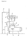
- FIG. 4 is a sectional view showing the portion of the cylindrical body 26, a heater 27 is installed on the inner side of the gable wall 6, a heat generating body 31 is built in an intersection portion of pipes in an inverse T-like shape, the cylindrical body 26 on one side is opened to the heating chamber 25 and a cylindrical body 32 on the other side is opened to the treating chamber 1. Further, a fan 34 for sucking is built in a cylindrical body 33 on the upper side of the heat generating body 31.
- the fan 34 when the fan 34 is rotated in a state in which the heat generating body 31 of, for example, a heater is operated, air sucked by the fan 34 is heated by the heat generating body 31, blown into the treating chamber 1 and also blown to the heating chamber 25.
- vaporization of fine particles of sea water in the treating chamber 1 is expedited and heating of air in the heating chamber 25 is expedited.
- heating of air in the heating chamber 25 is expedited. Further, the heating achieves power particularly when the whether is deteriorated and solar energy cannot be expected.
- the heater 27 needs not to install right under the atomizing means 13 and may be installed to shift therefrom. Further, although in the illustrated example, the heater 27 is installed in the treating chamber 1 to suck air in the treating chamber 1, it can be installed in the heating chamber 25 to suck air in the heating chamber 25. Further, there can be constructed a structure in which the heater 27 is installed outside of the outer wall 5a or 5b or the gable wall 6 or 7, sucks outer air to heat it and warm air is supplied to the treating chamber 1 or the heating chamber 25.
- the heat source is not limited to electricity but can be provided by combusting heavy oil.
- the preheating unit 12 is a device for heating sea water in a vessel at about 40 through 60 °C to a degree by which minerals in sea water are not alterated and side walls of the preheating unit 12 emits extra heat to thereby heat inside of the heating chamber 25.
- Heated sea water is supplied to the atomizing means 13 of a blowing type by a pipe 16.
- the fan 20 of the atomizing means 13 of a blowing type is rotated, warm air in the heating chamber 25 is blown into the treating chamber 1 and therefore, evaporation of moisture in fine mist of sea water is further expedited. Further, salt component and minerals remaining after vaporizing moisture are crystallized to pile up or to be stored at inside of the treating chamber 1.
- warm wind is supplied into the treating chamber 1 also from the cylindrical body 32 of the heater 27 installed on the lower side of the atomizing means 13 of a blowing type and accordingly, the inside of the treating chamber 1 is heated to about 40 through 60 °C to a degree by which substances in sea water are not alterated. As a result, vaporization and crystallization of sea water in the treating chamber is carried out smoothly.
- each of the outer roof 4 and the roof 2 of the treating chamber is suitable to be constituted by a transparent body, for example, transparent synthetic resin plate or sheet such that heat of solar ray can also be utilized in fair weather.
- the respective side walls are preferably constituted by material of light transmitting performance.
- Fig. 1 when the pump P1 is started in a state in which sea water is normally stored in the sea water tank T1, only the opening/closing valve V1 is opened and other opening/closing valves V2 and V3 are closed, sea water scooped up from the sea water tank T1 is sprinkled from the sprinkling pipe 8 on the outer roof 4 and successively flows down to the recovering grooves 10c and 10a via the side walls 5a and 5b. During the time period, the water component is evaporated by solar heat or natural wind and salt concentration of sea water is increased.
- sea water flows in an order of the recovering grooves 10a ⁇ 10b ⁇ 10c ⁇ guide groove 10e and is stored in the condensed sea water tank T2.
- Sea water condensed in this way is transmitted from the tank T2 to the preheating unit 12 by the pipe 11 and is supplied to the atomizing means 13 by the pipe 16 in a state in which sea water is accompanied by thermal energy by being heated to about 40 through 60 °C.
- Sea water is atomized by a centrifugal force by the atomizing means 13 and is scattered to a wide space in the treating chamber 1 by a wind force by the fan 20.
- Sea water supplied to the atomizing means 13 is heated in the preheating unit 12 and therefore, vaporization of the water component in the treating chamber 1 can easily be carried out.
- the heating chamber 25 is provided and air heated by extra heat produced from the preheating unit 12 is blown into the treating chamber 1 by the fan 20 and accordingly, vaporization of fine mist of sea water in the treating chamber is expedited also by the warm wind.
- warm wind is blown into the treating chamber 1 also by the heater 27 on the lower side of the atomizing means 13 and therefore, vaporization of sea water is expedited also by the warm wind.
- sea water is efficiently vaporized, the water component is recovered as fresh water and remaining salt component is utilized as natural salt.
- Condensation of salt component by sprinkling sea water on the outer roof 4 may be carried out twice or more. That is, when the second pump P2 is started in a state in which the first opening/closing valve V1 is closed and the second opening/closing valve V2 is opened, sea water in the condensed sea water tank T2 is supplied to the sprinkling pipe 8 and is again sprinkled on the outer roof 4.
- sea water having high salt concentration is produced.
- production of natural salt by vaporizing water in the treating chamber 1 is made further efficient.
- Fig. 5(1) is basically the same as the embodiment illustrated by Fig. 1 and Fig. 2
- guides 28 in a semi-circular cylinder shape are installed such that sea water sprinkled on the outer roof 4 is prevented from flowing on the outer sides of the side walls 5a and 5b by inertia as shown by arrow marks, sea water which has flowed from above the outer roof 4 is turned to the sides of the side walls 5a and 5b by which sea water flows down along the side walls 5a and 5b and enters the recovering grooves 10c and 10a.
- the guides 28 in a semi-circular cylinder shape are not installed but curved faces 29 are constituted between the outer roof 4 and the side walls 5a and 5b by which sea water which has flowed down from the outer roof 4 is guided by the side walls 5a and 5b along the curved faces 29.
- a vapor guide 30 in a V-like shape is installed right under the ridge portion of the outer roof 4 and vapor rising from the opening 22 installed at the ridge portion of the roof 2 of the treating chamber is guided by the vapor guide 30 to smoothly move into the spaces 23a and 23b of the interval D1 as shown by arrow marks.
- vapor separated from salt component flows out from a number of gaps of the louver-like roof 2a smoothly into the spaces 23a and 23b.
- sea water which has flowed down from the outer roof 4 is firmly brought into contact with the side walls 5a and 5b by which evaporation of water component is expedited and the salt concentration of sea water is increased.
- the atomizing means 13 can be installed on a wall portion other than the gable wall.
- the atomizing means 13 is not necessarily installed only on the wall portion but when a spraying structure having a constitution capable of spraying in all direction of 360° is adopted, it can also be installed at the center of the treating chamber 1. In sum, it can pertinently be selected in accordance with capacity, structure and shape of the treating chamber. Further, other than the atomizing means 13 on the side of the heating chamber 25, an exclusive machine for blowing warm air of the heating chamber 25 to the treating chamber 1 can also be installed.
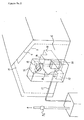
- Figs. 6(1), 6(2) and 6(3) show other embodiments of inner constitutions of the treating chamber 1.
- a net 35 in a recess shape is installed on the lower side of the duct hole 22 at the top end of the roof 2 of the treating chamber, the net 35 may be installed horizontally in the midst of the conduct hole 22.
- Fig. 7 When the embodiment is viewed by a perspective view, it is as shown by Fig. 7 .
- the net 35 is installed on the lower side of the duct hole 22 for exhausting vapor which is opened at the top end of the roof 2 in a shape of a gable roof of the treating chamber 1 and therefore, salt component separated from water component in the treating chamber or condensed sea water can be prevented from passing through the duct hole 22 without stopping.
- salt component or condensed sea water is hampered by the net 35 and is adhered to the net 35 and a sprinkling pipe 36 of sea water is arranged such that salt component or condensed sea water adhered to the net 35 is washed off and dropped into the treating chamber 1.
- the sprinkling pipe 36 is provided with a structure in which a number of holes are perforated only on the lower side and sea water is sprinkled toward the net 35.
- a net 35a extended over a wide face is stretched and side nets 35b hang from vicinities of the both ends of the net 35a.
- the side nets 35b are arranged on the inner side of the side walls 3a and 3b.
- a sprinkling pipe 36a of sea water is arranged in directions the same as those of slopes of the roof. It is preferable to install a number of the sprinkling pipes 36a in a direction orthogonal to paper face. A number of sprinkling holes are perforated on the lower side of each of the sprinkling pipes 36a and therefore, sea water can be sprayed on a wide region of the net 35a and salt component or condensed sea water adhered to the net 35a can be washed off.
- salt component or condensed sea water adhered to the side nets 35b can be washed off by sea water having high concentration which flows down from the net 35a on the ceiling side, sea water may be sprinkled from outer sides of the side nets 35b.
- the net 35a on the ceiling side of the treating chamber and the side nets 35b on the inner sides of the side walls 3a and 3b are installed, sprinkling pipes of sea water are arranged in a direction orthogonal to paper face as designated by notation 36b. Further, a plurality of them are arranged at intervals in directions the same as slopes of the roof.
- the nets 35, 35a and 35b for hampering salt component or condensed sea water from passing therethrough are provided with, for example, a mesh of about 1 mm, the invention is not limited thereto. Further, when a plurality of nets overlap as mentioned above, the mesh is made finer. Although an explanation has been given of a method of washing off salt component or condensed sea water adhered to the nets 35, 35a and 35b by sprinkling sea water in order to recover it by dropping it, it may be dropped by other method such as applying vibration.
- numeral 37 designates cloth which may be arranged on the upper side and the outer side of the wide nets 35a and 35b as shown by Fig. 6(2) or may be arranged on the lower side and the inner side of the nets 35a and 35b as shown by Fig. 6(3) . Further, as shown by Fig. 6(1) , only the cloth 37 may be stretched without using the nets 35a and 35b or the cloth 37 may be stretched doubly or triply by overlapping it or at intervals. Further, arbitrary supporting means can naturally be utilized such that the cloth is not hung.
- Numeral 38 designates a string and when a number of them are made to hang by utilizing arbitrary supporting means in the treating chamber 1, salt component is firstly adhered onto the number of strings 38 and the crystallization is expedited. When they are knocked or shaken after being adhered with a large amount of salt crystal, crystal of salt can easily be recovered.
- the cloth 37 may be constituted by woven or nonwoven cloth and material of the cloth 37 or the string 38 is arbitrary.
- salt crystal may not be provided but condensed sea water including salt crystal may be constituted. In such a case, when condensed sea water including salt stored in the treating chamber 1 is collected and condensed, only salt crystal is provided.
- condensed sea water having a sufficient concentration or condensed sea water including salt cannot be provided by carrying out atomization of sea water and evaporation of water component only once, it can be gradually condensed by circulating at plural times as in supplying condensed sea water stored in the treating chamber 1 again to the atomizing means 13 to scatter.
- the surface area in contrast to the volume is increased and vaporization of the water component is facilitated.
- separation of the water component from crystals of the salt component can efficiently be carried out.
- the warm air is blown thereto and accordingly, vaporization of the water component can further be expedited by thermal energy and wind and natural salt can inexpensively be produced.
- the treating chamber and the outflow portion for the evaporated water component there is arranged at least one of net and cloth in one stage or a plurality of stages and accordingly, when the evaporated water component passes through at least one of net and cloth, the salt component is prevented from passing therethrough and is adhered to at least one of the net and the cloth.
- the salt component separated from the water component with effort and the condensed sea water from being discharged wastefully. Further, the salt component and the condensed sea water are hampered by at least one of the net and the cloth to thereby suppress their discharges, so that an amount of the salt component contained in the discharged water component is reduced and accordingly, water obtained becomes more resembled to fresh water.
- the salt component floating in the vicinity of a side wall of the treating chamber is adhered to the net and the cloth, so that salt is produced more efficiently by dropping the adhered salt component.
- crystals of the salt component can be provided before reaching the net or the cloth and by knocking, shaking the number of strings or knocking or shaking them by collecting them at one place, the salt component can easily be collected to one place.
- the salt component or the condensed sea water adhered to the net or the cloth by being prevented from passing therethrough can be recovered at inside of the treating chamber by washing off or shaking off it by spraying sea water and accordingly, the salt component or the condensed sea water separated from the water component after all the procedure can be recovered to utilize in salt production and the salt production can be carried out efficiently.
- the sea water becomes very fine particles and moreover a large amount of sea water can be made into fine particles, so that salt and fresh water can be produced in large amount.
- the sixth aspect of the invention by adopting a method in which sea water is scattered and warm wind is blown thereto in the space of the treating chamber and evaporated water component is discharged outside of the treating chamber, large amounts of fresh water and natural salt can be separated from each other and therefore, mass production of natural salt and fresh water can be carried out further easily. As a result, natural salt and fresh water can inexpensively be supplied.
- sea water is heated at a temperature to a degree by which components in sea water are not alterated and therefore, the quality of natural salt is not deteriorated.
- one stage or plural stages of at least one of the net and the cloth for preventing the salt component from escaping are arranged between the treating chamber and the outflow portion for the evaporated water component and accordingly, in carrying out salt production by treating sea water, the salt component or the condensed sea water is hampered by the net or the cloth and the discharge is restrained and accordingly, only the water component passes through the net or the cloth and is discharged.
- the ninth aspect owing to the constitution in which a number of strings are made to hang below the net or the cloth for preventing the salt component from passing therethrough, floating salt component adheres to the number of strings before the salt component reaches the net or the cloth and accordingly, recovery of the salt component is easy which is suitable for mass production.
- the salt component or the condensed sea water adhered to the net or the cloth is washed off by spraying sea water on the net or the cloth, the salt component or the condensed sea water adhered to the net or the cloth can be recovered to use for salt production.
- the salt component or the condensed sea water can be prevented from being discharged wastefully and the yield of salt production is promoted.
- sea water can be atomized in the treating chamber and can be scattered in a wide space to facilitate vaporization of the water component.
- thermal energy and wind can be provided to small particles of sea water. Vaporized vapor rises owing to the light specific weight and a duct hole for discharge is opened at the roof portion of the treating chamber and accordingly, only water component can be smoothly discharged from the treating chamber and can be separated from crystals of natural salt.
- the net is provided so as to cover the duct of the roof portion for discharging the water vapor vaporized in the treating chamber, and means for dropping the salt component adhered to the net is provided and accordingly, it is possible to drop the salt component adhered to the net and the condensed sea water by such means as washing off with the sea water, so that it is suitable for efficiently producing salt in mass-production basis.
- the net or the cloth for adhering the salt component is arranged in a midway or on a lower side of a duct hole opened between the inside of the treating chamber and the outside of the treating chamber, even the net or the cloth having a comparatively small area is sufficient and means for washing off the salt component or the condensed sea water adhered to the net or the cloth is sufficient with a small scale. Further, all of the salt component or the condensed sea water discharged from the inside of the treating chamber to the outside passes through the duct hole and accordingly, the salt component or the condensed sea water can be recovered efficiently.
- sea water is scattered on the outer roof, the water component is evaporated by solar ray and wind, the concentration of the salt component is increased and thereafter, sea water is supplied to the atomizing means, very fine mist of sea water is produced in the treating chamber and accordingly, separation of the water component from the salt component can efficiently be carried out.
- the space constitutes negative pressure.
- thermal energy absorbed in the treating chamber as vaporization heat is discharged as liquefaction heat.
- the discharge heat can expedite condensation by warming sea water scattered on the outer roof and can contribute to vaporization of small particles of sea water by being transferred also into the treating chamber.
- the net or the cloth for adhering the salt component is arranged on the lower side of the inner roof of the treating chamber or on the inside of the side wall, the net or the cloth can be stretched in a wide region, the salt component or the condensed sea water is caught in a wide area and accordingly, the efficiency of recovering the salt component or the condensed sea water is increased.
- the salt component adhered to the number of strings before reaching the net or the cloth and accordingly, the salt component adhered to the strings can be shaken off and the recovery of the salt component is facilitated which is suitable for mass production.
- the sixteenth aspect of the invention owing to the constitution in which sea water is scattered from the upper side of the net on the lower side of the inner roof and the salt component is washed off and accordingly, a large amount of the salt component or the condensed sea water adhered to the net or the cloth in a wide region can efficiently be recovered and can be utilized in salt production.
- the preheating unit of sea water before supplying sea water to the atomizing means, the preheating unit of sea water is provided, sea water accompanied by thermal energy is supplied to the atomizing means and therefore, vaporization of water component of fine mist of sea water is further expedited.
- the heating chamber is installed at a distance from the side wall of the treating chamber, warm air in the heating chamber is blown to the inside of the treating chamber and therefore, a large amount of thermal energy can be provided to very fine mist of sea water in the treating chamber and vaporization of the water component is further expedited.
- the preheating unit of sea water in accordance with the seventeenth aspect of the invention is provided in the heating chamber and extra heat produced from the preheating unit of sea water is utilized and accordingly, the constitution is economical.
- thermo energy is provided to very small particles of sea water in the treating chamber and the water component and the salt component can smoothly be separated from each other.
- the water distributing structure capable of supplying sea water to the preheating unit without via the outer roof, when the processing of condensing sea water by natural energy cannot be carried out on the outer roof due to rainy weather, sea water is supplied as it is to the preheating unit, thermal energy is provided to sea water and sea water can be supplied to the treating chamber and accordingly, natural salt and fresh water can be produced without being controlled by weather.
- the sea water can be condensed by natural energy on the outer roof over a plurality of times. Accordingly, the structure is suitable for the case of mass production of natural salt.
- the twenty-second aspect of the invention by constituting the outer roof and the roof of the treating chamber by transparent bodies, solar energy can reach the inside of the treating chamber to thereby heat it and accordingly, in fine weather, vaporization of fine mist of sea water in the treating chamber can efficiently be carried out.
Landscapes
- Chemical & Material Sciences (AREA)
- Organic Chemistry (AREA)
- Engineering & Computer Science (AREA)
- Chemical Kinetics & Catalysis (AREA)
- Life Sciences & Earth Sciences (AREA)
- Water Supply & Treatment (AREA)
- Environmental & Geological Engineering (AREA)
- Hydrology & Water Resources (AREA)
- Inorganic Chemistry (AREA)
- Materials Engineering (AREA)
- Thermal Sciences (AREA)
- Physics & Mathematics (AREA)
- Heat Treatment Of Water, Waste Water Or Sewage (AREA)
- Vaporization, Distillation, Condensation, Sublimation, And Cold Traps (AREA)
Claims (21)
- Verfahren zur Behandlung von Meerwasser zum Herstellen von Salz durch Zerstäuben (13) von Meerwasser durch Rotierenlassen eines Fliehkraftgenerators (14, 15; 19) und Verdampfen (12, 20, 25, 27, 31, 34) einer Wasserkomponente zum Auskristallisierenlassen des Salzes durch Anblasen mit Warmluft, wobei zwischen einer Behandlungskammer (1) und einem Ausflußabschnitt (22, 23a, 23b) für die verdampfte Wasserkomponente mindestens eines von einem Netz (35; 35a, 35b) und einem Tuch (37) in einer Stufe oder mehreren Stufen angeordnet ist, wobei die Salzkomponente beim Hindurchlaufen der verdampften Wasserkomponente durch mindestens eines von dem Netz und dem Tuch an mindestens einem von dem Netz und dem Tuch haftenbleibt und danach die anhaftende Salzkomponente von mindestens einem von dem Netz und dem Tuch abfällt.
- Verfahren zur Behandlung von Meerwasser nach Anspruch 1, wobei mindestens eines von dem Netz (35b) und dem Tuch (37) an dem seitlichen Abschnitt der Behandlungskammer (1) aufgehängt ist und die Salzkomponente an diesem haftet.
- Verfahren zur Behandlung von Meerwasser nach Anspruch 2, wobei an einer Unterseite von mindestens einem von dem Netz (35a) und dem Tuch (37) eine Anzahl von Schnüren (38) aufgehängt ist und die Salzkomponente an der Anzahl von Schnüren (38) haftet.
- Verfahren zum Behandeln von Meerwasser nach Anspruch 2 oder 3, wobei die an mindestens einem von dem Netz (35; 35a, 35b) und dem Tuch (37) haftende Salzkomponente durch Abwaschen der Salzkomponente mit Meerwasser oder durch ein anderes Verfahren gewonnen wird.
- Verfahren zur Behandlung von Meerwasser nach einem der Ansprüche 1 bis 4, wobei das Zerstäuben des Meerwassers durch Rotierenlassen eines Fliehkraftgenerators durch Ausübung einer Zentrifugalkraft auf das Meerwasser durch Rotierenlassen eines Flügelrads erfolgt, in dem gebogene Schaufeln (19) in Radialrichtung in einem Raum zwischen zwei runden Scheiben (17, 18) vorgesehen sind, und das in seiner Mitte eine Wassereinspritzöffnung (16) aufweist.
- Verfahren zur Behandlung von Meerwasser nach Anspruch 1 oder 2, wobei das Zerstäuben des Meerwassers durch das Verteilen (13) des Meerwassers in der Behandlungskammer (1) durch Rotierenlassen des Fliehkraftgenerators (14, 15; 19) erfolgt, die Warmluft eingeblasen wird, die verdampfte Komponente aus der Behandlungskammer (1) heraus abgeführt und in der Behandlungskammer (1) eine auskristallisierte Salzkomponente gespeichert wird.
- Verfahren zum Behandeln von Meerwasser nach einem der Ansprüche 1 bis 6, wobei das Meerwasser zerstäubt wird, nachdem das Meerwasser auf eine Temperatur bis zu einem Grad vorgewärmt wurde, bis zu welchem sich die Komponenten in dem Meerwasser nicht verändern.
- Vorrichtung zum Behandeln von Meerwasser zur Herstellung von Salz, mit:einem Mittel zum Zerstäuben (13) von Meerwasser durch Rotierenlassen eines Fliehkraftgenerators (14, 15; 19) undWarmluftblasmitteln (12, 20, 25, 27, 31, 34) zum Blasen von Warmluft zu Nebeln des atomisierten Meerwassers (21),wobei zwischen einer Behandlungskammer (1) und einem Ausflußabschnitt (22, 23a, 23b) für die verdampfte Wasserkomponente mindestens eines von einem Netz (35; 35a, 35b) und einem Tuch (37) in einer Stufe oder mehreren Stufen angeordnet ist und ein Mittel zum Abfallenlassen (36; 36a; 36b) der an mindestens einem von dem Netz (35; 35a, 35b) und dem Tuch (37) haftenden Salzkomponente von mindestens einem von dem Netz (35; 35a, 35b) und dem Tuch (37) vorgesehen ist.
- Vorrichtung zum Behandeln von Meerwasser nach Anspruch 8, mit:einem Mittel zum Verteilen (13) des Meerwassers in der Behandlungskammer (1),wobei an einem Dachabschnitt (2) der Behandlungskammer (1) eine Kanalöffnung (22) zum Ablassen von in der Behandlungskammer (1) verdampftem Wasserdampf aus der Behandlungskammer nach außen vorgesehen ist und
wobei mindestens eines von dem Netz (35) und dem Tuch so vorgesehen ist, daß es die Kanalöffnung (22) abdeckt. - Vorrichtung zum Behandeln von Meerwasser nach Anspruch 8 oder Anspruch 9, wobei an einer Unterseite von mindestens einem von dem Netz (35a) und dem Tuch (37) eine Anzahl von Schnüren (38) aufgehängt ist, um die Salzkomponente anhaften zu lassen.
- Vorrichtung zum Behandeln von Meerwasser nach einem der Ansprüche 8 bis 10, wobei das Mittel zum Abwaschen (36; 36a; 36b) der Salzkomponente durch Versprühen des Meerwassers auf mindestens einem von dem Netz (35; 35a, 35b) und dem Tuch (37) auf einer Oberseite von mindestens einem von dem Netz (35; 35a, 35b) und dem Tuch (37) angeordnet ist.
- Vorrichtung zum Behandeln von Meerwasser nach Anspruch 11, wobei das Mittel zum Abwaschen (36a; 36b) der Salzkomponente auch auf der Unterseite des Dachabschnitts (2) der Behandlungskammer (1) angeordnet ist.
- Vorrichtung zum Behandeln von Meerwasser nach einem der Ansprüche 11 bis 12, wobei mindestens eine Stufe von mindestens einem von einem Netz (35; 35a, 35b) und einem Tuch (37) zum Anhaftenlassen einer Salzkomponente auf halbem Wege zu der Kanalöffnung (22) oder auf einer Unterseite derselben angeordnet ist.
- Vorrichtung zum Behandeln von Meerwasser nach einem der Ansprüche 9 bis 13, wobei über dem Dachabschnitt (2) der Behandlungskammer (1) ein äußeres Dach (4) vorgesehen ist und an der Außenseite der Seitenwände (3a, 3b) der Behandlungskammer (1) eine Außenwand (5a, 5b) angeordnet ist,
wobei über dem äußeren Dach (4) ein Mittel zum Verteilen des Meerwassers vorgesehen ist und
wobei eine Wasserverteilungskonstruktion gebildet ist, in der das von dem äußeren Dach (4) rückgewonnene Meerwasser zu dem Mittel (13) zum Zerstäuben geführt wird. - Vorrichtung zum Behandeln von Meerwasser nach einem der Ansprüche 9 bis 14, wobei mindestens eine Stufe von mindestens einem von dem Netz (35; 35a, 35b) und dem Tuch (37) zum Anhaftenlassen der Salzkomponente an mindestens einer von einer Unterseite des Dachabschnitts (2) der Behandlungskammer (1) (dem inneren Dach) und den Innenseiten der Seitenwände (3a, 3b) angeordnet ist.
- Vorrichtung zum Behandeln von Meerwasser nach einem der Ansprüche 9 bis 15, ferner umfassend:eine Vorwärmeinheit (12) zum Aufheizen des dem Mittel zum Zerstäuben (13) des Meerwassers zugeführten Meerwassers auf eine Temperatur bis in einem Grad, bis zu dem sich die Komponenten in dem Meerwasser nicht verändern.
- Vorrichtung zum Behandeln von Meerwasser nach einem der Ansprüche 9 bis 16, wobei in einem Abstand von der Seitenwand (3a, 3b) der Behandlungskammer (1) eine Heizkammer (25) eingebaut ist,
wobei das Meerwasseraufheizmittel (12) in der Heizkammer (25) eingebaut ist und
wobei in der Heizkammer (25) aufgeheizte Luft durch Blasmittel (20, 34) aus einer Öffnung, die an der Seitenwand geöffnet ist, in die Behandlungskammer (1) eingeblasen wird. - Vorrichtung zum Behandeln von Meerwasser nach einem der Ansprüche 9 bis 17, ferner umfassend:eine Heizeinrichtung (27) zum Einführen von Warmluft in die Behandlungskammer (1).
- Vorrichtung zum Behandeln von Meerwasser nach einem der Ansprüche 14 bis 18, wobei eine Wasserverteilungskonstruktion gebildet ist, die das Meerwasser über das äußere Dach (4) zu der Aufheizeinheit führen kann.
- Vorrichtung zum Behandeln von Meerwasser nach einem der Ansprüche 14 bis 19, wobei eine Wasserverteilungskonstruktion zum Verteilen des Meerwassers in einem Meerwassertank (T1, T2) zum Speichern des Meerwassers durch Rückgewinnung des auf dem äußeren Dach (4) verteilten Meerwassers, Führen und erneuten Verteilen des Meerwassers auf dem äußeren Dach (4) gebildet ist.
- Vorrichtung zum Behandeln von Meerwasser nach einem der Ansprüche 14 bis 20, wobei mindestens das Dach (2) der Behandlungskammer (1) und das äußere Dach (4) durchsichtige Körper umfassen.
Applications Claiming Priority (5)
| Application Number | Priority Date | Filing Date | Title |
|---|---|---|---|
| JP5091697 | 1997-02-18 | ||
| JP5091697 | 1997-02-18 | ||
| JP30939297 | 1997-10-22 | ||
| JP30939297 | 1997-10-22 | ||
| PCT/JP1998/000651 WO1998035911A1 (en) | 1997-02-18 | 1998-02-16 | Method and apparatus for desalinating sea water, natural salt and fresh water |
Publications (3)
| Publication Number | Publication Date |
|---|---|
| EP0985637A1 EP0985637A1 (de) | 2000-03-15 |
| EP0985637A4 EP0985637A4 (de) | 2005-10-12 |
| EP0985637B1 true EP0985637B1 (de) | 2008-10-29 |
Family
ID=26391403
Family Applications (1)
| Application Number | Title | Priority Date | Filing Date |
|---|---|---|---|
| EP98902261A Expired - Lifetime EP0985637B1 (de) | 1997-02-18 | 1998-02-16 | Methode und vorrichtung zur entsalzung von meerwasser, natürliches salz und süsswasser |
Country Status (11)
| Country | Link |
|---|---|
| US (1) | US6500216B1 (de) |
| EP (1) | EP0985637B1 (de) |
| JP (1) | JP3250738B2 (de) |
| KR (1) | KR100352820B1 (de) |
| CN (1) | CN1138702C (de) |
| AU (1) | AU736603B2 (de) |
| BR (1) | BR9807411A (de) |
| CA (1) | CA2279884C (de) |
| DE (1) | DE69840167D1 (de) |
| NZ (1) | NZ336401A (de) |
| WO (1) | WO1998035911A1 (de) |
Families Citing this family (70)
| Publication number | Priority date | Publication date | Assignee | Title |
|---|---|---|---|---|
| IL130357A0 (en) * | 1999-06-08 | 2000-06-01 | Kedem Avraham | Evaporation device |
| KR20010027135A (ko) * | 1999-09-10 | 2001-04-06 | 김남경 | 천일염 제조방법 및 그 설비 |
| US6649027B1 (en) * | 2000-03-07 | 2003-11-18 | Honeywell International Inc. | Water reclamation system |
| KR20010096679A (ko) * | 2001-07-12 | 2001-11-08 | 김선회 | 해수를 이용한 소금 제조장치 |
| KR20030012055A (ko) * | 2001-07-30 | 2003-02-12 | 이영남 | 소금 제조 방법 및 그를 위한 장치 |
| FR2847571B1 (fr) * | 2002-11-22 | 2005-09-30 | Marcel Siragna | Dessalement de l'eau de mer par un procede geothermique |
| US20040141810A1 (en) * | 2003-01-17 | 2004-07-22 | Clark Lysne | Soil desalinator |
| KR100543574B1 (ko) * | 2003-11-05 | 2006-01-20 | 주식회사 대한심층수 | 미네랄 조성물 및 그 제조방법 |
| US20060124440A1 (en) * | 2004-12-13 | 2006-06-15 | Pautz Richard S | Method and apparatus to produce potable water |
| CN100362083C (zh) * | 2005-03-03 | 2008-01-16 | 乌鲁木齐金穗剑技术开发有限公司 | 炼油碱洗残液碱渣雾化风干处理技术 |
| EP1899043A4 (de) * | 2005-07-05 | 2011-03-23 | Greensols Australia Pty Ltd | Herstellung und verwendung von kationischen halogeniden, sequestrierung von kohlendioxid |
| US7357849B2 (en) * | 2005-09-01 | 2008-04-15 | Watervap, Llc | Method and system for separating solids from liquids |
| US20070045099A1 (en) * | 2005-09-01 | 2007-03-01 | Watervap, Llc | Method and system for seaparating solids from liquids |
| US7771567B2 (en) * | 2005-09-02 | 2010-08-10 | Rives Michael L | Salt water distillation system |
| JP2008012390A (ja) * | 2006-07-03 | 2008-01-24 | Nuchimasu:Kk | 微細霧発生器 |
| US10005678B2 (en) | 2007-03-13 | 2018-06-26 | Heartland Technology Partners Llc | Method of cleaning a compact wastewater concentrator |
| US8801897B2 (en) | 2007-03-13 | 2014-08-12 | Heartland Technology Partners Llc | Compact wastewater concentrator and contaminant scrubber |
| US8790496B2 (en) | 2007-03-13 | 2014-07-29 | Heartland Technology Partners Llc | Compact wastewater concentrator and pollutant scrubber |
| US8679291B2 (en) | 2007-03-13 | 2014-03-25 | Heartland Technology Partners Llc | Compact wastewater concentrator using waste heat |
| US8741100B2 (en) | 2007-03-13 | 2014-06-03 | Heartland Technology Partners Llc | Liquid concentrator |
| US20090173678A1 (en) * | 2008-01-03 | 2009-07-09 | Clark Emory Lysne | Vertical evaporation technologies |
| DE102009006668A1 (de) | 2009-01-29 | 2010-08-05 | Technische Universität Bergakademie Freiberg | Verfahren und Vorrichtung zur solaren Eindampfung von Salzlösungen |
| WO2010093958A2 (en) | 2009-02-12 | 2010-08-19 | Heartland Technology Partners Llc | Compact wastewater concentrator using waste heat |
| KR101018422B1 (ko) * | 2009-04-09 | 2011-02-28 | 김현미 | 하우스형 결정지와 이를 이용한 소금의 제조방법 |
| US20110086250A1 (en) * | 2009-04-16 | 2011-04-14 | Macdonald R Ian | Method and apparatus for storing electrical power by evaporating water |
| US20110204841A9 (en) * | 2009-04-16 | 2011-08-25 | Macdonald R Ian | System for storing electrical energy |
| IL199570A0 (en) | 2009-06-25 | 2010-04-29 | Lesico Technologies Ltd | Evaporation assembly and evaporation element |
| EP2455343A1 (de) * | 2009-07-13 | 2012-05-23 | Electra Holdings Co., Ltd. | Wasserreinigungsvorrichtung |
| IL202169B (en) | 2009-11-16 | 2018-08-30 | Gilron Jack | Evaporative element |
| US8273165B2 (en) | 2009-12-11 | 2012-09-25 | Micronic Technologies, LLC | Compacted air flow rapid fluid evaporation system |
| US9044692B2 (en) * | 2009-12-11 | 2015-06-02 | Micronic Technologies, Inc. | Systems and methods for water desalinization |
| CN101804997A (zh) * | 2010-03-12 | 2010-08-18 | 王琨彭 | 一种利用太阳能风能提高晒盐产量的装置及其应用 |
| TWM392171U (en) * | 2010-06-30 | 2010-11-11 | Yeu Ming Tai Chemical Ind Co Ltd | Desalination device |
| KR101367764B1 (ko) * | 2010-11-24 | 2014-02-26 | 서울과학기술대학교 산학협력단 | 풍력터빈을 이용한 담수 생산 장치 |
| WO2012100074A2 (en) | 2011-01-21 | 2012-07-26 | Heartland Technology Partners Llc | Condensation plume mitigation system for exhaust stacks |
| ES2353301B2 (es) * | 2011-01-31 | 2011-07-05 | Tografa S.L. | Balsa para la obtención de sal y procedimiento por evaporación forzada de agua en soluciones salinas. |
| ES2401516B1 (es) * | 2011-03-22 | 2014-03-27 | Universitat Politècnica De Catalunya | Planta desalinizadora solar de agua de mar, salmueras o aguas residuales. |
| KR20130023774A (ko) * | 2011-08-30 | 2013-03-08 | 김병곤 | 스크린(Screen)을 이용한 소금 생산 방법 |
| KR20130025504A (ko) * | 2011-09-02 | 2013-03-12 | 김병곤 | 태양열에 의한 미네랄 정제염 제조 장치 |
| CN102358628B (zh) * | 2011-09-16 | 2015-02-04 | 北京运特科技有限公司 | 低能耗压力喷雾脱盐装置及方法 |
| US9296624B2 (en) | 2011-10-11 | 2016-03-29 | Heartland Technology Partners Llc | Portable compact wastewater concentrator |
| US20130192131A1 (en) * | 2012-01-26 | 2013-08-01 | Mansur Abahusayn | Desalination greenhouse |
| WO2013116465A1 (en) | 2012-02-01 | 2013-08-08 | Micronic Technologies, Inc. | Systems and methods for water purification |
| US8808497B2 (en) | 2012-03-23 | 2014-08-19 | Heartland Technology Partners Llc | Fluid evaporator for an open fluid reservoir |
| US8741101B2 (en) | 2012-07-13 | 2014-06-03 | Heartland Technology Partners Llc | Liquid concentrator |
| US8623174B1 (en) | 2012-12-14 | 2014-01-07 | Heartland Technology Partners Llc | Liquid evaporation system with heated liquid |
| US9199861B2 (en) | 2013-02-07 | 2015-12-01 | Heartland Technology Partners Llc | Wastewater processing systems for power plants and other industrial sources |
| US8585869B1 (en) | 2013-02-07 | 2013-11-19 | Heartland Technology Partners Llc | Multi-stage wastewater treatment system |
| KR101420566B1 (ko) * | 2013-03-20 | 2014-08-13 | 김진호 | 소금 제조장치 |
| CN103332707B (zh) * | 2013-07-16 | 2015-04-29 | 王家兵 | 一种利用太阳能制备高产生态盐的工艺 |
| KR101569574B1 (ko) | 2013-10-21 | 2015-11-16 | 정인영 | 수분 증발 가속기 |
| CN103553087B (zh) * | 2013-11-15 | 2015-06-17 | 中国科学院青海盐湖研究所 | 利用自然能从混合卤水中制备硫酸锂盐矿的方法 |
| CN103553088B (zh) * | 2013-11-15 | 2015-06-17 | 中国科学院青海盐湖研究所 | 利用自然能从混合卤水中制备锂硼盐矿的方法 |
| CN103539161B (zh) * | 2013-11-15 | 2015-05-20 | 中国科学院青海盐湖研究所 | 利用自然能从混合卤水中制备钾石盐矿的方法 |
| GR20170100103A (el) * | 2017-03-14 | 2018-10-31 | Ιωαννης Δημητριου Μπατσης | Μεθοδος επιταχυνσης της εξατμισης υδατων |
| CN108862441B (zh) * | 2017-05-11 | 2021-07-20 | 中国石油化工股份有限公司 | 高含盐量油气田采出水的处理系统 |
| US10233095B1 (en) * | 2018-02-20 | 2019-03-19 | King Saud University | Solar desalination and power generating system |
| US10183233B1 (en) * | 2018-02-20 | 2019-01-22 | King Saud University | Solar desalination system |
| CN110844954A (zh) * | 2018-08-21 | 2020-02-28 | 国家能源投资集团有限责任公司 | 蒸发系统 |
| WO2020081640A1 (en) * | 2018-10-17 | 2020-04-23 | Northwestern University | Brine management system for achieving zero liquid discharge |
| EP3914369A4 (de) * | 2019-01-25 | 2022-10-26 | Copping Refuse Disposal Site Joint Authority | Verdampfungseinheit und system |
| CN109970123B (zh) * | 2019-02-21 | 2021-07-23 | 山东格瑞水务有限公司 | 一种含盐污水的处理装置 |
| US20200376406A1 (en) | 2019-05-31 | 2020-12-03 | Heartland Technology Partners Llc. | Harmful substance removal system and method |
| CN110467234B (zh) * | 2019-09-18 | 2024-01-26 | 内蒙古尖锋科技有限公司 | 便携式光伏直接蒸馏法淡化水装置 |
| EP3885017A1 (de) * | 2020-03-26 | 2021-09-29 | Groasis IP B.V. | Wasserdestillationsgerät |
| US11345612B2 (en) | 2020-07-10 | 2022-05-31 | Darian Petrisca | Solar powered water desalinator and method |
| US11597660B2 (en) | 2021-02-22 | 2023-03-07 | Saudi Arabian Oil Company | Control of hot air flow circulation within a solar desalination system |
| US11554970B2 (en) | 2021-02-22 | 2023-01-17 | Saudi Arabian Oil Company | Hot air flow-circulation within a solar desalination system |
| KR102389951B1 (ko) * | 2021-08-27 | 2022-04-22 | 박규식 | 해수 농축방법 |
| US12324993B1 (en) * | 2024-03-15 | 2025-06-10 | United Arab Emirates University | Direct solar desalination with atomized droplets and heat recovery |
Family Cites Families (23)
| Publication number | Priority date | Publication date | Assignee | Title |
|---|---|---|---|---|
| US3904122A (en) * | 1972-05-11 | 1975-09-09 | Zachry Co H B | Rotary desalting device |
| JPS5218473A (en) * | 1975-08-04 | 1977-02-12 | Toa Kogyo Kk | Evaporating apparatus |
| JPS578882Y2 (de) * | 1977-05-24 | 1982-02-20 | ||
| JPS5939363B2 (ja) * | 1978-02-24 | 1984-09-22 | 克彦 谷 | 食塩製造方法 |
| JPS5581777A (en) * | 1978-12-15 | 1980-06-20 | Kajima Corp | Solar-energy-utilizing desalter |
| JPS5634597U (de) * | 1979-08-25 | 1981-04-04 | ||
| JPS56160319A (en) * | 1980-05-03 | 1981-12-10 | Katsuhiko Tani | Salt manufacturing apparatus |
| JPS58124583A (ja) * | 1982-01-21 | 1983-07-25 | Hitachi Zosen Corp | 造水方法 |
| JPS58128181A (ja) * | 1982-01-26 | 1983-07-30 | Hitachi Zosen Corp | 造水方法 |
| IL65869A (en) * | 1982-03-12 | 1986-11-30 | Assaf Gad | Method of concentrating brine |
| DE3213084A1 (de) * | 1982-04-07 | 1983-10-20 | Herbert Hans 8900 Augsburg Wagner | Einrichtung zur gewinnung von suesswasser aus meerwasser |
| JPS6182805A (ja) * | 1984-09-27 | 1986-04-26 | Power Reactor & Nuclear Fuel Dev Corp | 液体金属ベ−パ−トラツプ |
| JPS6193885A (ja) * | 1984-10-16 | 1986-05-12 | Mitsuo Tomita | 海水淡水化装置 |
| US5015332A (en) * | 1987-07-06 | 1991-05-14 | Tdk Corporation | Spray dryer |
| DK489688D0 (da) * | 1988-09-02 | 1988-09-02 | Damrow Co Inc | Forstoevningstoerreapparat |
| IL89404A (en) * | 1989-02-24 | 1993-05-13 | Ormat Turbines 1965 Ltd | Method of and apparatus for evaporating and cooling liquid |
| JPH0328299U (de) * | 1989-07-26 | 1991-03-20 | ||
| JPH04310281A (ja) * | 1991-04-05 | 1992-11-02 | Shinwa Sangyo Kk | 太陽熱利用の塩水淡水化装置 |
| CA2086090A1 (en) * | 1991-04-26 | 1992-10-27 | Manuel Lumbreras Y Gimenez | Method and apparatus for desalination of saltwater |
| JPH05218473A (ja) * | 1992-02-03 | 1993-08-27 | Matsushita Electric Ind Co Ltd | CdS/CdTe系太陽電池用CdS膜の製造方法 |
| US5348622A (en) * | 1993-09-14 | 1994-09-20 | David Deutsch | Solar water purification device |
| CN1182406A (zh) * | 1995-02-28 | 1998-05-20 | 玉城佑春 | 制盐方法及其装置 |
| WO1998005432A1 (fr) * | 1996-08-03 | 1998-02-12 | Masakatsu Takayasu | Appareil de pulverisation et methode correspondante |
-
1998
- 1998-02-16 WO PCT/JP1998/000651 patent/WO1998035911A1/ja not_active Ceased
- 1998-02-16 CA CA002279884A patent/CA2279884C/en not_active Expired - Fee Related
- 1998-02-16 CN CNB988026376A patent/CN1138702C/zh not_active Expired - Fee Related
- 1998-02-16 JP JP53558998A patent/JP3250738B2/ja not_active Expired - Fee Related
- 1998-02-16 US US09/355,697 patent/US6500216B1/en not_active Expired - Lifetime
- 1998-02-16 BR BR9807411-3A patent/BR9807411A/pt not_active IP Right Cessation
- 1998-02-16 KR KR1019997005835A patent/KR100352820B1/ko not_active Expired - Fee Related
- 1998-02-16 NZ NZ336401A patent/NZ336401A/xx unknown
- 1998-02-16 AU AU58818/98A patent/AU736603B2/en not_active Ceased
- 1998-02-16 DE DE69840167T patent/DE69840167D1/de not_active Expired - Lifetime
- 1998-02-16 EP EP98902261A patent/EP0985637B1/de not_active Expired - Lifetime
Also Published As
| Publication number | Publication date |
|---|---|
| CA2279884A1 (en) | 1998-08-20 |
| BR9807411A (pt) | 2000-03-14 |
| JP3250738B2 (ja) | 2002-01-28 |
| AU736603B2 (en) | 2001-08-02 |
| EP0985637A1 (de) | 2000-03-15 |
| DE69840167D1 (de) | 2008-12-11 |
| NZ336401A (en) | 2000-09-29 |
| EP0985637A4 (de) | 2005-10-12 |
| KR20000069736A (ko) | 2000-11-25 |
| KR100352820B1 (ko) | 2002-09-16 |
| HK1027084A1 (en) | 2001-01-05 |
| CN1138702C (zh) | 2004-02-18 |
| CN1248227A (zh) | 2000-03-22 |
| AU5881898A (en) | 1998-09-08 |
| WO1998035911A1 (en) | 1998-08-20 |
| US6500216B1 (en) | 2002-12-31 |
| CA2279884C (en) | 2003-04-22 |
Similar Documents
| Publication | Publication Date | Title |
|---|---|---|
| CA2279884C (en) | Method and apparatus for desalinating sea water, natural salt and fresh water | |
| JPWO1998035911A1 (ja) | 海水の処理方法および処理装置、自然塩並びに淡水 | |
| US6574979B2 (en) | Production of potable water and freshwater needs for human, animal and plants from hot and humid air | |
| US7225620B2 (en) | Diffusion driven water purification apparatus and process | |
| JP7783277B2 (ja) | 大気水生成システムおよび方法 | |
| US3070969A (en) | Separation systems | |
| US20120073320A1 (en) | Atmospheric water generator | |
| JP2008531965A (ja) | 冷媒として水を使用する小型ヒートポンプ | |
| CN106422378A (zh) | 用于水净化的方法和装置 | |
| WO2018033722A1 (en) | Water or evaporative cooler comprising a woven or warp-knitted mesh sheet | |
| US11753313B2 (en) | Rapid evaporation of water for desalination and dewatering using nanobubbles and micro-droplets | |
| US12345025B2 (en) | Atmospheric water generation systems and methods | |
| JPH11207318A (ja) | 塩水蒸留温室 | |
| CN105129888A (zh) | 一种含盐废水的蒸发处理装置 | |
| KR20140132007A (ko) | 수처리 장치 | |
| KR102006326B1 (ko) | 태양열을 이용한 수 처리 장치 | |
| US3442801A (en) | Process and apparatus for separating water from an aqueous solution | |
| US20180016160A1 (en) | Eutectic freeze crystallization spray chamber | |
| KR101220864B1 (ko) | 중금속처리조를 포함한 바이오 소금과 태양열 에너지 이용 소금제조 기계장치 및 그를 이용한 소금 제조방법 | |
| JP2003210905A (ja) | 各種溶液中の溶解物の結晶化方法、結晶化装置並びに結晶化物 | |
| HK1027084B (en) | Method and apparatus for desalinating sea water | |
| JP7053218B2 (ja) | 水処理装置 | |
| RU2646640C1 (ru) | Пруд-испаритель минерализованного дренажного стока | |
| TWM581105U (zh) | 共晶冷凍結晶噴霧室 | |
| JPH0236281B2 (ja) | Tadanshikijohatsushosekisochi |
Legal Events
| Date | Code | Title | Description |
|---|---|---|---|
| PUAI | Public reference made under article 153(3) epc to a published international application that has entered the european phase |
Free format text: ORIGINAL CODE: 0009012 |
|
| 17P | Request for examination filed |
Effective date: 19990915 |
|
| AK | Designated contracting states |
Kind code of ref document: A1 Designated state(s): BE DE DK ES FR GB GR IT NL PT |
|
| A4 | Supplementary search report drawn up and despatched |
Effective date: 20050831 |
|
| RIC1 | Information provided on ipc code assigned before grant |
Ipc: 7B 01D 5/00 B Ipc: 7C 02F 1/10 B Ipc: 7C 02F 1/06 B Ipc: 7B 01D 1/16 B Ipc: 7C 02F 1/12 B Ipc: 7C 01D 3/06 A |
|
| 17Q | First examination report despatched |
Effective date: 20061006 |
|
| 17Q | First examination report despatched |
Effective date: 20061006 |
|
| GRAP | Despatch of communication of intention to grant a patent |
Free format text: ORIGINAL CODE: EPIDOSNIGR1 |
|
| GRAS | Grant fee paid |
Free format text: ORIGINAL CODE: EPIDOSNIGR3 |
|
| GRAA | (expected) grant |
Free format text: ORIGINAL CODE: 0009210 |
|
| AK | Designated contracting states |
Kind code of ref document: B1 Designated state(s): BE DE DK ES FR GB GR IT NL PT |
|
| REG | Reference to a national code |
Ref country code: GB Ref legal event code: FG4D |
|
| REF | Corresponds to: |
Ref document number: 69840167 Country of ref document: DE Date of ref document: 20081211 Kind code of ref document: P |
|
| NLV1 | Nl: lapsed or annulled due to failure to fulfill the requirements of art. 29p and 29m of the patents act | ||
| PG25 | Lapsed in a contracting state [announced via postgrant information from national office to epo] |
Ref country code: ES Free format text: LAPSE BECAUSE OF FAILURE TO SUBMIT A TRANSLATION OF THE DESCRIPTION OR TO PAY THE FEE WITHIN THE PRESCRIBED TIME-LIMIT Effective date: 20090209 |
|
| PG25 | Lapsed in a contracting state [announced via postgrant information from national office to epo] |
Ref country code: PT Free format text: LAPSE BECAUSE OF FAILURE TO SUBMIT A TRANSLATION OF THE DESCRIPTION OR TO PAY THE FEE WITHIN THE PRESCRIBED TIME-LIMIT Effective date: 20090330 Ref country code: NL Free format text: LAPSE BECAUSE OF FAILURE TO SUBMIT A TRANSLATION OF THE DESCRIPTION OR TO PAY THE FEE WITHIN THE PRESCRIBED TIME-LIMIT Effective date: 20081029 |
|
| PG25 | Lapsed in a contracting state [announced via postgrant information from national office to epo] |
Ref country code: DK Free format text: LAPSE BECAUSE OF FAILURE TO SUBMIT A TRANSLATION OF THE DESCRIPTION OR TO PAY THE FEE WITHIN THE PRESCRIBED TIME-LIMIT Effective date: 20081029 Ref country code: BE Free format text: LAPSE BECAUSE OF FAILURE TO SUBMIT A TRANSLATION OF THE DESCRIPTION OR TO PAY THE FEE WITHIN THE PRESCRIBED TIME-LIMIT Effective date: 20081029 |
|
| PG25 | Lapsed in a contracting state [announced via postgrant information from national office to epo] |
Ref country code: IT Free format text: LAPSE BECAUSE OF FAILURE TO SUBMIT A TRANSLATION OF THE DESCRIPTION OR TO PAY THE FEE WITHIN THE PRESCRIBED TIME-LIMIT Effective date: 20081029 |
|
| PLBE | No opposition filed within time limit |
Free format text: ORIGINAL CODE: 0009261 |
|
| STAA | Information on the status of an ep patent application or granted ep patent |
Free format text: STATUS: NO OPPOSITION FILED WITHIN TIME LIMIT |
|
| 26N | No opposition filed |
Effective date: 20090730 |
|
| PGFP | Annual fee paid to national office [announced via postgrant information from national office to epo] |
Ref country code: FR Payment date: 20100122 Year of fee payment: 13 |
|
| PGFP | Annual fee paid to national office [announced via postgrant information from national office to epo] |
Ref country code: GB Payment date: 20100205 Year of fee payment: 13 Ref country code: DE Payment date: 20100211 Year of fee payment: 13 |
|
| PG25 | Lapsed in a contracting state [announced via postgrant information from national office to epo] |
Ref country code: GR Free format text: LAPSE BECAUSE OF FAILURE TO SUBMIT A TRANSLATION OF THE DESCRIPTION OR TO PAY THE FEE WITHIN THE PRESCRIBED TIME-LIMIT Effective date: 20090130 |
|
| GBPC | Gb: european patent ceased through non-payment of renewal fee |
Effective date: 20110216 |
|
| REG | Reference to a national code |
Ref country code: FR Ref legal event code: ST Effective date: 20111102 |
|
| REG | Reference to a national code |
Ref country code: DE Ref legal event code: R119 Ref document number: 69840167 Country of ref document: DE Effective date: 20110901 |
|
| PG25 | Lapsed in a contracting state [announced via postgrant information from national office to epo] |
Ref country code: FR Free format text: LAPSE BECAUSE OF NON-PAYMENT OF DUE FEES Effective date: 20110228 |
|
| PG25 | Lapsed in a contracting state [announced via postgrant information from national office to epo] |
Ref country code: GB Free format text: LAPSE BECAUSE OF NON-PAYMENT OF DUE FEES Effective date: 20110216 |
|
| PG25 | Lapsed in a contracting state [announced via postgrant information from national office to epo] |
Ref country code: DE Free format text: LAPSE BECAUSE OF NON-PAYMENT OF DUE FEES Effective date: 20110901 |