EP0987689B1 - Neigungserkennungsvorrichtung, optisches Plattengerät, und Neigungssteuerverfahren - Google Patents
Neigungserkennungsvorrichtung, optisches Plattengerät, und Neigungssteuerverfahren Download PDFInfo
- Publication number
- EP0987689B1 EP0987689B1 EP99113218A EP99113218A EP0987689B1 EP 0987689 B1 EP0987689 B1 EP 0987689B1 EP 99113218 A EP99113218 A EP 99113218A EP 99113218 A EP99113218 A EP 99113218A EP 0987689 B1 EP0987689 B1 EP 0987689B1
- Authority
- EP
- European Patent Office
- Prior art keywords
- tilt
- track
- optical disc
- signal
- detecting means
- Prior art date
- Legal status (The legal status is an assumption and is not a legal conclusion. Google has not performed a legal analysis and makes no representation as to the accuracy of the status listed.)
- Expired - Lifetime
Links
Images











Classifications
-
- G—PHYSICS
- G11—INFORMATION STORAGE
- G11B—INFORMATION STORAGE BASED ON RELATIVE MOVEMENT BETWEEN RECORD CARRIER AND TRANSDUCER
- G11B7/00—Recording or reproducing by optical means, e.g. recording using a thermal beam of optical radiation by modifying optical properties or the physical structure, reproducing using an optical beam at lower power by sensing optical properties; Record carriers therefor
- G11B7/24—Record carriers characterised by shape, structure or physical properties, or by the selection of the material
- G11B7/2407—Tracks or pits; Shape, structure or physical properties thereof
- G11B7/24085—Pits
-
- G—PHYSICS
- G11—INFORMATION STORAGE
- G11B—INFORMATION STORAGE BASED ON RELATIVE MOVEMENT BETWEEN RECORD CARRIER AND TRANSDUCER
- G11B20/00—Signal processing not specific to the method of recording or reproducing; Circuits therefor
- G11B20/10—Digital recording or reproducing
- G11B20/10009—Improvement or modification of read or write signals
- G11B20/10305—Improvement or modification of read or write signals signal quality assessment
- G11B20/10388—Improvement or modification of read or write signals signal quality assessment control of the read or write heads, e.g. tracking errors, defocus or tilt compensation
-
- G—PHYSICS
- G11—INFORMATION STORAGE
- G11B—INFORMATION STORAGE BASED ON RELATIVE MOVEMENT BETWEEN RECORD CARRIER AND TRANSDUCER
- G11B7/00—Recording or reproducing by optical means, e.g. recording using a thermal beam of optical radiation by modifying optical properties or the physical structure, reproducing using an optical beam at lower power by sensing optical properties; Record carriers therefor
- G11B7/007—Arrangement of the information on the record carrier, e.g. form of tracks, actual track shape, e.g. wobbled, or cross-section, e.g. v-shaped; Sequential information structures, e.g. sectoring or header formats within a track
- G11B7/00718—Groove and land recording, i.e. user data recorded both in the grooves and on the lands
-
- G—PHYSICS
- G11—INFORMATION STORAGE
- G11B—INFORMATION STORAGE BASED ON RELATIVE MOVEMENT BETWEEN RECORD CARRIER AND TRANSDUCER
- G11B7/00—Recording or reproducing by optical means, e.g. recording using a thermal beam of optical radiation by modifying optical properties or the physical structure, reproducing using an optical beam at lower power by sensing optical properties; Record carriers therefor
- G11B7/08—Disposition or mounting of heads or light sources relatively to record carriers
- G11B7/09—Disposition or mounting of heads or light sources relatively to record carriers with provision for moving the light beam or focus plane for the purpose of maintaining alignment of the light beam relative to the record carrier during transducing operation, e.g. to compensate for surface irregularities of the latter or for track following
- G11B7/0901—Disposition or mounting of heads or light sources relatively to record carriers with provision for moving the light beam or focus plane for the purpose of maintaining alignment of the light beam relative to the record carrier during transducing operation, e.g. to compensate for surface irregularities of the latter or for track following for track following only
-
- G—PHYSICS
- G11—INFORMATION STORAGE
- G11B—INFORMATION STORAGE BASED ON RELATIVE MOVEMENT BETWEEN RECORD CARRIER AND TRANSDUCER
- G11B7/00—Recording or reproducing by optical means, e.g. recording using a thermal beam of optical radiation by modifying optical properties or the physical structure, reproducing using an optical beam at lower power by sensing optical properties; Record carriers therefor
- G11B7/08—Disposition or mounting of heads or light sources relatively to record carriers
- G11B7/09—Disposition or mounting of heads or light sources relatively to record carriers with provision for moving the light beam or focus plane for the purpose of maintaining alignment of the light beam relative to the record carrier during transducing operation, e.g. to compensate for surface irregularities of the latter or for track following
- G11B7/0938—Disposition or mounting of heads or light sources relatively to record carriers with provision for moving the light beam or focus plane for the purpose of maintaining alignment of the light beam relative to the record carrier during transducing operation, e.g. to compensate for surface irregularities of the latter or for track following servo format, e.g. guide tracks, pilot signals
-
- G—PHYSICS
- G11—INFORMATION STORAGE
- G11B—INFORMATION STORAGE BASED ON RELATIVE MOVEMENT BETWEEN RECORD CARRIER AND TRANSDUCER
- G11B7/00—Recording or reproducing by optical means, e.g. recording using a thermal beam of optical radiation by modifying optical properties or the physical structure, reproducing using an optical beam at lower power by sensing optical properties; Record carriers therefor
- G11B7/08—Disposition or mounting of heads or light sources relatively to record carriers
- G11B7/09—Disposition or mounting of heads or light sources relatively to record carriers with provision for moving the light beam or focus plane for the purpose of maintaining alignment of the light beam relative to the record carrier during transducing operation, e.g. to compensate for surface irregularities of the latter or for track following
- G11B7/094—Methods and circuits for servo offset compensation
-
- G—PHYSICS
- G11—INFORMATION STORAGE
- G11B—INFORMATION STORAGE BASED ON RELATIVE MOVEMENT BETWEEN RECORD CARRIER AND TRANSDUCER
- G11B7/00—Recording or reproducing by optical means, e.g. recording using a thermal beam of optical radiation by modifying optical properties or the physical structure, reproducing using an optical beam at lower power by sensing optical properties; Record carriers therefor
- G11B7/08—Disposition or mounting of heads or light sources relatively to record carriers
- G11B7/09—Disposition or mounting of heads or light sources relatively to record carriers with provision for moving the light beam or focus plane for the purpose of maintaining alignment of the light beam relative to the record carrier during transducing operation, e.g. to compensate for surface irregularities of the latter or for track following
- G11B7/0943—Methods and circuits for performing mathematical operations on individual detector segment outputs
-
- G—PHYSICS
- G11—INFORMATION STORAGE
- G11B—INFORMATION STORAGE BASED ON RELATIVE MOVEMENT BETWEEN RECORD CARRIER AND TRANSDUCER
- G11B7/00—Recording or reproducing by optical means, e.g. recording using a thermal beam of optical radiation by modifying optical properties or the physical structure, reproducing using an optical beam at lower power by sensing optical properties; Record carriers therefor
- G11B7/08—Disposition or mounting of heads or light sources relatively to record carriers
- G11B7/09—Disposition or mounting of heads or light sources relatively to record carriers with provision for moving the light beam or focus plane for the purpose of maintaining alignment of the light beam relative to the record carrier during transducing operation, e.g. to compensate for surface irregularities of the latter or for track following
- G11B7/095—Disposition or mounting of heads or light sources relatively to record carriers with provision for moving the light beam or focus plane for the purpose of maintaining alignment of the light beam relative to the record carrier during transducing operation, e.g. to compensate for surface irregularities of the latter or for track following specially adapted for discs, e.g. for compensation of eccentricity or wobble
- G11B7/0956—Disposition or mounting of heads or light sources relatively to record carriers with provision for moving the light beam or focus plane for the purpose of maintaining alignment of the light beam relative to the record carrier during transducing operation, e.g. to compensate for surface irregularities of the latter or for track following specially adapted for discs, e.g. for compensation of eccentricity or wobble to compensate for tilt, skew, warp or inclination of the disc, i.e. maintain the optical axis at right angles to the disc
-
- G—PHYSICS
- G11—INFORMATION STORAGE
- G11B—INFORMATION STORAGE BASED ON RELATIVE MOVEMENT BETWEEN RECORD CARRIER AND TRANSDUCER
- G11B7/00—Recording or reproducing by optical means, e.g. recording using a thermal beam of optical radiation by modifying optical properties or the physical structure, reproducing using an optical beam at lower power by sensing optical properties; Record carriers therefor
- G11B7/12—Heads, e.g. forming of the optical beam spot or modulation of the optical beam
- G11B7/13—Optical detectors therefor
- G11B7/133—Shape of individual detector elements
-
- G—PHYSICS
- G11—INFORMATION STORAGE
- G11B—INFORMATION STORAGE BASED ON RELATIVE MOVEMENT BETWEEN RECORD CARRIER AND TRANSDUCER
- G11B2220/00—Record carriers by type
- G11B2220/20—Disc-shaped record carriers
- G11B2220/25—Disc-shaped record carriers characterised in that the disc is based on a specific recording technology
- G11B2220/2537—Optical discs
-
- G—PHYSICS
- G11—INFORMATION STORAGE
- G11B—INFORMATION STORAGE BASED ON RELATIVE MOVEMENT BETWEEN RECORD CARRIER AND TRANSDUCER
- G11B7/00—Recording or reproducing by optical means, e.g. recording using a thermal beam of optical radiation by modifying optical properties or the physical structure, reproducing using an optical beam at lower power by sensing optical properties; Record carriers therefor
- G11B7/007—Arrangement of the information on the record carrier, e.g. form of tracks, actual track shape, e.g. wobbled, or cross-section, e.g. v-shaped; Sequential information structures, e.g. sectoring or header formats within a track
- G11B7/00745—Sectoring or header formats within a track
Definitions
- the present invention relates to an optical disc for storing information by irradiating laser light onto an optical disc medium, and an optical disc device for same.
- optical disc devices As means for storing and reproducing large volumes of data, and approaches for achieving high storage density have been adopted, one of these methods being a phase change-type optical disc device utilizing reversible crystal - non-crystal state changes.
- Land/groove recording technology exists for recording these marks and spaces in tracks in both the land region and the groove region of a guide groove on a disc.
- FIG. 2 A conventional method for correcting tilt by a tilt device is shown in Fig. 2.
- 201 is an optical disc
- 202 is an optical head which focuses a light beam onto the optical disc
- 203 is a tilt platform
- 204 is a signal calculating circuit
- 205 denotes focus control means for controlling the focal position of the light spot on the optical disc surface
- 206 denotes tracking control means for controlling the position of the optical spot on the track
- 207 is a tilt sensor for irradiating light for detecting the inclination of the optical disc signal with respect to the optical axis of the aforementioned optical beam, onto the optical disc, receiving light reflected by the optical disc, and detecting the inclination of the recording surface of the optical disc with respect to the optical axis of the aforementioned light beam
- 208 denotes tilt control means for controlling the inclination of the recording surface of the aforementioned optical disc with respect to the optical axis of the aforementioned light beam, by inclining the aforementioned tilt platform according to the value detected by the aforementioned tilt sensor.
- Fig. 3 shows a graph of a case where the tilt position is corrected at both the inner circumference and outer circumference of the optical disc, in a conventional optical disc device.
- the European patent application EP 0 468 613 reflecting the preamble of the independent claims is concerned with an optical disk player which is provided with a tilt servo unit.
- a quadrant type photodetector is used as disk tilt detecting means, and push-pull output is issued as a disk tilt detecting signal.
- the tilt detection signal is the direct differential output of the quadrant type photodetector. This implies that the beam spot centering is effected in one stage, i.e. in the plain track by the tracking error control signal produced from LPF 15. The problem with this technique is the preciseness of the reproduction.
- a tilt sensor and tilt controlling means as illustrated in Fig. 2 are used to detect the tilt position of the optical disc, it has been necessary to provide a tilt sensor 207 for detecting tilt, separately from the optical head 202, in order to correct the inclination of the recording surface of the optical disc with respect to the optical axis of the optical beam.
- the incorporation of two optical systems in the optical head and the tilt sensor makes the optical disc device more complex, increases the space occupied by the device, and leads to cost rises.
- the optical axes of the two optical systems in the optical head and the tilt sensor must be adjusted, and therefore adjustment tasks become more complex, and errors are liable to occur between the tilt sensor and the inclination (tilt angle) of the recording surface of the optical disc with respect to the optical axis of the aforementioned optical beam, making it difficult to detect the tilt angle accurately.
- the present invention overcomes all of the aforementioned problems, an object thereof being to improve the quality of the light spot and recording and reproduction characteristics by correcting the inclination of the optical disc with respect to the optical axis of the light beam at radial positions at the inner circumference, middle circumference and outer circumference of the optical disc, in such a manner that the value detected by the tilt detecting means is a suitable value.
- the present invention provides a tilt detection device as defined in claim 1.
- Fig, 1 is a compositional diagram of an optical disc device in the present embodiment.
- 101 is an optical disc
- 102 is an optical head which focuses a light beam onto the optical disc
- 100 is a four split photo detector 103 is a tilt platform
- 104 is a signal calculating circuit
- 105 denotes focus control means for controlling the focal position of the light spot on the optical disc surface
- 106 denotes tracking control means for controlling the position of the optical spot on the track
- 107 is a tilt sensor for irradiating light for detecting the inclination of the optical disc signal with respect to the optical axis of the aforementioned optical beam, onto the optical disc, receiving light reflected by the optical disc, and detecting the inclination of the recording surface of the optical disc with respect to the optical axis of the aforementioned light beam
- 108 denotes tilt control means for controlling the inclination of the recording surface of the aforementioned optical disc with respect to the optical axis of the aforementioned light beam, by inclining the aforementioned tilt platform according to the value detected by the aforementioned tilt sensor.
- the photo detector 110 is an off-track detecting section and 111 is an off-track control section. If a and d in the four-split photo detector are regarded as an integral unit and b and c are similarly regarded as an integral unit, then the photo detector can be seen as a two-split photo detector divided into two parts parallel to the track direction.
- a light spot directed onto the optical disc 101 by the optical head 102 is focused on the optical disc 101 by the focus control section 105, and the light spot is tracked to a desired track position at a desired radial position of the optical disc 101 by the tracking control section 106.
- Data stored on the optical disc is read out by reproducing the undulating pits on the optical disc, or in the case of a phase change-type optical disc, the denser and lighter marks having different rates of reflectance, by the light spot focused and tracked in the foregoing manner.
- marks (amorphous sections) 404 and spaces 405 (crystalline sections) located between these marks are formed on a optical disc medium by irradiating a semiconductor laser onto an optical disc medium at two powers: a peak power 401 for rendering crystalline regions amorphous, and a bias power 402 for crystallizing amorphous regions.
- the stored signal is read out by reading these differences in reflectance using a reproduction power 403 which is of lower power than the aforementioned peak power 401 or bias power 402.
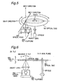
- the line linking the center of the optical disc 501 and the light spot focused onto the optical disc 501 from the optical head 502 is called the radial direction 504, and the direction perpendicular to the aforementioned radial direction 504 in the plane of the optical disc 501 is called the tangential direction 505.
- the direction perpendicular to the plane of the optical disc 501 is called the z-axis direction 506.
- tilt When distinguished by direction, tilt comprises radial direction tilt in an orthogonal direction to the track and tangential direction tilt in a parallel direction to the track.
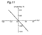
- a difference signal output (in this case, a push-pull TE signal) is reproduced by a two-split photo detector when tracking is off.
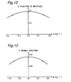
- the amplitude H of the wobble signal which is the detection value detected by the tilt detecting section 107
- the R tilt is +0.4° or -0.4°
- the tilt correcting section 108 transmits a tilt correction value corresponding to this detection value to the tilt controlling section 109, and the R tilt angle is corrected by the tilt controlling section 109 driving the tilt platform 103.
- the application of this R tilt detection method is not limited to the optical conditions used in this simulation.
- the tilt detection value has a standard value of 1 when 100% of the light is reflected back by the mirror section in the two-split photo detector.
- Fig. 8 illustrates the layout of the pits on the optical disc.
- 801 is a groove track of a guide groove formed in a spiral shape in order to record data
- 802 is a land track which lies between groove tracks.
- 803 is a first half repeated pit sequence formed such that it is displaced to the outer side or inner side from the center of the groove track
- 804 is a second half repeated pit sequence formed consecutively to the aforementioned first half repeated pit sequence, such that it is displaced from the center of the groove track in a symmetrical position to the aforementioned first half repeated pit sequence, with respect to the track center.
- the pits are formed in repeating patterns, wherein the pit-to-pit interval of the displaced bit sequences in the radial direction is 1.19 ⁇ m, the pit width is 0.36 ⁇ m, the pit depth is ⁇ /6, the pit length is 0.462 ⁇ m, and the pit-to-pit interval in the tangential direction is 1.12 ⁇ m, the pits being displaced to the inner side or the outer side by a distance of 0.3 ⁇ m from the track center to the pit center.
- the space Ls forming the interval at which these shifted pits are repeated satisfies the equation Lp ⁇ Ls ⁇ 2Lp, where Lp is the bit length.
- the tilt detecting section detects the tilt angle by taking the lower signal level difference Ab - Bb as the tilt angle detection value.
- the tilt correcting section 108 transmits a tilt correction value corresponding to this detection value to the tilt controlling section 109, and the R tilt angle is corrected by the tilt controlling section 109 driving the tilt platform 103.
- the difference between the lower signal levels of the summed signal outputs from first half and second half repeated pit sequences was taken as the detection value for the tilt control section, but it is also possible to use the upper signal level difference At - Bt in the summed signal outputs of the repeated bit sequences as the tilt detection value, instead of the lower signal level difference Ab - Bb in the summed signal outputs.
- the difference between the summed signal for the first half repeated pit sequence and the summed signal for the second half repeated pit sequence may also be used in off-track detection.
- the value of the summed signals can be gathered in one of three ways: (i) finding the upper signal level; (ii) finding the lower signal level; or (iii) finding the amplitude of the sinusoidal curve. If one of the approaches (i), (ii), (iii) is adopted when using method (4) for detecting tilt, then one of the other remaining approaches is used for off-track detection. Thereby, it is possible to avoid complete coincidence between the signal used for tilt detection and the signal used for off-track detection.
- the application of this R tilt detection method is not limited to the optical conditions used in this simulation.
- the tilt detection value has a standard value of 1 when 100% of the light is reflected back by the mirror section in the two-split photo detector.
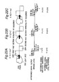
- the difference signal output of a two-split photo detector with tracking on is described. Since the device is in a tracking on state, the light spot operates along the center of the tracks.
- N1 is one two-split photo detector and N2 is a further detector.
- one of the detectors is modulated significantly by the light diffracted by the pits, whilst the other detector is not affected greatly by light diffraction due to the pits and shows little change in light intensity.
- the difference signal output is the differential output N1 - N2 of N1 and N2, and is called N-.
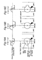
- Figs. 22A, 22B and 22C shows an example where a difference signal output from a two-split photo detector is reproduced.
- the tilt detecting section saves the amplitude difference I - J of the difference signal outputs from the first half and second half sections as the detection value of the tilt detecting section.
- the amplitude of the difference signal outputs for the first half and second half sections are saved as DC voltage values by a sample hold circuit, the differential I - J between the saved value I for the first half difference signal output and the saved value J for the second half difference signal output is taken as a tilt detection value, and the tilt control section takes this tilt detection value as the tilt angle and corrects the tilt angle accordingly.
- Fig. 15 shows simulation results for the relationship between the amount of R tilt in a state where R tilt occurs and the detection value I - J detected by the tilt detecting section.
- the tilt detecting section detects the tilt angle by taking the amplitude difference I - J between the difference signal outputs as the detection value for the tilt angle.
- the amplitude difference I - J between the difference signal outputs which is the detection value detected by the tilt detecting section 107
- the R tilt is +0.4°
- the tilt correcting section 108 transmits a tilt correction value corresponding to this detection value to the tilt controlling section 109
- the R tilt angle is corrected by the tilt controlling section 109 driving the tilt platform 103.
- the tilt detecting section detects the tilt angle by taking the amplitude difference I - J of the difference signal outputs as the detection value for the tilt angle.
- the difference between the amplitudes of the difference signal outputs from first half and second half repeated pit sequences was taken as the detection value for the tilt control section, but it is also possible to use the upper signal level difference It - Jt in the difference signal outputs of the repeated bit sequences as the tilt detection value, instead of the amplitude difference I - J in the summed signal outputs.
- the application of this R tilt detection method is not limited to the optical conditions used in this simulation.
- the tilt detection value has a standard value of 1 when 100% of the light is reflected back by the mirror section in the two-split photo detector.
- Fig. 9 shows a view of the configuration of pits on an optical disc containing isolated pits and a reproduction signal waveform relating to same.
- 901 is a groove track of a guide groove formed in a spiral shape in order to record data
- 902 is a land track which lies between groove tracks.
- 903 denotes first half isolated pits formed by deviating to the outer side or inner side from the center of the groove track
- 904 denotes second half isolated pits formed consecutively to the aforementioned first half isolated pits, by deviating from the center of the groove track in a symmetrical position to the aforementioned first half isolated pits with respect to the track center.
- the reproduced signal waveform is an example of a reproduced summed signal output from a two-split photo detector.
- the light spot operates along the center of the tracks.
- the amplitudes of the summed signal outputs for the first half and second half sections are saved as DC voltage values by a sample hold circuit, the differential E - F between the saved value E for the first half summed signal output and the saved value F for the second half summed signal output is taken as a tilt detection value, and the tilt control section takes this tilt detection value as the tilt angle and corrects the tilt angle accordingly.
- the tilt detecting section detects the tilt angle by taking the lower signal level difference E - F of the summed signal outputs as the tilt angle detection value.
- the tilt correcting section 108 transmits a tilt correction value corresponding to this detection value to the tilt controlling section 109, and the R tilt angle is corrected by the tilt controlling section 109 driving the tilt platform 103.
- the application of this R tilt detection method is not limited to the optical conditions used in this simulation.
- the tilt detection value has a standard value of 1 when 100% of the light is reflected back by the mirror section in the two-split photo detector.
- the light spot scans along the center of a track formed previously by a guide groove.
- the divergence between the center of the track of the optical disc and the light spot is called the off-track. If the off-track is 0, in other words, if the R tilt is detected by one of the methods (1) to (6) above in a case where the light spot is scanning along the center of a guide groove formed previously in the optical disc, then it is possible to detect R tilt more accurately.
- Off-track is controlled using the summed signal output of a signal reproduced by a light spot from a repeated pit sequence formed previously on the optical disc in a deviating fashion.
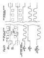
- Fig. 24 illustrates the layout of the pits on the optical disc.
- 2401 is a groove track of a guide groove formed in a spiral shape in order to record data
- 2402 is a land track which lies between groove tracks.
- 2403 is a first half repeated pit sequence formed by deviating to the outer side or inner side from the center of the groove track
- 2404 is a second half repeated pit sequence formed consecutively to the aforementioned first half repeated pit sequence, by deviating from the center of the groove track in a symmetrical position to the aforementioned first half repeated pit sequence with respect to the track center.
- the pits are formed in repeating patterns, wherein the pit-to-pit interval of the displaced bit sequences in the radial direction is 1.19 ⁇ m, the pit width is 0.36 ⁇ m, the pit depth is ⁇ /6, the bit length is 0.462 ⁇ m, and the pit-to-pit interval in the tangential direction is 1.12 ⁇ m, the pits being displaced to the inner side or the outer side by a distance of 0.3 ⁇ m from the track center to the pit center.
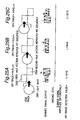
- Figs. 25A, 25B and 25C each shows an example where a summed signal output from a two-split photo detector is reproduced.
- the amplitude of the summed signal outputs for the first half and second half sections are saved as DC voltage values by a sample hold circuit, the differential L - M between the saved value L for the first half summed signal output and the saved value M for the second half summed signal output is taken as an off-track detection value, and this detection value is taken as the off-track position and the off-track position is corrected accordingly. In this case, it is possible to correct the off-track position regardless of the tilt.
- R tilt is caused by distortion of the disc, and therefore the magnitude of R tilt changes from the inner side to the outer side of the optical disc, as illustrated by curve 1001 in Fig. 10.
- 1001 is a tilt curve for representing the manner in which the inclination (tilt) of the recording surface of the optical disc with respect to the optical axis of the light beam changes with radial position on the optical disc
- 1002 is a quantity of tilt (or tilt angle) at a prescribed radial position on the inner side of the tilt curve 1001
- 1003 is a quantity of tilt at a prescribed radial position in the middle portion of the tilt curve 1001
- 1004 is a quantity of tilt at a prescribed radial position on the outer side of the tilt curve 1001.
- 1005 is a quantity of tilt derived from the detection value detected by the aforementioned tilt detecting section at a prescribed radial position on the inner side of the optical disc
- 1006 is a quantity of tilt derived from the detection value detected by the aforementioned tilt detecting section at a prescribed radial position on the outer side of the optical disc.
- 1007 is a quantity of tilt derived from the detection value detected by the aforementioned tilt detecting section at a prescribed radial position in the middle portion of the optical disc
- 1008 is an interpolated curve 1008 which connects the quantity of tilt 1007 derived for the middle circumference, with the quantity of tilt 1005 derived for the inner side and the quantity of tilt 1006 derived for the outer circumference by straight lines.
- the quantity of tilt is different at the inner side and the outer side of the disc.
- the quantity of tilt is detected at at least three radial positions, namely, the inner circumference, outer circumference, and middle circumference of the optical disc, as shown in Fig. 10.
- the quantity of tilt at a prescribed radial position between the inner and middle radial positions where the tilt angle is detected is derived from the value, at the prescribed radial position, of the curve 1008 linking the quantity of tilt 1005 derived from the detection value at the inner circumference with the quantity of tilt 1007 derived from the detection value at the middle circumference.
- the quantity of tilt at a prescribed radial position between the outer and middle radial positions where the tilt angle is detected is derived from the value, at the prescribed radial position, of the curve 1008 linking the quantity of tilt 1006 derived from the detection value at the outer circumference with the quantity of tilt 1007 derived from the detection value at the middle circumference.
- Fig. 26 illustrates the operation of a calculating circuit 104 which functions by receiving outputs a, b, c, d from four photo detecting elements in a four-split detector 100.
- This calculating circuit 104 generates:
- the TE signal is transmitted to the tracking control section 106, and is used to control the tracking position of the light spot on the track of the optical disc.
- the FE signal is transmitted to the focus control section 105, and is used to control the focal position of the light spot on the track of the optical disc.
- the RF signal is a reproduction signal obtained by reading out data recorded on the optical disc, and it is submitted to data processing.
- the RF signal is transmitted to the off-track detecting section 110, where it is used to detect the off-track position.
- the off-track detection signal (OF signal) is transmitted to the off-track detecting section 110, where it is used to detect the off-track position.
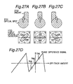
- the off-track position is detected by extracting the phase difference between two off-track detection signals.
- the intensity of the diffracted light at the detector will be as illustrated in Fig. 27B, and hence the diagonal difference signal (a+c) - (b+d) will be 0. Even if the light spot and pit sequences proceed in the direction of the arrow as the disc rotates, this value will always remain zero. If, however, the light spot is displaced from the track, as in Fig. 27A or Fig.
- the diagonal difference signals will both assume a sinusoidal output, and since these outputs have a +90° or -90° phase relationship with respect to the RF signal (a+b+c+d), it is possible to detect how far the light spot is off track from the center of the pits by detecting the phase difference between the diagonal difference signals and the RF signal.
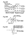
- the displacement width Wa of the first half section pre-pits is equal to the displacement width Wb of the second half section pre-pits Wb.
- Fig. 28B is a graph of the phase difference signal derived from the diagonal difference signal centered on a pit.
- the phase difference signal output is Pa
- the phase difference signal output is Pb
- Fig. 28C illustrates the results obtained when the phase difference signal for the first half section pre-pit sequence and the phase difference signal for the second half section pre-pit sequence are saved and the sum of the first half section pre-pit sequence output and the second half section pre-pit sequence output is calculated by the off-track detecting section. If the light spot passes through the center of the track, then this phase difference signal will be 0.
- the results described here are obtained from a computer simulation based on the following conditions.
- Fig. 29 illustrates the characteristics obtained when R tilt occurs.
- Fig. 29 shows the off-track detection signals calculated from the phase difference signals from the first half section displaced pits and the second half section displaced pits, in cases where, in the order (a), (b), (c), an R tilt of -0.6°, ⁇ 0.0°, and +0.6° is applied.
- the horizontal axis represents the amount of off-track with respect to the track center.
- the vertical axis represents the off-track detection signal.
- tracking accuracy is improved, cross-erasure effects, whereby adjacent tracks are erased during recording, can be eliminated, and the quality of signals recorded onto adjacent tracks can be improved.
- the optical disc device and the optical disc tilt control method it is possible to improve signal quality during recording and reproduction, without needing to provide an optical system for detecting tilt angle separately from the optical system for recording and reproduction, by detecting a tracking signal and a tilt angle, independently or in combination with each other, by a groove track, land track and repeated pit sequences formed such that the centers thereof are displaced towards the outside or the inside from the center of the groove track, previously recorded on an optical disc, and correcting the tilt angle by a tilt correcting section and a tilt controlling section. Consequently, it is not necessary to provide a separate tilt detector, thereby enabling the installation size of the device to be reduced and allowing costs to be restricted.
Landscapes
- Physics & Mathematics (AREA)
- Mathematical Physics (AREA)
- Optics & Photonics (AREA)
- Engineering & Computer Science (AREA)
- Signal Processing (AREA)
- Optical Recording Or Reproduction (AREA)
Claims (4)
- Neigungs-Erfassungsvorrichtung zum Erfassen der Neigung einer Aufzeichnungsoberfläche einer optischen Disk (101) mit konzentrischen oder fortlaufenden Spiralspuren, wobei die Neigungs-Erfassungsvorrichtung aufweist:einen optischen Kopf (102) zum Aufzeichnen und Wiedergeben von Signalen durch Fokussieren eines Lichtpunktes auf der optischen Disk;eine Fokus-Steuerungseinrichtung (105) zum Steuern des Fokus des Lichtpunktes auf der Oberfläche der optischen Disk;eine Spurfolge-Steuerungseinrichtung (106) zum Steuern der Position des Lichtpunktes auf der Spur;einen Vierteilungs-Fotodetektor (100) zum Empfangen von von der optischen Disk reflektiertem Licht, wobei der Fotodetektor vier Elemente aufweist, welche durch eine Linie parallel zu der Spurrichtung und einer Linie orthogonal zu der Mittellinie geteilt sind;eine Signal-Erzeugungseinrichtung (104) zum Empfangen von Ausgangssignalen von dem Vierteilungs-Fotodetektor und zum Erzeugeneines Fokus-Fehlersignals;eines Spurfolge-Fehlersignals;eines Gesamtsignals, das durch Addieren der Ausgangssignale von den vier Elementen erhalten wird; undeines Außer-Spur-Erfassungssignals, das durch Verwendung zweier Diagonal-Summensignale erhalten wird, wobei jedes Diagonal-Summensignal durch Addieren von Ausgangssignalen von zwei diagonal angeordneten Elementen erhalten wird;eine Außer-Spur-Erfassungseinrichtung (110, 111) zum Erfassen eines Außer-Spur-Betrages des Lichtpunktes basierend auf das Außer-Spur-Erfassungssignal;einen Zweiteilungs-Fotodetektor (100) mit zwei Elementen, welche durch eine parallel zu der Mittellinie verlaufende Linie geteilt sind;und eine Neigungs-Erfassungseinrichtung (107) zum Erfassen der Neigung der Aufzeichnungsoberfläche der optischen Disk, während der Lichtpunkt im Wesentlichen in der Mitte der Spur durch die Steuerung der Spurfolge-Steuerungseinrichtung und der Außer-Spur-Erfassungseinrichtung angeordnet ist,dadurch gekennzeichnet, dass
die Neigungs-Erfassungseinrichtung so angepasst ist, dass sie die Neigung der Aufzeichnungsoberfläche der optischen Disk (101) mit ersten verschobenen Pits und zweiten verschobenen Pits erfasst, die so ausgebildet sind, dass die ersten verschobenen Pits und zweiten verschobenen Pits jeweils zu einer ersten Seite und einer zweiten Seite einer Spur von der Mitte der Spur versetzt sind, und
die Neigungs-Erfassungseinrichtung (107) so angepasst ist, dass die Neigung der Aufzeichnungsoberfläche der optischen Disk durch einen Vergleich eines ersten Differenzsignals, das die Differenz zwischen Ausgangssignalen von den zwei Elementen des Zweiteilungs-Fotodetektors repräsentiert, wenn von den ersten verschobenen Pits reflektiertes Licht durch den Zweiteilungs-Fotodetektor empfangen wird, mit einem zweiten Differenzsignal, das die Differenz zwischen Ausgangssignalen von zwei Elementen des Zweiteilungs-Fotodetektors repräsentiert, wenn von den zweiten verschobenen Pits reflektiertes Licht von dem Zweiteilungs-Fotodetektor empfangen wird. - Neigungs-Erfassungseinrichtung nach Anspruch 1,
dadurch gekennzeichnet, dass die ersten verschobenen Pits in einer wiederholten fortlaufenden Weise bereitgestellt werden und dass die zweiten verschobenen Pits in einer wiederholten fortlaufenden Weise, anschließend an die ersten verschobenen Pits, bereitgestellt werden. - Neigungs-Erfassungsvorrichtung nach Anspruch 2,
dadurch gekennzeichnet, dass ein Abstand Ls, der das Intervall repräsentiert, in welchem die ersten verschobenen Pits wiederholt werden, so vorhanden ist, dass Lp<Ls<2Lp gilt, wobei Lp die Pit-Länge ist. - Neigungs-Erfassungsvorrichtung nach Anspruch 1,
dadurch gekennzeichnet, dass der Zweiteilungs-Fotodetektor (100) unter Verwendung zumindest eines Abschnittes des Vierteilungs-Fotodetektors (100) gebildet ist.
Priority Applications (3)
| Application Number | Priority Date | Filing Date | Title |
|---|---|---|---|
| EP99115617A EP0987691B1 (de) | 1998-09-14 | 1999-07-08 | Neigungserkennungsvorrichtung, optisches Speicher und Wiedergabe-Plattengerät, und Neigungserkennungsverfahren |
| EP99115615A EP0986053B1 (de) | 1998-09-14 | 1999-07-08 | Neigungserkennungsvorrichtung, optisches Speicher und Wiedergabe-Plattengerät, und Neigungserkennungsverfahren |
| EP99115616A EP0987690B1 (de) | 1998-09-14 | 1999-07-08 | Neigungserkennungsvorrichtung, optisches Speicher und Wiedergabe-Plattengerät, und Neigungserkennungserfahren |
Applications Claiming Priority (4)
| Application Number | Priority Date | Filing Date | Title |
|---|---|---|---|
| JP25990498 | 1998-09-14 | ||
| JP25990498 | 1998-09-14 | ||
| JP36454998 | 1998-12-22 | ||
| JP36454998 | 1998-12-22 |
Related Child Applications (3)
| Application Number | Title | Priority Date | Filing Date |
|---|---|---|---|
| EP99115615A Division EP0986053B1 (de) | 1998-09-14 | 1999-07-08 | Neigungserkennungsvorrichtung, optisches Speicher und Wiedergabe-Plattengerät, und Neigungserkennungsverfahren |
| EP99115617A Division EP0987691B1 (de) | 1998-09-14 | 1999-07-08 | Neigungserkennungsvorrichtung, optisches Speicher und Wiedergabe-Plattengerät, und Neigungserkennungsverfahren |
| EP99115616A Division EP0987690B1 (de) | 1998-09-14 | 1999-07-08 | Neigungserkennungsvorrichtung, optisches Speicher und Wiedergabe-Plattengerät, und Neigungserkennungserfahren |
Publications (3)
| Publication Number | Publication Date |
|---|---|
| EP0987689A2 EP0987689A2 (de) | 2000-03-22 |
| EP0987689A3 EP0987689A3 (de) | 2002-12-11 |
| EP0987689B1 true EP0987689B1 (de) | 2006-11-02 |
Family
ID=26544348
Family Applications (4)
| Application Number | Title | Priority Date | Filing Date |
|---|---|---|---|
| EP99115616A Expired - Lifetime EP0987690B1 (de) | 1998-09-14 | 1999-07-08 | Neigungserkennungsvorrichtung, optisches Speicher und Wiedergabe-Plattengerät, und Neigungserkennungserfahren |
| EP99115615A Expired - Lifetime EP0986053B1 (de) | 1998-09-14 | 1999-07-08 | Neigungserkennungsvorrichtung, optisches Speicher und Wiedergabe-Plattengerät, und Neigungserkennungsverfahren |
| EP99115617A Expired - Lifetime EP0987691B1 (de) | 1998-09-14 | 1999-07-08 | Neigungserkennungsvorrichtung, optisches Speicher und Wiedergabe-Plattengerät, und Neigungserkennungsverfahren |
| EP99113218A Expired - Lifetime EP0987689B1 (de) | 1998-09-14 | 1999-07-08 | Neigungserkennungsvorrichtung, optisches Plattengerät, und Neigungssteuerverfahren |
Family Applications Before (3)
| Application Number | Title | Priority Date | Filing Date |
|---|---|---|---|
| EP99115616A Expired - Lifetime EP0987690B1 (de) | 1998-09-14 | 1999-07-08 | Neigungserkennungsvorrichtung, optisches Speicher und Wiedergabe-Plattengerät, und Neigungserkennungserfahren |
| EP99115615A Expired - Lifetime EP0986053B1 (de) | 1998-09-14 | 1999-07-08 | Neigungserkennungsvorrichtung, optisches Speicher und Wiedergabe-Plattengerät, und Neigungserkennungsverfahren |
| EP99115617A Expired - Lifetime EP0987691B1 (de) | 1998-09-14 | 1999-07-08 | Neigungserkennungsvorrichtung, optisches Speicher und Wiedergabe-Plattengerät, und Neigungserkennungsverfahren |
Country Status (9)
| Country | Link |
|---|---|
| US (4) | US6549493B1 (de) |
| EP (4) | EP0987690B1 (de) |
| KR (1) | KR100365661B1 (de) |
| CN (3) | CN1209756C (de) |
| AU (1) | AU755865B2 (de) |
| BR (1) | BR9907115A (de) |
| CA (1) | CA2309696C (de) |
| DE (4) | DE69900012T2 (de) |
| WO (1) | WO2000016321A1 (de) |
Families Citing this family (38)
| Publication number | Priority date | Publication date | Assignee | Title |
|---|---|---|---|---|
| JP4258046B2 (ja) * | 1998-11-17 | 2009-04-30 | ソニー株式会社 | ディスクドライブ装置 |
| JP3776620B2 (ja) * | 1999-03-24 | 2006-05-17 | パイオニア株式会社 | 方向検出装置及び方向検出方法 |
| JP2000339727A (ja) * | 1999-05-18 | 2000-12-08 | Lg Electronics Inc | 光記録媒体の記録再生方法 |
| KR100606669B1 (ko) * | 1999-05-19 | 2006-07-31 | 엘지전자 주식회사 | 광 기록매체의 기록재생 방법 |
| US7214232B2 (en) * | 1999-07-23 | 2007-05-08 | Ethicon, Inc. | Graft fixation device |
| JP2001056952A (ja) * | 1999-08-19 | 2001-02-27 | Hitachi Ltd | 光ヘッド装置およびその製造方法 |
| JP4125458B2 (ja) * | 1999-10-28 | 2008-07-30 | 松下電器産業株式会社 | 光ディスク装置 |
| WO2002001554A1 (en) * | 2000-06-26 | 2002-01-03 | Matsushita Electric Industrial Co., Ltd. | Optical head |
| US6970404B2 (en) * | 2000-10-05 | 2005-11-29 | Matsushita Electric Industrial Co., Ltd. | Information recording/reproducing apparatus |
| CN1324579C (zh) * | 2001-03-30 | 2007-07-04 | 三星电机株式会社 | 倾斜检测器和倾斜检测的方法 |
| JP2003077156A (ja) * | 2001-06-20 | 2003-03-14 | Mitsubishi Electric Corp | 光ヘッド装置 |
| JP2003141761A (ja) * | 2001-10-31 | 2003-05-16 | Sanyo Electric Co Ltd | 光ディスク装置および記録/再生方法 |
| JP4287288B2 (ja) | 2002-04-02 | 2009-07-01 | コーニンクレッカ フィリップス エレクトロニクス エヌ ヴィ | 多次元アクチュエータを利用してチルト補正を実行する方法及び装置 |
| JP2004047043A (ja) * | 2002-05-13 | 2004-02-12 | Nec Corp | 光ディスク媒体およびドライブ装置 |
| KR20030093683A (ko) * | 2002-06-05 | 2003-12-11 | 삼성전자주식회사 | 호환형 광픽업 |
| TW589634B (en) * | 2002-06-11 | 2004-06-01 | Benq Corp | Method for adjusting mechanical error of optical disc reading device |
| JP2004022127A (ja) * | 2002-06-19 | 2004-01-22 | Pioneer Electronic Corp | チルト補正装置 |
| KR100888590B1 (ko) * | 2002-07-11 | 2009-03-16 | 삼성전자주식회사 | 래디얼 틸트 검출 방법 및 그 장치 |
| JP2005534129A (ja) * | 2002-07-24 | 2005-11-10 | コーニンクレッカ フィリップス エレクトロニクス エヌ ヴィ | 再書き込み可能な光媒体、当該光媒体を読み取る及び/又は当該光媒体に書き込む装置、及び再書き込み可能なディスクを製造する方法。 |
| JP2004264808A (ja) * | 2003-01-07 | 2004-09-24 | Shinohara Yasuko | 光学顕微鏡および天体望遠鏡の結像方法 |
| JP3947875B2 (ja) * | 2003-03-10 | 2007-07-25 | 日本電気株式会社 | 光ディスク媒体及び光ディスク記録再生方法 |
| DE10319757A1 (de) * | 2003-04-30 | 2004-11-18 | Deutsche Thomson-Brandt Gmbh | Wiedergabe- oder Aufzeichnungsgerät für optische Aufzeichnungsträger mit einer Neigungsregelung |
| CN1791911A (zh) * | 2003-05-21 | 2006-06-21 | 皇家飞利浦电子股份有限公司 | 盘驱动器装置和倾斜补偿方法 |
| JP2005071527A (ja) * | 2003-08-27 | 2005-03-17 | Tdk Corp | 光記録媒体の反り角測定装置及び反り角測定方法 |
| CN100369131C (zh) * | 2003-09-03 | 2008-02-13 | 联发科技股份有限公司 | 光学头倾斜角度调整方法 |
| JP3989889B2 (ja) * | 2003-09-19 | 2007-10-10 | 株式会社リコー | 収差調整装置、光ピックアップ、プログラム、及び記憶媒体 |
| TWI260013B (en) * | 2003-12-04 | 2006-08-11 | Mediatek Inc | Optical incidence auto-adjusting system |
| JP2005166195A (ja) * | 2003-12-04 | 2005-06-23 | Canon Inc | 光情報記録再生装置及び光情報記録再生方法 |
| JP2005196896A (ja) * | 2004-01-08 | 2005-07-21 | Toshiba Corp | 光ディスク装置およびその制御方法 |
| JP4537780B2 (ja) * | 2004-06-30 | 2010-09-08 | パイオニア株式会社 | チルト補正装置及び方法、情報記録装置、並びに情報記録再生装置 |
| US7414929B2 (en) * | 2004-09-22 | 2008-08-19 | Lsi Corporation | Optical disc tilt detection and tilt servo control method |
| WO2006126242A1 (ja) | 2005-05-23 | 2006-11-30 | Renesas Technology Corp. | 光ディスク装置 |
| TWI292905B (en) * | 2005-06-20 | 2008-01-21 | Mediatek Inc | Control circuit of optical storage device and method thereof |
| EP1764791A1 (de) * | 2005-09-16 | 2007-03-21 | Deutsche Thomson-Brandt Gmbh | Verfahren und Gerät zum Lesen von winkelgemultiplexten Pits |
| US20070133365A1 (en) * | 2005-12-12 | 2007-06-14 | Shih-Hao Ko | Tilt calibration apparatus and method capable of adjusting included angle between optical pick-up head and optical disc according to wobble signal |
| US20080025168A1 (en) * | 2006-07-27 | 2008-01-31 | Chi-Mou Chao | Methods for determining relationship between main beam and side beam in optical storage device and related apparatuses |
| JP2010015655A (ja) * | 2008-07-04 | 2010-01-21 | Hitachi Ltd | 光ディスク装置及びそのチルト制御方法 |
| CN103035264B (zh) * | 2011-09-29 | 2015-07-08 | 凌阳科技股份有限公司 | 数据还原装置与方法 |
Family Cites Families (50)
| Publication number | Priority date | Publication date | Assignee | Title |
|---|---|---|---|---|
| JPH0680535B2 (ja) | 1982-08-27 | 1994-10-12 | 株式会社日立製作所 | 情報の記録再生方法 |
| JPS59191144A (ja) * | 1983-04-14 | 1984-10-30 | Sony Corp | 光ピツクアツプのトラツキングサ−ボ回路 |
| JPS59191143A (ja) | 1983-04-15 | 1984-10-30 | Hitachi Ltd | 光学的トラツク追跡装置 |
| JPS60143448A (ja) * | 1983-12-29 | 1985-07-29 | Sony Corp | スキユ−エラ−検出回路 |
| US4748609A (en) * | 1985-03-29 | 1988-05-31 | Hitachi, Ltd. | Method and apparatus for composite tracking servo system with track offset correction and rotary optical disc having at least one correction mark for correcting track offset |
| JPS61294640A (ja) | 1985-06-21 | 1986-12-25 | Hitachi Ltd | 光学的情報記録再生方式 |
| JPS6233338A (ja) | 1985-07-30 | 1987-02-13 | オプテイカル ストレツジ インタ−ナシヨナル−ユ−エス | デ−タ記憶装置用記録キヤリア |
| US4959823A (en) | 1985-07-30 | 1990-09-25 | Laser Magnetic Storage International Company | Tracking and seeking system for use with an optical record carrier having a wobbled track format |
| US4879708A (en) | 1985-07-30 | 1989-11-07 | Laser Magnetic Storage International Company | Optical disk tracking and seeking systems specific track formats using wobbled pits |
| JPS6289246A (ja) * | 1985-10-16 | 1987-04-23 | Sankyo Seiki Mfg Co Ltd | 光記録媒体傾き検出装置 |
| US4866688A (en) | 1985-12-20 | 1989-09-12 | Hitachi, Ltd. | Composite tracking servo system for optical disc apparatus with track offset correction |
| JPS62232732A (ja) | 1986-04-03 | 1987-10-13 | Victor Co Of Japan Ltd | 光学的情報信号再生装置 |
| JPS63149841A (ja) * | 1986-12-13 | 1988-06-22 | Hitachi Ltd | 光学式情報読取装置のデイスク傾き検出装置 |
| JP2911449B2 (ja) * | 1987-10-29 | 1999-06-23 | パイオニア株式会社 | 光学式情報読取装置 |
| JPH01302546A (ja) * | 1988-05-30 | 1989-12-06 | Sankyo Seiki Mfg Co Ltd | 変位検出方法 |
| JPH01312744A (ja) | 1988-06-13 | 1989-12-18 | Mitsubishi Electric Corp | 光学式情報再生装置 |
| JP2705207B2 (ja) | 1989-04-28 | 1998-01-28 | 松下電器産業株式会社 | オフトラック検出装置 |
| JPH0410231A (ja) | 1990-04-27 | 1992-01-14 | Kenwood Corp | 光ディスクの情報トラック蛇行検出装置 |
| JP2866160B2 (ja) * | 1990-07-19 | 1999-03-08 | パイオニア株式会社 | 光学式ディスクプレーヤ |
| JP3072767B2 (ja) * | 1990-07-24 | 2000-08-07 | パイオニア株式会社 | 光学式ディスクプレーヤ |
| JPH04229423A (ja) | 1990-12-27 | 1992-08-18 | Ricoh Co Ltd | 光ピックアップの傾き補正装置 |
| JPH04332920A (ja) | 1991-05-02 | 1992-11-19 | Olympus Optical Co Ltd | 光学的情報記録再生装置 |
| US5404345A (en) * | 1991-06-07 | 1995-04-04 | Brother Kogyo Kabushiki Kaisha | Optical recording medium and tracking servo circuit adapted therefor using wobbled pits |
| JPH06289246A (ja) * | 1993-04-05 | 1994-10-18 | Nippon Telegr & Teleph Corp <Ntt> | 波長多重分離結合回路 |
| JP3161891B2 (ja) * | 1993-11-16 | 2001-04-25 | 松下電器産業株式会社 | ディスクチルト検出装置およびディスクチルト補正装置 |
| JPH07141674A (ja) * | 1993-11-18 | 1995-06-02 | Sony Corp | 光ディスク、光ディスク再生方法及び光ディスク再生装置 |
| JPH0817064A (ja) * | 1994-04-27 | 1996-01-19 | Victor Co Of Japan Ltd | 光ディスク装置 |
| JPH0855341A (ja) * | 1994-08-12 | 1996-02-27 | Matsushita Electric Ind Co Ltd | 光ディスク媒体および光ディスク装置 |
| US5898654A (en) * | 1994-07-14 | 1999-04-27 | Matsushita Electric Industrial Co., Ltd. | Optical disk and optical disk apparatus having a predetermined pattern of marks on tracks such that a reproduced signal is caused to jitter |
| JP3025472B2 (ja) | 1995-02-17 | 2000-03-27 | 松下電器産業株式会社 | 光ディスク記録/再生装置 |
| US5805543A (en) * | 1995-02-22 | 1998-09-08 | Matsushita Electric Industrial Co., Ltd. | Tilt control apparatus based on pulsed width detection of an information reproduced signal |
| JPH08279160A (ja) * | 1995-03-31 | 1996-10-22 | Sony Corp | 光学記録媒体及び光学デイスク装置 |
| JP2713229B2 (ja) | 1995-05-17 | 1998-02-16 | 株式会社日立製作所 | トラッキング方法及び光ディスク装置 |
| KR0176888B1 (ko) * | 1996-01-24 | 1999-04-15 | 구자홍 | 광디스크 기록재생기의 서보 제어 장치 |
| US6418095B1 (en) * | 1996-06-18 | 2002-07-09 | Matsushita Electric Industrial Co., Ltd. | Optical head device, inclination detection apparatus using the same, and optical information processing apparatus using the same |
| JPH1083549A (ja) * | 1996-09-05 | 1998-03-31 | Sanyo Electric Co Ltd | ディスクプレーヤーのティルト制御方法 |
| JP2842403B2 (ja) | 1996-09-11 | 1999-01-06 | 日本電気株式会社 | 光ディスク装置のチルト補正方法および光ディスク装置 |
| JPH1091971A (ja) * | 1996-09-12 | 1998-04-10 | Sony Corp | 光学式ディスク装置のトラッキング制御装置とその方法 |
| US5914925A (en) * | 1997-01-10 | 1999-06-22 | Eastman Kodak Company | DRDW differential phase tracking method and apparatus |
| JP3211002B2 (ja) | 1997-04-24 | 2001-09-25 | 富士通株式会社 | 光記録媒体、チルト検出器、光ディスク装置、チルト検出方法及びチルト補正方法 |
| JPH10312565A (ja) | 1997-05-14 | 1998-11-24 | Olympus Optical Co Ltd | 光ディスク駆動装置 |
| JPH1116216A (ja) * | 1997-06-19 | 1999-01-22 | Sony Corp | 光ディスク及び光ディスク装置 |
| JPH11144281A (ja) | 1997-11-13 | 1999-05-28 | Sony Corp | ディスク再生装置 |
| JPH11161987A (ja) | 1997-11-25 | 1999-06-18 | Sony Corp | スキュー検出装置 |
| JP3545196B2 (ja) * | 1998-03-20 | 2004-07-21 | パイオニア株式会社 | チルトサーボ制御装置 |
| KR100618962B1 (ko) * | 1998-08-29 | 2006-09-01 | 삼성전자주식회사 | 서보 에러 검출 방법, 이에 적합한 장치, 트랙킹 에러 검출 방법, 그리고 틸트 에러 검출방법 |
| US6459664B1 (en) * | 1998-08-31 | 2002-10-01 | Matsushita Electric Industrial Co., Ltd. | Optical disc tilt control apparatus |
| JP2000132855A (ja) * | 1998-10-27 | 2000-05-12 | Matsushita Electric Ind Co Ltd | 光情報記録再生装置 |
| JP3688482B2 (ja) | 1998-10-29 | 2005-08-31 | パイオニア株式会社 | 傾斜検出装置 |
| JP2007149841A (ja) * | 2005-11-25 | 2007-06-14 | Toyota Motor Corp | 熱発電装置 |
-
1999
- 1999-07-08 DE DE69900012T patent/DE69900012T2/de not_active Expired - Lifetime
- 1999-07-08 EP EP99115616A patent/EP0987690B1/de not_active Expired - Lifetime
- 1999-07-08 EP EP99115615A patent/EP0986053B1/de not_active Expired - Lifetime
- 1999-07-08 DE DE69900013T patent/DE69900013T2/de not_active Expired - Lifetime
- 1999-07-08 DE DE69900014T patent/DE69900014T2/de not_active Expired - Lifetime
- 1999-07-08 DE DE69933830T patent/DE69933830T2/de not_active Expired - Lifetime
- 1999-07-08 EP EP99115617A patent/EP0987691B1/de not_active Expired - Lifetime
- 1999-07-08 EP EP99113218A patent/EP0987689B1/de not_active Expired - Lifetime
- 1999-07-13 CN CNB998016071A patent/CN1209756C/zh not_active Expired - Lifetime
- 1999-07-13 CN CNB2004100768046A patent/CN100334621C/zh not_active Expired - Fee Related
- 1999-07-13 CA CA002309696A patent/CA2309696C/en not_active Expired - Lifetime
- 1999-07-13 US US09/352,203 patent/US6549493B1/en not_active Expired - Lifetime
- 1999-07-13 AU AU46512/99A patent/AU755865B2/en not_active Expired
- 1999-07-13 BR BR9907115-0A patent/BR9907115A/pt not_active Application Discontinuation
- 1999-07-13 WO PCT/JP1999/003761 patent/WO2000016321A1/en not_active Ceased
- 1999-07-13 KR KR1020007005250A patent/KR100365661B1/ko not_active Expired - Lifetime
- 1999-07-13 CN CNB2004100768050A patent/CN1319055C/zh not_active Expired - Fee Related
- 1999-08-23 US US09/379,494 patent/US6169715B1/en not_active Expired - Lifetime
- 1999-08-23 US US09/379,495 patent/US6167009A/en not_active Expired - Lifetime
- 1999-08-23 US US09/379,496 patent/US6157600A/en not_active Expired - Lifetime
Also Published As
Similar Documents
| Publication | Publication Date | Title |
|---|---|---|
| EP0987691B1 (de) | Neigungserkennungsvorrichtung, optisches Speicher und Wiedergabe-Plattengerät, und Neigungserkennungsverfahren | |
| KR100625156B1 (ko) | 광 디스크의 경사 검출 방법, 광 디스크의 경사 제어 방법, 광 픽업 디바이스 및 광 디스크 디바이스 | |
| US7072279B2 (en) | Optical reproducing method for optical medium with aligned prepit portion | |
| US7110334B2 (en) | Method for detecting servo error, apparatus therefor, disk which maintains quality of servo error signal, method of controlling servo of disk recording/reproducing apparatus, method of detecting tracking error, and method of detecting tilt error | |
| US8184510B2 (en) | Method of recording and reproducing an optical recording medium | |
| US20020064105A1 (en) | Optical information recording medium and an optical information recording/reproduction device | |
| JP4153621B2 (ja) | チルト検出装置 | |
| AU2002301755B2 (en) | Tilt detection device, optical disc device, and tilt control method | |
| EP0944048B1 (de) | Optische Platte mit Neigungserfassungsmuster | |
| JP3401460B2 (ja) | チルト検出装置および光ディスク装置、チルト制御方法 | |
| JP3470105B2 (ja) | チルト検出装置および光ディスク装置、チルト検出方法 | |
| JP3401458B2 (ja) | チルト検出装置 | |
| JP3401459B2 (ja) | チルト検出装置および光ディスク装置、チルト制御方法 | |
| CN100407304C (zh) | 用于光记录介质的具有倾斜控制系统的重放和记录装置 | |
| KR100601727B1 (ko) | 서보 에러 및 디트랙을 검출하기 위한 피트들을 가지는디스크 | |
| US7072278B2 (en) | Optical reproducing method for optical medium with aligned prepit portion | |
| JPH1186310A (ja) | 光ディスク装置 |
Legal Events
| Date | Code | Title | Description |
|---|---|---|---|
| PUAI | Public reference made under article 153(3) epc to a published international application that has entered the european phase |
Free format text: ORIGINAL CODE: 0009012 |
|
| 17P | Request for examination filed |
Effective date: 19990819 |
|
| AK | Designated contracting states |
Kind code of ref document: A2 Designated state(s): AT BE CH CY DE DK ES FI FR GB GR IE IT LI LU MC NL PT SE |
|
| AX | Request for extension of the european patent |
Free format text: AL;LT;LV;MK;RO;SI |
|
| PUAL | Search report despatched |
Free format text: ORIGINAL CODE: 0009013 |
|
| AK | Designated contracting states |
Kind code of ref document: A3 Designated state(s): AT BE CH CY DE DK ES FI FR GB GR IE IT LI LU MC NL PT SE |
|
| AKX | Designation fees paid |
Designated state(s): DE FR GB |
|
| GRAP | Despatch of communication of intention to grant a patent |
Free format text: ORIGINAL CODE: EPIDOSNIGR1 |
|
| GRAS | Grant fee paid |
Free format text: ORIGINAL CODE: EPIDOSNIGR3 |
|
| GRAA | (expected) grant |
Free format text: ORIGINAL CODE: 0009210 |
|
| AK | Designated contracting states |
Kind code of ref document: B1 Designated state(s): DE FR GB |
|
| REG | Reference to a national code |
Ref country code: GB Ref legal event code: FG4D |
|
| REF | Corresponds to: |
Ref document number: 69933830 Country of ref document: DE Date of ref document: 20061214 Kind code of ref document: P |
|
| EN | Fr: translation not filed | ||
| PLBE | No opposition filed within time limit |
Free format text: ORIGINAL CODE: 0009261 |
|
| STAA | Information on the status of an ep patent application or granted ep patent |
Free format text: STATUS: NO OPPOSITION FILED WITHIN TIME LIMIT |
|
| 26N | No opposition filed |
Effective date: 20070803 |
|
| PG25 | Lapsed in a contracting state [announced via postgrant information from national office to epo] |
Ref country code: FR Free format text: LAPSE BECAUSE OF FAILURE TO SUBMIT A TRANSLATION OF THE DESCRIPTION OR TO PAY THE FEE WITHIN THE PRESCRIBED TIME-LIMIT Effective date: 20070615 |
|
| PG25 | Lapsed in a contracting state [announced via postgrant information from national office to epo] |
Ref country code: FR Free format text: LAPSE BECAUSE OF FAILURE TO SUBMIT A TRANSLATION OF THE DESCRIPTION OR TO PAY THE FEE WITHIN THE PRESCRIBED TIME-LIMIT Effective date: 20061102 |
|
| PGFP | Annual fee paid to national office [announced via postgrant information from national office to epo] |
Ref country code: GB Payment date: 20120704 Year of fee payment: 14 |
|
| PGFP | Annual fee paid to national office [announced via postgrant information from national office to epo] |
Ref country code: DE Payment date: 20120704 Year of fee payment: 14 |
|
| GBPC | Gb: european patent ceased through non-payment of renewal fee |
Effective date: 20130708 |
|
| REG | Reference to a national code |
Ref country code: DE Ref legal event code: R119 Ref document number: 69933830 Country of ref document: DE Effective date: 20140201 |
|
| PG25 | Lapsed in a contracting state [announced via postgrant information from national office to epo] |
Ref country code: DE Free format text: LAPSE BECAUSE OF NON-PAYMENT OF DUE FEES Effective date: 20140201 Ref country code: GB Free format text: LAPSE BECAUSE OF NON-PAYMENT OF DUE FEES Effective date: 20130708 |