EP0988927A2 - Verfahren zum Bearbeiten eines Werkstücks und Vorrichtung zur Erzeugung von darin verwendetem Nebel - Google Patents
Verfahren zum Bearbeiten eines Werkstücks und Vorrichtung zur Erzeugung von darin verwendetem Nebel Download PDFInfo
- Publication number
- EP0988927A2 EP0988927A2 EP99114767A EP99114767A EP0988927A2 EP 0988927 A2 EP0988927 A2 EP 0988927A2 EP 99114767 A EP99114767 A EP 99114767A EP 99114767 A EP99114767 A EP 99114767A EP 0988927 A2 EP0988927 A2 EP 0988927A2
- Authority
- EP
- European Patent Office
- Prior art keywords
- ejection
- liquids
- machining
- mist
- ejected
- Prior art date
- Legal status (The legal status is an assumption and is not a legal conclusion. Google has not performed a legal analysis and makes no representation as to the accuracy of the status listed.)
- Withdrawn
Links
Images

Classifications
-
- B—PERFORMING OPERATIONS; TRANSPORTING
- B05—SPRAYING OR ATOMISING IN GENERAL; APPLYING FLUENT MATERIALS TO SURFACES, IN GENERAL
- B05B—SPRAYING APPARATUS; ATOMISING APPARATUS; NOZZLES
- B05B7/00—Spraying apparatus for discharge of liquids or other fluent materials from two or more sources, e.g. of liquid and air, of powder and gas
- B05B7/02—Spray pistols; Apparatus for discharge
-
- B—PERFORMING OPERATIONS; TRANSPORTING
- B23—MACHINE TOOLS; METAL-WORKING NOT OTHERWISE PROVIDED FOR
- B23Q—DETAILS, COMPONENTS, OR ACCESSORIES FOR MACHINE TOOLS, e.g. ARRANGEMENTS FOR COPYING OR CONTROLLING; MACHINE TOOLS IN GENERAL CHARACTERISED BY THE CONSTRUCTION OF PARTICULAR DETAILS OR COMPONENTS; COMBINATIONS OR ASSOCIATIONS OF METAL-WORKING MACHINES, NOT DIRECTED TO A PARTICULAR RESULT
- B23Q11/00—Accessories fitted to machine tools for keeping tools or parts of the machine in good working condition or for cooling work; Safety devices specially combined with or arranged in, or specially adapted for use in connection with, machine tools
- B23Q11/10—Arrangements for cooling or lubricating tools or work
- B23Q11/1038—Arrangements for cooling or lubricating tools or work using cutting liquids with special characteristics, e.g. flow rate, quality
- B23Q11/1046—Arrangements for cooling or lubricating tools or work using cutting liquids with special characteristics, e.g. flow rate, quality using a minimal quantity of lubricant
-
- B—PERFORMING OPERATIONS; TRANSPORTING
- B23—MACHINE TOOLS; METAL-WORKING NOT OTHERWISE PROVIDED FOR
- B23Q—DETAILS, COMPONENTS, OR ACCESSORIES FOR MACHINE TOOLS, e.g. ARRANGEMENTS FOR COPYING OR CONTROLLING; MACHINE TOOLS IN GENERAL CHARACTERISED BY THE CONSTRUCTION OF PARTICULAR DETAILS OR COMPONENTS; COMBINATIONS OR ASSOCIATIONS OF METAL-WORKING MACHINES, NOT DIRECTED TO A PARTICULAR RESULT
- B23Q11/00—Accessories fitted to machine tools for keeping tools or parts of the machine in good working condition or for cooling work; Safety devices specially combined with or arranged in, or specially adapted for use in connection with, machine tools
- B23Q11/10—Arrangements for cooling or lubricating tools or work
- B23Q11/1076—Arrangements for cooling or lubricating tools or work with a cutting liquid nozzle specially adaptable to different kinds of machining operations
-
- Y—GENERAL TAGGING OF NEW TECHNOLOGICAL DEVELOPMENTS; GENERAL TAGGING OF CROSS-SECTIONAL TECHNOLOGIES SPANNING OVER SEVERAL SECTIONS OF THE IPC; TECHNICAL SUBJECTS COVERED BY FORMER USPC CROSS-REFERENCE ART COLLECTIONS [XRACs] AND DIGESTS
- Y02—TECHNOLOGIES OR APPLICATIONS FOR MITIGATION OR ADAPTATION AGAINST CLIMATE CHANGE
- Y02P—CLIMATE CHANGE MITIGATION TECHNOLOGIES IN THE PRODUCTION OR PROCESSING OF GOODS
- Y02P70/00—Climate change mitigation technologies in the production process for final industrial or consumer products
- Y02P70/10—Greenhouse gas [GHG] capture, material saving, heat recovery or other energy efficient measures, e.g. motor control, characterised by manufacturing processes, e.g. for rolling metal or metal working
Definitions
- the present invention relates generally to a method of machining a workpiece such as machine cutting and grinding and an apparatus for supplying mist which may be used in the method.
- a liquid is delivered from a water-supply nozzle extending toward the machining position.
- a tool holder 2 which is installed on the lower end of a spindle (not shown) of a body 1 and a tool connecting axis 3, is to be engaged with a machining tool 4, to which a water supply nozzle or an air supply tube 5 extends from the body 1.
- a large-scale stand type machine tool like this machining center, there may be a situation where machining performance deteriorates because water or debris easily accumulates inside a machined recess.
- the branch tube 52a supplies water while the other branch tube 52b supplies oil.
- a piston 54 held by a compression spring 53 is pushed toward the opposite side (left side in Fig.8) in the nozzle 51 so that a liquid passage 55 connected to the liquid supply tube 52 is opened. Consequently, water and oil are sprayed out in mixed fine particles from the very small outlets of nozzles 56 and 57 which are branched off toward the right and left, respectively.
- a method of machining a workpiece with a machining part comprising the steps of introducing a plurality of liquids separately into ejection means which converts each liquid into a mist form and ejecting the liquids toward a workpiece to be machined and a machining part; wherein the liquids are not mixed one another within the ejection means, the liquids each being separately converted into a mist form after being ejected from the ejection means, and machining the workpiece as the liquids, in a mist form, are supplied toward the workpiece to be machined and the machining part.
- an apparatus for supplying mist to a machine for machining a workpiece comprising ejection means for ejecting a plurality of liquids separately without mixing the liquids with one another and means for converting the liquids ejected from the ejection means into a mist form.
- the method of machining a workpiece of the present invention can be carried out by introducing a plurality of liquids into the ejection means.
- the ejection nozzle means has a single ejection nozzle and a plurality of liquids are introduced into the single ejection nozzle, since the liquids are ejected from the single ejection nozzle, it becomes easier to mix each ejected liquid.
- the ejection means has a plurality of ejection nozzles and a plurality of liquids are separately introduced into each of the corresponding ejection nozzles, respectively, since the liquids are ejected from the plurality of ejection nozzles, respectively, it becomes easier to supply the liquids into different parts, separately.
- the liquids ejected from a plurality of ejection nozzles may be mixed.
- the face side of the machining tool can be cooled by the mist of the cooling water, while the flank side of the machining tool can be lubricated by the mist of the oil cutting fluid.
- a face side of a machining tool means not only a face side of a machining tool and its adjacent portion, but also cuttings for a workpiece, or all together of the face side, its adjacent portion and cutting.
- a flank side of a machining tool means not only a flank side of a machining tool and its adjacent portion, but also a machined surface of a workpiece, or all together of the flank side, its adjacent portion and the machined surface of a workpiece.
- compressed air is ejected from an air outlet of an each ejection nozzle toward at least one ejection aperture of the ejection nozzle through which a liquid is ejected so that a flow of compressed air collides with the ejected liquid, which is to convert the liquid into a mist form. Since the compressed air is ejected from the air outlet of the ejection nozzle and then moved toward the liquids ejected from the ejection apertures of the ejection nozzle, such movement entrains the adjacent air to flow in a corresponding manner so that the amount of air to be collided with the liquids can be increased.
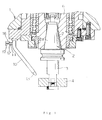
- Fig. 1 is a diagram illustrating a machining center 1 according to one embodiment of the present invention.
- the basic construction of this machining center 1 is the same as that of conventional one. That is, a spindle 6, which rotates at a high-speed, is held via a bearing inside the machining center 1.
- a tapered chuck 7 is provided at a lower end of the spindle 6.
- a taper 2a for engagement in a tool holder 2 is inserted and held detachably in the tapered chuck 7.
- a machining tool 4 is installed on a tool connecting axis 3 which is a lower part of the tool holder 2.
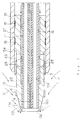
- the apparatus for supplying mist comprises an air supply tube 10, which extends perpendicularly a short distance from the machining center 1 and then extends so as to be tilted inwards; a cooling water supply tube 11, a portion of which is located inside the air supply tube 10 as shown in Fig. 2; an oil cutting fluid supply tube 12, also located inside the same air supply tube 10 as shown in Fig. 2; and a generally-cylindrical nozzle body (an ejection nozzle) 13; wherein one side of the nozzle body 13 (right side in Fig. 2) is engaged within an open end 10a of the air supply tube 10, while the other end (left side in Fig. 2) projects from the open end 10a.
- Both ends of the cooling water supply tube 11 and the oil cutting fluid supply tube 12 are inserted into an inner hole 13a of the nozzle body 13.
- a holding plate 14 is fixed in an air-tight state at an open end 13b of the nozzle body 13, such that each open end 11a, 12a of the cooling water supply tube 11 and the oil cutting fluid supply tube 12 is held and fixed in an air-tight state to a pair of through holes 14a, 14b, respectively, arranged in the holding plate 14.
- 15 is a sealer.
- the upper open of the air supply tube 10 is connected to an air supply means such as a compressor (not shown) via air supply line located inside the machining center 1.
- Ends of the cooling water supply tube 11 and the oil cutting fluid supply tube 12 respectively project from the upper part of the air supply tube 10 (see Fig. 1) and are connected via a cooling water connecting tube 16 and an oil cutting fluid connecting tube 17, respectively, with cooling water supply means (not shown), such as a cooling water tank of, for example, tap water, a pump and the like, and oil cutting fluid supply means (not shown), such as an oil cutting fluid tank, a pump and the like.
- the tank may contain an oil cutting fluid such as Bluebe #LB-1 available from US ITW Corporation.
- respective pressure regulating valves are provided in the air supply tube 10, the air supply line or the air supply means, in the cooling water supply tube 11, the cooling water connecting tube 16 or the cooling water supply means, and in the oil cutting fluid supply tube 12, the oil cutting fluid connecting tube 17 or the oil cutting fluid supply means.
- the pressure regulating valves are provided so that compressed air, cooling water and oil cutting fluid, at a specified set pressure respectively, are supplied to the air supply tube 10, the cooling water supply tube 11 and the oil cutting fluid supply tube 12.
- a smaller-diameter peripheral surface 22 formed so as to be stepped down from the larger-diameter peripheral surface 21 (i.e., formed so as to have a smaller diameter than the open end 10a of the air supply tube 10)
- a tapered surface part 23 wherein the size of the tapered part gradually becomes smaller in diameter from the small-diameter peripheral surface 22 toward a distal end so as to be shaped into a frustum of a right circular cone, the right side portion of the small-diameter peripheral surface 22 being positioned within the open end 10a of the air supply tube 10. Consequently, an annular gap 20 is formed between the open end 10a of the air supply tube 10 and the right side portion of the small-diameter peripheral surface 22.
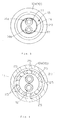
- the inner bore 13a of the nozzle body 13, except for an open end 13b, is formed to define sufficient space for the cooling water supply tube 11 and the oil cutting supply tube 12. Except for the open end 13b, eight air circulation holes (air outlets) 25 are formed radially and equidistantly at positions corresponding to the right side portion of the smaller-diameter peripheral surface 22.
- cooling water is supplied to the cooling water supply, tube 11 and oil cutting fluid is supplied to the oil cutting fluid tube 12, cooling water is ejected from the open end 11a of the cooling water supply tube 11 and oil cutting fluid is ejected from the open end 12a of the oil cutting fluid supply tube 12, respectively.
- air supplied to the air supply tube 10 flows into the inner bore 13a of the nozzle body 13, then into the gap 20 via each of the air circulation holes 25, and subsequently along the smaller-diameter peripheral surface 22 and the tapered surface part 23 (as shown by an arrow S), and finally collides with cooling water ejected from the open end 11a of the cooling water supply tube 11 and with oil cutting fluid ejected from the open end 12a of the oil cutting fluid supply tube 12. Consequently, the cooling water and the oil cutting fluid become fine particles and are formed into a mist, thereby resulting in mist mixture.
- the compressed air when compressed air flows along the smaller-diameter peripheral surface 22 and the tapered surface part 23 of the nozzle body 13, the compressed air creates a flow of adjacent air so as to form a subsidiary flow as shown by an arrow U.
- the subsidiary flow increases the mist mixture to a large amount of flow.
- the flow of the increased mist mixture has a strong thrust and strongly collides with the machined part of a workpiece and with the machining part of the machining tool 4 to be pressed on the workpiece.
- the cooling water and the oil cutting fluid are first formed into the form of a mist and then mixed together, both are fully mixed together. Further, since the cooling water and the oil cutting fluid are not mixed within the nozzle body 13, the fact that the oil cutting fluid is only admixed with the water immediately before the mixture is applied to the workpiece and the machining part can prevent the oil cutting fluid from deteriorating before it is used. Still further, the mist mixture has sufficient power to blow off debris and the like generated during machining, thereby preventing debris and the like from remaining around the workpiece to be machined and the machining part. In addition, since a large amount of flow of the mist mixture is applied, enhancement of the cooling effect results.
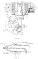
- Fig. 5 illustrates a machining center according to another embodiment of the present invention.
- the basic construction of the machining center is the same as the embodiment shown in Fig. 1.
- Fig. 5 the same components as shown in Fig. 1 are denoted by the same reference numerals.
- 4a is debris and 8 is a workpiece.
- a first and a second air supply tubes 31 and 32 extends downward, respectively, from a lower end of a machining center body 1.
- a cooling water supply tube 33 is located inside the first air supply tube 31 while an oil cutting fluid tube 34 is located inside the second air supply tube 32, both in the manner shown in Fig. 6.
- An open end of the cooling water supply tube 33 is fixed in an air-tight state to an ejection nozzle 31a of the first air supply tube 31, while an open end of the oil cutting fluid supply tube 34 is fixed in an air-tight state to ejection nozzle 32a of the second supply tube 32.
- the ejection nozzle 31a of the first air supply tube 31 is directed toward a face side of the machining tool 4, while the ejection nozzle 32a of the second air supply tube 32 is directed toward a flank side thereof.
- Fig. 5, 36 and 37 respectively, are connecting tubes for the cooling water supply tube 33 and for the oil cutting fluid supply tube 34.
- guide rings 31b, 32b externally engage with each peripheral surface of the air supply tubes 31, 32, respectively, whereby air is ejected as shown by an arrow S in Fig. 6 from a gap 35 between each outer peripheral surface of the air supply tubes 31, 32 and each inner peripheral surface of the guide rings 31b, 32b, respectively, so as to cause adjacent air to flow in a subsidiary flow as shown by an arrow U.
- cooling water is supplied in a mist form to a face side of the machining tool 4, while the oil cutting fluid is supplied in a mist form to a flank side of the machining tool 4, a superior cooling effect and lubricity can be obtained.
- the amount of each the cooling water supplied to the cooling water supply tubes 11, 33 and the oil cutting fluid supplied to supply tubes 12, 34 are regulated so as to adjust the mixing ratio thereof.
- the ejection pressure of each of the compressed air, cooling water and oil cutting fluid ejected from the air supply tubes 10, 31 and 32, the cooling water supply tubes 11, 33 and the oil cutting fluid supply tubes 12, 34, respectively maybe regulated.
- the ratio of water between cooling water and oil cutting fluid may be increased so as to increase cooling effect
- the ratio of oil cutting fluid may be increased so as to increase lubricity.
- the average particle diameter of the mist ejected from the cooling water supply tubes 11, 33 generally depends upon machining conditions. However, it is preferred to usually have the average particle diameter within a range of about 3 to 10 ⁇ m. It is preferred that the amount of the ejected mist therefrom is usually within a range of about 0.1 to 0.5cc/min.
- tap water is used as the cooling water.
- pure water or super pure water may be used.
- Bluebe #LB-1 is used as the oil cutting fluid. This fluid is not critical, and various conventional oil cutting fluids may be used.
- two kinds of liquids i.e., cooling water and oil cutting fluid are used. However, these are not critical, and an emulsion, a chemical agent, or the like may be used. Even still further, the number of liquids is not limited to two kinds as three or more liquids may be mixed and used.
- the application of the apparatus of the present invention may not be limited to a machining center as described the above in connection with both embodiments.
- the apparatus maybe applicable to various machine tools such as NC lathes and grinders.
- the compressed air supply line for supplying the compressed air to the air supply tubes 10, 31 and 32 is formed inside the machining center body 1. This arrangement is not critical, and the compressed air supply line may be located outside the machining center 1.
- the cooling water supply tubes 11, 33 and the oil cutting fluid supply tubes 12, 34 are described and shown as being located outside the machining center body 1. However, these tubes may be formed inside the machining center body 1.
Landscapes
- Engineering & Computer Science (AREA)
- Mechanical Engineering (AREA)
- Physics & Mathematics (AREA)
- Fluid Mechanics (AREA)
- Auxiliary Devices For Machine Tools (AREA)
- Perforating, Stamping-Out Or Severing By Means Other Than Cutting (AREA)
- Nozzles (AREA)
Priority Applications (1)
| Application Number | Priority Date | Filing Date | Title |
|---|---|---|---|
| EP99114767A EP0988927A3 (de) | 1998-09-08 | 1999-07-28 | Verfahren zum Bearbeiten eines Werkstücks und Vorrichtung zur Erzeugung von darin verwendetem Nebel |
Applications Claiming Priority (5)
| Application Number | Priority Date | Filing Date | Title |
|---|---|---|---|
| JP25440098 | 1998-09-08 | ||
| JP25440098A JP3549741B2 (ja) | 1998-09-08 | 1998-09-08 | 霧状体供給装置 |
| EP99105388 | 1999-03-16 | ||
| EP99105388 | 1999-03-16 | ||
| EP99114767A EP0988927A3 (de) | 1998-09-08 | 1999-07-28 | Verfahren zum Bearbeiten eines Werkstücks und Vorrichtung zur Erzeugung von darin verwendetem Nebel |
Publications (2)
| Publication Number | Publication Date |
|---|---|
| EP0988927A2 true EP0988927A2 (de) | 2000-03-29 |
| EP0988927A3 EP0988927A3 (de) | 2002-01-02 |
Family
ID=27239949
Family Applications (1)
| Application Number | Title | Priority Date | Filing Date |
|---|---|---|---|
| EP99114767A Withdrawn EP0988927A3 (de) | 1998-09-08 | 1999-07-28 | Verfahren zum Bearbeiten eines Werkstücks und Vorrichtung zur Erzeugung von darin verwendetem Nebel |
Country Status (1)
| Country | Link |
|---|---|
| EP (1) | EP0988927A3 (de) |
Cited By (4)
| Publication number | Priority date | Publication date | Assignee | Title |
|---|---|---|---|---|
| EP1213093A1 (de) * | 2000-12-07 | 2002-06-12 | Ecoreg Ltd. | Bearbeitungssverfahren und Vorrichtung zur Erzeugung von Nebel zur Durchführung des Verfahrens |
| EP1225005A1 (de) * | 2001-01-18 | 2002-07-24 | Ecoreg Ltd. | Bearbeitungsverfahren und Vorrichtung zur Erzeugung von Nebel zur Durchführung des Verfahrens |
| CN108435930A (zh) * | 2018-03-12 | 2018-08-24 | 浙江彪马自动化设备有限公司 | 一种液压红冲设备的冷却装置及其冷却方法 |
| CN115780846A (zh) * | 2022-11-28 | 2023-03-14 | 山东大学 | 一种多射流方式内冷夹具及加工机床 |
Family Cites Families (6)
| Publication number | Priority date | Publication date | Assignee | Title |
|---|---|---|---|---|
| US3478843A (en) * | 1968-06-06 | 1969-11-18 | Daystar Corp | Mist type coolant spray unit |
| DE9303602U1 (de) * | 1992-03-13 | 1993-07-01 | Karle, Heinz, 7500 Karlsruhe | Vorrichtung zur Aufgabe von Kühl- und/oder Schmiermittel |
| DE4309134C2 (de) * | 1993-03-22 | 1999-03-04 | Wilfried Wahl | Verfahren zur Schmierung und Kühlung von Schneiden und/oder Werkstücken bei zerspanenden Arbeitsprozessen |
| AT400304B (de) * | 1994-02-28 | 1995-12-27 | Immuno Ag | Vorrichtung zur applikation eines mehrkomponenten-gewebeklebstoffes |
| JPH0899051A (ja) * | 1994-09-29 | 1996-04-16 | Genichi Sato | 霧状体供給装置 |
| JP3244072B2 (ja) * | 1998-09-09 | 2002-01-07 | 豊田工機株式会社 | 研削加工における冷却方法 |
-
1999
- 1999-07-28 EP EP99114767A patent/EP0988927A3/de not_active Withdrawn
Cited By (5)
| Publication number | Priority date | Publication date | Assignee | Title |
|---|---|---|---|---|
| EP1213093A1 (de) * | 2000-12-07 | 2002-06-12 | Ecoreg Ltd. | Bearbeitungssverfahren und Vorrichtung zur Erzeugung von Nebel zur Durchführung des Verfahrens |
| EP1225005A1 (de) * | 2001-01-18 | 2002-07-24 | Ecoreg Ltd. | Bearbeitungsverfahren und Vorrichtung zur Erzeugung von Nebel zur Durchführung des Verfahrens |
| CN108435930A (zh) * | 2018-03-12 | 2018-08-24 | 浙江彪马自动化设备有限公司 | 一种液压红冲设备的冷却装置及其冷却方法 |
| CN108435930B (zh) * | 2018-03-12 | 2023-11-07 | 浙江彪马自动化设备有限公司 | 一种液压红冲设备的冷却装置及其冷却方法 |
| CN115780846A (zh) * | 2022-11-28 | 2023-03-14 | 山东大学 | 一种多射流方式内冷夹具及加工机床 |
Also Published As
| Publication number | Publication date |
|---|---|
| EP0988927A3 (de) | 2002-01-02 |
Similar Documents
| Publication | Publication Date | Title |
|---|---|---|
| US6123270A (en) | Work machining method and apparatus for supplying mist used therein | |
| KR100217283B1 (ko) | 공작기계의 주축장치 | |
| US6582167B1 (en) | Spindle device of machine tool | |
| US6179692B1 (en) | Work machining method | |
| JP3549194B2 (ja) | 工作加工方法およびそれに用いる霧状体供給装置 | |
| EP0340026B1 (de) | Werkzeugmaschinenspindel mit Werkzeughalter und Verfahren zum Anwenden dieser Spindel | |
| JP2004050337A (ja) | 工作機械の工具ホルダ | |
| US6644900B1 (en) | Spindle device of machine tool | |
| WO2002098605A1 (fr) | Systeme d'arbre principal de machine outil | |
| EP1190814A1 (de) | Bearbeitungsverfahren und Nebelzuführapparat zum Vorrichtung zur Erzeugung von Nebel zur Durchführung des Verfahrens | |
| EP0988927A2 (de) | Verfahren zum Bearbeiten eines Werkstücks und Vorrichtung zur Erzeugung von darin verwendetem Nebel | |
| JP2002154032A (ja) | 工具ホルダ及びクーラント供給方法 | |
| JPH08197371A (ja) | 工作機械の切粉気流除去装置 | |
| EP1225005A1 (de) | Bearbeitungsverfahren und Vorrichtung zur Erzeugung von Nebel zur Durchführung des Verfahrens | |
| WO2005014239A2 (en) | Tool holder | |
| US20020085889A1 (en) | Machining method and mist supplying apparatus for use in the method | |
| WO2002064310A1 (fr) | Arbre principal pour machines-outils | |
| JP3479760B2 (ja) | 工作機械の主軸装置 | |
| KR100503175B1 (ko) | 공작기계의 주축장치 | |
| JPH10235507A (ja) | 穴あけ加工方法及び穴あけ加工装置 | |
| JP3456628B2 (ja) | 工具ホルダー | |
| KR100976992B1 (ko) | 공작기계의 공구 홀더 | |
| HK1024657A (en) | Work machining method and apparatus for supplying mist used therein | |
| HK1026664A (en) | Cutting tool |
Legal Events
| Date | Code | Title | Description |
|---|---|---|---|
| PUAI | Public reference made under article 153(3) epc to a published international application that has entered the european phase |
Free format text: ORIGINAL CODE: 0009012 |
|
| AK | Designated contracting states |
Kind code of ref document: A2 Designated state(s): AT BE CH CY DE DK ES FI FR GB GR IE IT LI LU MC NL PT SE Kind code of ref document: A2 Designated state(s): BE CH DE FR GB LI SE |
|
| AX | Request for extension of the european patent |
Free format text: AL;LT;LV;MK;RO;SI |
|
| PUAL | Search report despatched |
Free format text: ORIGINAL CODE: 0009013 |
|
| AK | Designated contracting states |
Kind code of ref document: A3 Designated state(s): AT BE CH CY DE DK ES FI FR GB GR IE IT LI LU MC NL PT SE |
|
| AX | Request for extension of the european patent |
Free format text: AL;LT;LV;MK;RO;SI |
|
| 17P | Request for examination filed |
Effective date: 20020214 |
|
| AKX | Designation fees paid |
Free format text: BE CH DE FR GB LI SE |
|
| 17Q | First examination report despatched |
Effective date: 20030801 |
|
| STAA | Information on the status of an ep patent application or granted ep patent |
Free format text: STATUS: THE APPLICATION IS DEEMED TO BE WITHDRAWN |
|
| 18D | Application deemed to be withdrawn |
Effective date: 20050202 |