EP1225005A1 - Bearbeitungsverfahren und Vorrichtung zur Erzeugung von Nebel zur Durchführung des Verfahrens - Google Patents
Bearbeitungsverfahren und Vorrichtung zur Erzeugung von Nebel zur Durchführung des Verfahrens Download PDFInfo
- Publication number
- EP1225005A1 EP1225005A1 EP02001345A EP02001345A EP1225005A1 EP 1225005 A1 EP1225005 A1 EP 1225005A1 EP 02001345 A EP02001345 A EP 02001345A EP 02001345 A EP02001345 A EP 02001345A EP 1225005 A1 EP1225005 A1 EP 1225005A1
- Authority
- EP
- European Patent Office
- Prior art keywords
- liquid
- tool
- rotation shaft
- mist
- channel
- Prior art date
- Legal status (The legal status is an assumption and is not a legal conclusion. Google has not performed a legal analysis and makes no representation as to the accuracy of the status listed.)
- Withdrawn
Links
- 239000003595 mist Substances 0.000 title claims abstract description 48
- 238000003754 machining Methods 0.000 title claims abstract description 37
- 238000000034 method Methods 0.000 title claims abstract description 26
- 239000007788 liquid Substances 0.000 claims abstract description 103
- 238000005520 cutting process Methods 0.000 claims description 49
- 239000000110 cooling liquid Substances 0.000 claims description 30
- 239000000203 mixture Substances 0.000 claims description 16
- 230000000694 effects Effects 0.000 abstract description 14
- 238000001816 cooling Methods 0.000 abstract description 12
- 230000002093 peripheral effect Effects 0.000 description 15
- 239000000498 cooling water Substances 0.000 description 13
- 239000002826 coolant Substances 0.000 description 8
- 238000004891 communication Methods 0.000 description 6
- 230000001050 lubricating effect Effects 0.000 description 6
- 239000000314 lubricant Substances 0.000 description 4
- 239000010687 lubricating oil Substances 0.000 description 3
- 230000015556 catabolic process Effects 0.000 description 2
- 238000006731 degradation reaction Methods 0.000 description 2
- 238000009825 accumulation Methods 0.000 description 1
- 239000013043 chemical agent Substances 0.000 description 1
- 238000010276 construction Methods 0.000 description 1
- 230000008878 coupling Effects 0.000 description 1
- 238000010168 coupling process Methods 0.000 description 1
- 238000005859 coupling reaction Methods 0.000 description 1
- 239000000839 emulsion Substances 0.000 description 1
- 239000000463 material Substances 0.000 description 1
- 238000005507 spraying Methods 0.000 description 1
- 239000008399 tap water Substances 0.000 description 1
- 235000020679 tap water Nutrition 0.000 description 1
- 229910021642 ultra pure water Inorganic materials 0.000 description 1
- 239000012498 ultrapure water Substances 0.000 description 1
- XLYOFNOQVPJJNP-UHFFFAOYSA-N water Substances O XLYOFNOQVPJJNP-UHFFFAOYSA-N 0.000 description 1
Images
Classifications
-
- B—PERFORMING OPERATIONS; TRANSPORTING
- B23—MACHINE TOOLS; METAL-WORKING NOT OTHERWISE PROVIDED FOR
- B23Q—DETAILS, COMPONENTS, OR ACCESSORIES FOR MACHINE TOOLS, e.g. ARRANGEMENTS FOR COPYING OR CONTROLLING; MACHINE TOOLS IN GENERAL CHARACTERISED BY THE CONSTRUCTION OF PARTICULAR DETAILS OR COMPONENTS; COMBINATIONS OR ASSOCIATIONS OF METAL-WORKING MACHINES, NOT DIRECTED TO A PARTICULAR RESULT
- B23Q1/00—Members which are comprised in the general build-up of a form of machine, particularly relatively large fixed members
- B23Q1/0009—Energy-transferring means or control lines for movable machine parts; Control panels or boxes; Control parts
- B23Q1/0018—Energy-transferring means or control lines for movable machine parts; Control panels or boxes; Control parts comprising hydraulic means
- B23Q1/0027—Energy-transferring means or control lines for movable machine parts; Control panels or boxes; Control parts comprising hydraulic means between moving parts between which an uninterrupted energy-transfer connection is maintained
- B23Q1/0036—Energy-transferring means or control lines for movable machine parts; Control panels or boxes; Control parts comprising hydraulic means between moving parts between which an uninterrupted energy-transfer connection is maintained one of those parts being a tool
-
- B—PERFORMING OPERATIONS; TRANSPORTING
- B23—MACHINE TOOLS; METAL-WORKING NOT OTHERWISE PROVIDED FOR
- B23Q—DETAILS, COMPONENTS, OR ACCESSORIES FOR MACHINE TOOLS, e.g. ARRANGEMENTS FOR COPYING OR CONTROLLING; MACHINE TOOLS IN GENERAL CHARACTERISED BY THE CONSTRUCTION OF PARTICULAR DETAILS OR COMPONENTS; COMBINATIONS OR ASSOCIATIONS OF METAL-WORKING MACHINES, NOT DIRECTED TO A PARTICULAR RESULT
- B23Q11/00—Accessories fitted to machine tools for keeping tools or parts of the machine in good working condition or for cooling work; Safety devices specially combined with or arranged in, or specially adapted for use in connection with, machine tools
- B23Q11/10—Arrangements for cooling or lubricating tools or work
- B23Q11/1015—Arrangements for cooling or lubricating tools or work by supplying a cutting liquid through the spindle
- B23Q11/1023—Tool holders, or tools in general specially adapted for receiving the cutting liquid from the spindle
-
- B—PERFORMING OPERATIONS; TRANSPORTING
- B23—MACHINE TOOLS; METAL-WORKING NOT OTHERWISE PROVIDED FOR
- B23Q—DETAILS, COMPONENTS, OR ACCESSORIES FOR MACHINE TOOLS, e.g. ARRANGEMENTS FOR COPYING OR CONTROLLING; MACHINE TOOLS IN GENERAL CHARACTERISED BY THE CONSTRUCTION OF PARTICULAR DETAILS OR COMPONENTS; COMBINATIONS OR ASSOCIATIONS OF METAL-WORKING MACHINES, NOT DIRECTED TO A PARTICULAR RESULT
- B23Q11/00—Accessories fitted to machine tools for keeping tools or parts of the machine in good working condition or for cooling work; Safety devices specially combined with or arranged in, or specially adapted for use in connection with, machine tools
- B23Q11/10—Arrangements for cooling or lubricating tools or work
- B23Q11/1038—Arrangements for cooling or lubricating tools or work using cutting liquids with special characteristics, e.g. flow rate, quality
- B23Q11/1046—Arrangements for cooling or lubricating tools or work using cutting liquids with special characteristics, e.g. flow rate, quality using a minimal quantity of lubricant
-
- Y—GENERAL TAGGING OF NEW TECHNOLOGICAL DEVELOPMENTS; GENERAL TAGGING OF CROSS-SECTIONAL TECHNOLOGIES SPANNING OVER SEVERAL SECTIONS OF THE IPC; TECHNICAL SUBJECTS COVERED BY FORMER USPC CROSS-REFERENCE ART COLLECTIONS [XRACs] AND DIGESTS
- Y02—TECHNOLOGIES OR APPLICATIONS FOR MITIGATION OR ADAPTATION AGAINST CLIMATE CHANGE
- Y02P—CLIMATE CHANGE MITIGATION TECHNOLOGIES IN THE PRODUCTION OR PROCESSING OF GOODS
- Y02P70/00—Climate change mitigation technologies in the production process for final industrial or consumer products
- Y02P70/10—Greenhouse gas [GHG] capture, material saving, heat recovery or other energy efficient measures, e.g. motor control, characterised by manufacturing processes, e.g. for rolling metal or metal working
-
- Y—GENERAL TAGGING OF NEW TECHNOLOGICAL DEVELOPMENTS; GENERAL TAGGING OF CROSS-SECTIONAL TECHNOLOGIES SPANNING OVER SEVERAL SECTIONS OF THE IPC; TECHNICAL SUBJECTS COVERED BY FORMER USPC CROSS-REFERENCE ART COLLECTIONS [XRACs] AND DIGESTS
- Y10—TECHNICAL SUBJECTS COVERED BY FORMER USPC
- Y10T—TECHNICAL SUBJECTS COVERED BY FORMER US CLASSIFICATION
- Y10T408/00—Cutting by use of rotating axially moving tool
- Y10T408/03—Processes
-
- Y—GENERAL TAGGING OF NEW TECHNOLOGICAL DEVELOPMENTS; GENERAL TAGGING OF CROSS-SECTIONAL TECHNOLOGIES SPANNING OVER SEVERAL SECTIONS OF THE IPC; TECHNICAL SUBJECTS COVERED BY FORMER USPC CROSS-REFERENCE ART COLLECTIONS [XRACs] AND DIGESTS
- Y10—TECHNICAL SUBJECTS COVERED BY FORMER USPC
- Y10T—TECHNICAL SUBJECTS COVERED BY FORMER US CLASSIFICATION
- Y10T408/00—Cutting by use of rotating axially moving tool
- Y10T408/44—Cutting by use of rotating axially moving tool with means to apply transient, fluent medium to work or product
- Y10T408/45—Cutting by use of rotating axially moving tool with means to apply transient, fluent medium to work or product including Tool with duct
- Y10T408/453—Cutting by use of rotating axially moving tool with means to apply transient, fluent medium to work or product including Tool with duct and means to move gaseous fluid by application of vacuum
-
- Y—GENERAL TAGGING OF NEW TECHNOLOGICAL DEVELOPMENTS; GENERAL TAGGING OF CROSS-SECTIONAL TECHNOLOGIES SPANNING OVER SEVERAL SECTIONS OF THE IPC; TECHNICAL SUBJECTS COVERED BY FORMER USPC CROSS-REFERENCE ART COLLECTIONS [XRACs] AND DIGESTS
- Y10—TECHNICAL SUBJECTS COVERED BY FORMER USPC
- Y10T—TECHNICAL SUBJECTS COVERED BY FORMER US CLASSIFICATION
- Y10T408/00—Cutting by use of rotating axially moving tool
- Y10T408/44—Cutting by use of rotating axially moving tool with means to apply transient, fluent medium to work or product
- Y10T408/46—Cutting by use of rotating axially moving tool with means to apply transient, fluent medium to work or product including nozzle
-
- Y—GENERAL TAGGING OF NEW TECHNOLOGICAL DEVELOPMENTS; GENERAL TAGGING OF CROSS-SECTIONAL TECHNOLOGIES SPANNING OVER SEVERAL SECTIONS OF THE IPC; TECHNICAL SUBJECTS COVERED BY FORMER USPC CROSS-REFERENCE ART COLLECTIONS [XRACs] AND DIGESTS
- Y10—TECHNICAL SUBJECTS COVERED BY FORMER USPC
- Y10T—TECHNICAL SUBJECTS COVERED BY FORMER US CLASSIFICATION
- Y10T409/00—Gear cutting, milling, or planing
- Y10T409/30—Milling
- Y10T409/303752—Process
-
- Y—GENERAL TAGGING OF NEW TECHNOLOGICAL DEVELOPMENTS; GENERAL TAGGING OF CROSS-SECTIONAL TECHNOLOGIES SPANNING OVER SEVERAL SECTIONS OF THE IPC; TECHNICAL SUBJECTS COVERED BY FORMER USPC CROSS-REFERENCE ART COLLECTIONS [XRACs] AND DIGESTS
- Y10—TECHNICAL SUBJECTS COVERED BY FORMER USPC
- Y10T—TECHNICAL SUBJECTS COVERED BY FORMER US CLASSIFICATION
- Y10T409/00—Gear cutting, milling, or planing
- Y10T409/30—Milling
- Y10T409/303976—Milling with means to control temperature or lubricate
- Y10T409/304032—Cutter or work
Definitions
- the present invention relates to a method for performing machining operations on a workpiece such as cutting and grinding operations, and to a mist supplying apparatus for use in the method.
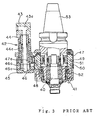
- a cutting (grinding) coolant is ejected over a machining part from a cutting (grinding) coolant nozzle 41 when a cutting (grinding) operation is performed with the use of a tool (not shown) attached to a distal end portion of a rotary shaft 40.
- the cutting (grinding) coolant is supplied to a first communication channel 48 through a supply port 43a of a rotation stopper block 43 of a rotation stopper 42, a center channel 44a of a rotation stopper pin 44, a hollow portion 45a of a guide sleeve 45, a communication channel 46a of a leg 46 and a communication channel 47a of a jacket cover 47.
- the cutting (grinding) coolant is then supplied to the cutting (grinding) coolant nozzle 41 from the first communication channel 48 through a first circumferential channel 49, a second circumferential channel 50, a second communication channel 51 and a communication channel 52.
- the planetary roller speed-up gear mechanism can be cooled with the cutting (grinding) coolant.
- reference numeral 53 denotes a taper shank.
- the cooling recently has been achieved by supplying the cooling liquid and the like in a mist form, rather than a liquid, to the machining part. This method tends to eliminate accumulation of the cooling liquid in a machined recess and also a chipping phenomenon occurring due to sudden cooling.
- Japanese Unexamined Patent Publication No. 9-141537 (1997), for example, proposes a lubricant supplying apparatus and a lubricant supplying method for spraying a lubricant.
- the aforesaid methods and apparatus require an ejection nozzle, e.g., the cutting (grinding) coolant nozzle 41.
- an ejection nozzle e.g., the cutting (grinding) coolant nozzle 41.
- the rotation shaft 40 cannot sufficiently be cooled, because the cutting (grinding) coolant flows through the channels outside the rotation shaft.
- a spindle and the like incorporated in a machine tool cannot be cooled at all.
- a machining method which comprises the steps of: providing a machine tool which includes a rotation shaft rotatably supported by support means; causing compressed air and a liquid to separately pass through the inside of the support means into the rotation shaft; mixing the liquid with the compressed air within the rotation shaft so as to form the liquid into a mist; feeding the resulting mist along the outer periphery of the tool or through the inside of the tool to a distal end of a generally cylindrical tool fixed to the rotation shaft; and supplying the mist to a machining part from the distal end of the tool.
- a mist supplying apparatus which comprises: support means rotatably supporting a rotation shaft; a generally cylindrical tool detachably fixed to the rotation shaft; a compressed air channel and a liquid channel separately provided within the support means, the compressed air channel adapted to be supplied with compressed air from compressed air supply means, the liquid channel adapted to be supplied with a liquid from liquid supply means; the rotation shaft having a channel provided therein for separately receiving the compressed air supplied from the compressed air channel and the liquid supplied from the liquid channel to mix the liquid with the compressed air to form the liquid into a mist form, wherein the resulting mist is fed to a distal end of the tool along the outer periphery of the tool or through the inside of the tool to supply the mist to a machining part from the distal end of the tool.
- the machine tool provided includes the rotation shaft rotatably supported by the support means and, when the workpiece is machined, the compressed air and the liquid which are separately passed through the inside of the support means are separately supplied into the rotation shaft. After the liquid is mixed with the compressed air within the rotation shaft so as to be formed into a mist, the resulting mist is fed to the distal end of the generally cylindrical tool fixed to the rotation shaft by passing along the outer periphery of the tool or through the inside of the tool.
- the mist formed within the rotation shaft is fed toward the tool through the inside of the rotation shaft and then along the outer periphery of the tool or through the inside of the tool to the distal end of the tool, so as to be supplied to the machining part from the distal end of the tool in the inventive machining method. Therefore, the need for an ejection nozzle can be obviated, and thus the number of components can be reduced so as to facilitate inventory control and also to reduce the size of the machine tool. Since the compressed air and the liquid are supplied into the rotation shaft, the rotation shaft can be efficiently cooled from the inside thereof by employing a cooling water as the liquid. Thus, an excellent cooling effect can be provided. On the other hand, the mist supplying apparatus according to the present invention provides the same function and effect as the above described inventive machining method.
- machining part herein means, for example, a surface of the tool involved in a machining operation and a surface of a workpiece being machined.
- mist may be supplied to the distal end of a tool along the outer periphery of the tool as well as through the inside of the tool.
- a cooling effect and a lubricating effect can be simultaneously provided to the machining part.
- the inventive mist supplying apparatus is adapted to supply the mixture of the cooling liquid and the cutting liquid into the liquid channel, the same function and effect can be ensured.
- the cooling liquid and the cutting liquid are separately supplied as the liquid into the rotation shaft in the inventive machining method, the cooling liquid and the cutting liquid are not mixed until these liquids are introduced into the rotation shaft. Thus, any degradation in the quality of these liquids is suppressed.
- the cooling liquid and the cutting liquid are formed into a mist and then mixed with each other within the rotation shaft. Thus, the mixing of the cooling liquid and the cutting liquid is sufficiently carried out, thereby providing excellent cooling and lubricating effects.
- the inventive mist supplying apparatus includes a cooling liquid channel and a cutting liquid channel separately provided as the liquid channel and the apparatus is adapted to supply the cooling liquid to the cooling liquid channel from cooling liquid supply means and supply the cutting liquid to the cutting liquid channel from cutting liquid supply means, the same function and effect can be ensured.
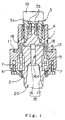
- Fig. 1 illustrates a mist supplying apparatus according to one embodiment of the present invention.
- a cylindrical casing 1 is vertically disposed and is adapted to be fixed to a machine tool such as a machining center (not shown).
- a rotation shaft 2 is vertically disposed within the casing 1.
- a topped cylindrical connection shaft 3 is fixed around an upper portion of the rotation shaft 2.
- the connection shaft 3 is rotatably supported within the casing 1 by an upper bearing 4 fixed to an upper portion of an inner peripheral surface of the casing 1, and the rotation shaft 2 is rotatably supported within the casing by a lower bearing 5 fixed to a lower portion of the inner peripheral surface of the casing.
- a cover 6 is removably fixed to a lower end face of the rotation shaft 2 by a plurality of fixing bolts 7 (only two of which are seen in Fig. 1).
- a compressed air channel 11 which receives compressed air supplied from compressed air supply means (not shown) having a motor, and a liquid channel 12, which receives a liquid (a mixture of a cooling water and a lubricating oil in this embodiment) supplied from liquid supply means (not shown) having a motor (which may double as the motor for the compressed air supply means), are separately provided in a peripheral wall of the casing 1.
- One end of the compressed air channel 11 opens into the inner periphery of the casing 1 between the upper and lower bearings 4 and 5.
- the other end of the compressed air channel 11 opens into the outer periphery of the casing 1 and is connected to the compressed air supply means via a pipe or the like (not shown).
- One end of the liquid channel 12 opens into the inner periphery of the casing 1 between the upper and lower bearings 4 and 5.
- the other end of the liquid channel 12 opens into the outer periphery of the casing 1 and is connected to the liquid supply means via a pipe or the like (not shown).
- the rotation shaft 2 has a single vertical hole 15 extending vertically and axially therethrough from the lower end face thereof.
- the vertical hole 15 includes an upper hole portion 16 having a threaded portion 16a provided on an inner peripheral surface thereof, and a lower hole portion (chuck portion) 17 which extends from a lower end of the upper hole portion to the lower end face of the rotation shaft 2 and which is flared downward.
- the rotation shaft 2 has a plurality of lateral holes 18 (two lateral holes 18 in this embodiment) which extend from an upper portion of the upper hole portion 16 perpendicularly to the axis thereof and open into the outer periphery thereof between the upper and lower bearings 4 and 5.
- the vertical hole 15 and the lateral holes 18 constitute an inner channel in the rotation shaft 2.
- An annular gap 8 is defined between the inner peripheral surface of the casing 1 and the outer peripheral surface of the rotation shaft 2.
- a connector 19 projects from an upper end face of the connection shaft 3, and is adapted to be coupled to rotation means such as a motor (not shown) via coupling means such as a belt (not shown).
- rotation means such as a motor (not shown)
- coupling means such as a belt (not shown).
- a plurality of fixing bolts 3b fix a top wall 3a of the connection shaft 3 to the upper end of the rotation shaft 2.
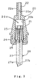
- a tool holder 20 includes a main portion 21, which is adapted to be removably inserted in the lower hole portion 17 of the vertical hole 15 of the rotation shaft 2 (see Fig. 1), and a connection rod 22 extending upright from an upper end face of the main portion 21.
- the connection rod 22 has a threaded portion 22a provided on an outer peripheral surface thereof which is adapted to be threadingly engaged with the threaded portion 16a of the upper hole portion 16 of the vertical hole 15 of the apparatus of Fig. 1.
- the tool holder 20 has a through-hole 20c extending axially therethrough which includes an upper small-diameter portion 20a extending through the connection rod 22 and a lower large-diameter portion 20b extending through the main portion 21 from a lower end face of the main portion 21.
- the connection rod 22 of the tool holder 20 threadingly engages the upper hole portion 16 of the rotation shaft 2 of the apparatus of Fig. 1, so that the upper hole portion 16 of the rotation shaft 2 and the through-hole 20c of the tool holder 20 are connected in series with the main portion 21 being inserted in the lower hole portion 17 of the rotation shaft 2.
- the tool is detachably fixed to a lower end of the tool holder by a collet 23, a clamp nut 24 and a cap 25.
- the tool 26 has a bifurcated channel 27 extending downward from an upper end thereof with one branch channel 27a opening into a rake face of the tool 26 and with the other branch channel 27b opening into a flank of the tool.
- a minute gap which permits passage of a mist mixture as will be described later is defined between an outer peripheral surface of the tool 26 and inner peripheral surfaces of the collet 23, the clamp nut 24 and the cap 25.
- the compressed air and the liquid are respectively supplied into the compressed air channel 11 and the liquid channel 12 of the casing 1 upon the actuation of the motors of the compressed air supply means and the liquid supply means, and respectively pass through the compressed air channel 11 and the liquid channel 12 so as to be introduced into the lateral holes 18 of the rotating rotation shaft 2 via the gap 8.
- the compressed air introduced into one of the lateral holes 18 and the liquid introduced into the other lateral hole 18 collide with each other so as to be mixed together in the upper hole portion 16 of the vertical hole 15 and the liquid is atomized into the form of a mist mixture.
- the resulting mist mixture flows through the upper hole portion 16 of the vertical hole 15 and the upper small-diameter portion 20a and the lower great-diameter portion 20b of the tool holder 20. Most of the mist mixture flows into the channels 27, 27a, 27b of the tool 26 so as to be ejected over the machining part. The remainder of the mist mixture (which has not flowed into the channels 27, 27a, 27b of the tool 26) flows into the minute gap between the outer peripheral surface of the tool 26 and the inner peripheral surfaces of the collet 23, the clamp nut 24 and the cap 25, and then is ejected from this minute gap along the outer periphery of the tool.
- the need for an ejection nozzle is obviated, thereby correspondingly reducing the number of the components and the size of the apparatus.
- the liquid (the mixture of the cooling water and the lubricating oil) is supplied into the rotation shaft 2, so that the rotation shaft can be efficiently cooled from the interior thereof.
- the mist mixture is ejected from the minute gap between the outer peripheral surface of the tool 26 and the inner peripheral surfaces of the collet 23, the fixing nut 24 and the cap 25 along the outer periphery of the tool 26. This makes it possible to protect a shoulder of the tool 26 (e.g., a drill).
- the tool 26 to be employed is formed with the channels 27, 27a, 27b in the aforesaid embodiment, the construction of the tool is not limited thereto, and a tool formed with none of the channels 27, 27a, 27b may be employed.
- a tool formed with none of the channels 27, 27a, 27b may be employed.
- the mist mixture ejected from the minute gap between the outer peripheral surface of the tool 26 and the inner peripheral surfaces of the collet 23, the clamp nut 24 and the cap 25 along the outer periphery of the tool 26 is supplied to the machining part.
- the cooling effect and the lubricating effect significantly vary depending on the type of the mist, it is preferred to control the mixing ratio between the cooling water and the cutting liquid (lubricating oil) by varying the supply amounts of the cooling water and the cutting liquid introduced into the liquid channel 12, and also to control the pressure of the compressed air supplied into the compressed air channel 11 and the pressure of the cooling water and the cutting liquid supplied into the liquid channel 12.
- the supply amount of the cooling water may be increased to increase the ratio of the cooling water to the cutting liquid for enhancement of the cooling effect.
- the supply amount of the cutting liquid may be increased to increase the ratio of the cutting liquid for enhancement of the lubricating effect.
- the cooling water is not limited thereto, and other examples of suitable cooling water include pure water and ultra-pure water.
- suitable cooling water include pure water and ultra-pure water.
- Bluebe #LB-1 may be employed or, alternatively, any of various ordinary cutting liquids may be employed.
- the cooling water and the cutting liquid are employed as the liquid in the aforesaid embodiment, the liquid may be selected from various types of liquids such as emulsions and chemical agents.
- the apparatus according to the present invention can be installed not only in the machining center for machining as in the aforesaid embodiment but also in various machine tools such as numerically controlled (NC) lathes and grinding machines.
- CNC numerically controlled
- the mist generated within the rotation shaft is fed toward the tool through the inside of the rotation shaft, then along the outer periphery of the tool or through the inside of the tool to the distal end of the tool, and then be supplied to a machining part from the distal end of the tool. Therefore, the need for an ejection nozzle can be obviated, whereby the number of the components can correspondingly be reduced so as to facilitate inventory control and also to reduce the size of the machine tool. Since compressed air and liquid are supplied into the rotation shaft, the rotation shaft can be efficiently cooled from the inside thereof by employing cooling water as the liquid. Thus, an excellent cooling effect can be provided. Additionally, the mist supplying apparatus according to the present invention provides the same function and effect as the inventive machining method.
- the cooling effect and the lubricating effect can be provided simultaneously to the machining part.
- the inventive mist supplying apparatus is adapted to supply the mixture of the cooling liquid and the cutting liquid into the liquid channel, the same function and effect can be ensured.
- the cooling liquid and the cutting liquid are separately supplied as the liquid into the rotation shaft in the inventive machining method, the cooling liquid and the cutting liquid are not mixed until these liquids are introduced into the rotation shaft, so that degradation in the quality of these liquids is suppressed.
- the cooling liquid and the cutting liquid are formed into a mist and then mixed with each other within the rotation shaft.
- the mixing of the cooling liquid and the cutting liquid is sufficiently carried out, thereby providing excellent cooling and lubricating effects.
- the inventive mist supplying apparatus includes a cooling liquid channel and a cutting liquid channel separately provided as the liquid channel and the cooling liquid to the cooling liquid channel is adapted to be supplied from cooling liquid supply means and supply the cutting liquid to the cutting liquid channel is adapted to be supplied from cutting liquid supply means, the same function and effect can be ensured.
Landscapes
- Engineering & Computer Science (AREA)
- Mechanical Engineering (AREA)
- Physics & Mathematics (AREA)
- Fluid Mechanics (AREA)
- Auxiliary Devices For Machine Tools (AREA)
Applications Claiming Priority (2)
| Application Number | Priority Date | Filing Date | Title |
|---|---|---|---|
| JP2001010729A JP2002210630A (ja) | 2001-01-18 | 2001-01-18 | 工作加工方法およびそれに用いる霧状体供給装置 |
| JP2001010729 | 2001-01-18 |
Publications (1)
| Publication Number | Publication Date |
|---|---|
| EP1225005A1 true EP1225005A1 (de) | 2002-07-24 |
Family
ID=18877992
Family Applications (1)
| Application Number | Title | Priority Date | Filing Date |
|---|---|---|---|
| EP02001345A Withdrawn EP1225005A1 (de) | 2001-01-18 | 2002-01-18 | Bearbeitungsverfahren und Vorrichtung zur Erzeugung von Nebel zur Durchführung des Verfahrens |
Country Status (3)
| Country | Link |
|---|---|
| US (1) | US20020119019A1 (de) |
| EP (1) | EP1225005A1 (de) |
| JP (1) | JP2002210630A (de) |
Cited By (1)
| Publication number | Priority date | Publication date | Assignee | Title |
|---|---|---|---|---|
| WO2010012933A3 (fr) * | 2008-07-30 | 2010-03-25 | European Aeronautic Defence And Space Company Eads France | Porte outils comportant des moyens de refroidissement a tube vortex |
Families Citing this family (8)
| Publication number | Priority date | Publication date | Assignee | Title |
|---|---|---|---|---|
| JP2002172539A (ja) * | 2000-12-07 | 2002-06-18 | Ekoregu:Kk | 工作加工方法およびそれに用いる霧状体供給装置 |
| GB0213019D0 (en) * | 2002-06-06 | 2002-07-17 | Clark John | Drilling attachment |
| JP2004136419A (ja) * | 2002-10-21 | 2004-05-13 | Daido Metal Co Ltd | 工作機械装置 |
| JP2005144565A (ja) * | 2003-11-11 | 2005-06-09 | Makino J Kk | 深穴加工方法及び装置 |
| JP4609893B2 (ja) * | 2006-02-02 | 2011-01-12 | 大同メタル工業株式会社 | 工具ホルダー |
| JP5389584B2 (ja) * | 2009-09-24 | 2014-01-15 | 富士重工業株式会社 | 回転切削装置 |
| GB0918978D0 (en) * | 2009-10-28 | 2009-12-16 | Gregory Jason N | Coolant adapter for cutting tools |
| KR101592348B1 (ko) * | 2014-10-02 | 2016-02-15 | 한국생산기술연구원 | 유체 혼합공급장치 |
Citations (13)
| Publication number | Priority date | Publication date | Assignee | Title |
|---|---|---|---|---|
| GB1238804A (de) * | 1968-06-06 | 1971-07-14 | ||
| SU1433777A1 (ru) * | 1987-03-10 | 1988-10-30 | Предприятие П/Я М-5120 | Способ подачи смазочно-охлаждающей жидкости в зону резани |
| DE4208063A1 (de) * | 1992-03-13 | 1993-09-16 | Hans Trinkaus | Vorrichtung zur aufgabe von kuehl- und/oder schmiermittel |
| JPH08112731A (ja) * | 1994-10-18 | 1996-05-07 | M S T Corp:Kk | 工具ホルダ |
| US5676506A (en) * | 1995-08-30 | 1997-10-14 | Horkos Corp. | Spindle device for machine tools |
| DE19725343A1 (de) * | 1996-09-26 | 1998-04-02 | Bielomatik Leuze & Co | Spindelkopf für Werkzeugmaschinen o. dgl. |
| EP0860231A1 (de) * | 1997-02-21 | 1998-08-26 | Gat Gesellschaft für Antriebstechnik mbH | Verfahren und Vorrichtung für die Zufuhr einer Fluidmischung in ein drehendes Maschinenteil |
| JPH10337632A (ja) * | 1997-06-09 | 1998-12-22 | Wako Giken Kogyo Kk | 切削液・切削気体の供給装置 |
| JPH11235641A (ja) * | 1998-02-20 | 1999-08-31 | Hookosu Kk | 工作機械の主軸装置 |
| DE19815134A1 (de) * | 1998-04-01 | 1999-10-14 | Bielomatik Leuze & Co | Spindelkopf für Werkzeugmaschinen o. dgl. |
| EP0978350A1 (de) * | 1998-01-23 | 2000-02-09 | Horkos Corp | Vorrichtung für die hauptspindel einer werkzeugmaschine und mehrspindelkopf für werkzeugmaschinen |
| EP0988927A2 (de) * | 1998-09-08 | 2000-03-29 | Ecoreg Ltd. | Verfahren zum Bearbeiten eines Werkstücks und Vorrichtung zur Erzeugung von darin verwendetem Nebel |
| EP1129815A2 (de) * | 2000-02-22 | 2001-09-05 | Ecoreg Ltd. | Bearbeitungsverfahren und Vorrichtung zur Erzeugung von Nebel zur Durchführung des Verfahrens |
-
2001
- 2001-01-18 JP JP2001010729A patent/JP2002210630A/ja active Pending
-
2002
- 2002-01-18 US US10/051,748 patent/US20020119019A1/en not_active Abandoned
- 2002-01-18 EP EP02001345A patent/EP1225005A1/de not_active Withdrawn
Patent Citations (13)
| Publication number | Priority date | Publication date | Assignee | Title |
|---|---|---|---|---|
| GB1238804A (de) * | 1968-06-06 | 1971-07-14 | ||
| SU1433777A1 (ru) * | 1987-03-10 | 1988-10-30 | Предприятие П/Я М-5120 | Способ подачи смазочно-охлаждающей жидкости в зону резани |
| DE4208063A1 (de) * | 1992-03-13 | 1993-09-16 | Hans Trinkaus | Vorrichtung zur aufgabe von kuehl- und/oder schmiermittel |
| JPH08112731A (ja) * | 1994-10-18 | 1996-05-07 | M S T Corp:Kk | 工具ホルダ |
| US5676506A (en) * | 1995-08-30 | 1997-10-14 | Horkos Corp. | Spindle device for machine tools |
| DE19725343A1 (de) * | 1996-09-26 | 1998-04-02 | Bielomatik Leuze & Co | Spindelkopf für Werkzeugmaschinen o. dgl. |
| EP0860231A1 (de) * | 1997-02-21 | 1998-08-26 | Gat Gesellschaft für Antriebstechnik mbH | Verfahren und Vorrichtung für die Zufuhr einer Fluidmischung in ein drehendes Maschinenteil |
| JPH10337632A (ja) * | 1997-06-09 | 1998-12-22 | Wako Giken Kogyo Kk | 切削液・切削気体の供給装置 |
| EP0978350A1 (de) * | 1998-01-23 | 2000-02-09 | Horkos Corp | Vorrichtung für die hauptspindel einer werkzeugmaschine und mehrspindelkopf für werkzeugmaschinen |
| JPH11235641A (ja) * | 1998-02-20 | 1999-08-31 | Hookosu Kk | 工作機械の主軸装置 |
| DE19815134A1 (de) * | 1998-04-01 | 1999-10-14 | Bielomatik Leuze & Co | Spindelkopf für Werkzeugmaschinen o. dgl. |
| EP0988927A2 (de) * | 1998-09-08 | 2000-03-29 | Ecoreg Ltd. | Verfahren zum Bearbeiten eines Werkstücks und Vorrichtung zur Erzeugung von darin verwendetem Nebel |
| EP1129815A2 (de) * | 2000-02-22 | 2001-09-05 | Ecoreg Ltd. | Bearbeitungsverfahren und Vorrichtung zur Erzeugung von Nebel zur Durchführung des Verfahrens |
Non-Patent Citations (4)
| Title |
|---|
| DATABASE WPI Section PQ Week 198918, Derwent World Patents Index; Class P56, AN 1989-136473, XP002196913 * |
| PATENT ABSTRACTS OF JAPAN vol. 1996, no. 09 30 September 1996 (1996-09-30) * |
| PATENT ABSTRACTS OF JAPAN vol. 1999, no. 03 31 March 1999 (1999-03-31) * |
| PATENT ABSTRACTS OF JAPAN vol. 1999, no. 13 30 November 1999 (1999-11-30) * |
Cited By (2)
| Publication number | Priority date | Publication date | Assignee | Title |
|---|---|---|---|---|
| WO2010012933A3 (fr) * | 2008-07-30 | 2010-03-25 | European Aeronautic Defence And Space Company Eads France | Porte outils comportant des moyens de refroidissement a tube vortex |
| US8876447B2 (en) | 2008-07-30 | 2014-11-04 | European Aeronautic Defence & Space Company | Tool holder comprising a cooling means |
Also Published As
| Publication number | Publication date |
|---|---|
| JP2002210630A (ja) | 2002-07-30 |
| US20020119019A1 (en) | 2002-08-29 |
Similar Documents
| Publication | Publication Date | Title |
|---|---|---|
| US6123270A (en) | Work machining method and apparatus for supplying mist used therein | |
| US6602031B2 (en) | Machining method and mist supplying apparatus | |
| EP2116326B1 (de) | Werkzeughalter für Spindelvorrichtung einer Werkzeugmaschine | |
| KR100217283B1 (ko) | 공작기계의 주축장치 | |
| EP0579371A1 (de) | Ein Verfahren und ein Gerät zum Bearbeiten eines Werkstückes | |
| CN1668420B (zh) | 机床的工具架 | |
| US5351376A (en) | Machine tool | |
| WO2012101751A1 (ja) | 工具ホルダ及び工作機械 | |
| EP1190814A1 (de) | Bearbeitungsverfahren und Nebelzuführapparat zum Vorrichtung zur Erzeugung von Nebel zur Durchführung des Verfahrens | |
| US20020119019A1 (en) | Machining method and mist supplying apparatus for use in the method | |
| US4726717A (en) | Deep-bore drilling machine | |
| US4693646A (en) | Apparatus for lubricating a workpiece | |
| KR20030031844A (ko) | 공구와 공구홀더 및 공작기계 | |
| US6793395B1 (en) | Bearing arrangement for machine tool spindles | |
| US7509719B2 (en) | Method and device for lubricating bearing positions, especially in machine tools or their parts | |
| EP0978350B1 (de) | Vorrichtung für die hauptspindel einer werkzeugmaschine und mehrspindelkopf für werkzeugmaschinen | |
| JPH11235641A (ja) | 工作機械の主軸装置 | |
| JPH08197371A (ja) | 工作機械の切粉気流除去装置 | |
| US20020085889A1 (en) | Machining method and mist supplying apparatus for use in the method | |
| JP2015033731A (ja) | ツールホルダ | |
| EP1205278A1 (de) | Kühlvorrichtung für eine Werkzeugmaschine | |
| KR100503175B1 (ko) | 공작기계의 주축장치 | |
| EP0988927A2 (de) | Verfahren zum Bearbeiten eines Werkstücks und Vorrichtung zur Erzeugung von darin verwendetem Nebel | |
| KR20190060084A (ko) | 공작기계 주축 사이드 절삭유 분사 시스템 | |
| KR102657943B1 (ko) | 비 중공축 절삭공구를 위한 듀얼채널 내부분사모듈 |
Legal Events
| Date | Code | Title | Description |
|---|---|---|---|
| PUAI | Public reference made under article 153(3) epc to a published international application that has entered the european phase |
Free format text: ORIGINAL CODE: 0009012 |
|
| AK | Designated contracting states |
Kind code of ref document: A1 Designated state(s): AT BE CH CY DE DK ES FI FR GB GR IE IT LI LU MC NL PT SE TR |
|
| AX | Request for extension of the european patent |
Free format text: AL;LT;LV;MK;RO;SI |
|
| AKX | Designation fees paid |
Designated state(s): BE CH DE FR GB LI SE |
|
| STAA | Information on the status of an ep patent application or granted ep patent |
Free format text: STATUS: THE APPLICATION IS DEEMED TO BE WITHDRAWN |
|
| 18D | Application deemed to be withdrawn |
Effective date: 20030125 |