EP0989585A2 - Dispositif de couplage d'une source d'ions à un spectromètre de masse - Google Patents
Dispositif de couplage d'une source d'ions à un spectromètre de masse Download PDFInfo
- Publication number
- EP0989585A2 EP0989585A2 EP99307233A EP99307233A EP0989585A2 EP 0989585 A2 EP0989585 A2 EP 0989585A2 EP 99307233 A EP99307233 A EP 99307233A EP 99307233 A EP99307233 A EP 99307233A EP 0989585 A2 EP0989585 A2 EP 0989585A2
- Authority
- EP
- European Patent Office
- Prior art keywords
- capillary
- orifice
- passage
- ion
- adaptor
- Prior art date
- Legal status (The legal status is an assumption and is not a legal conclusion. Google has not performed a legal analysis and makes no representation as to the accuracy of the status listed.)
- Granted
Links
- 230000008878 coupling Effects 0.000 title description 6
- 238000010168 coupling process Methods 0.000 title description 6
- 238000005859 coupling reaction Methods 0.000 title description 6
- 150000002500 ions Chemical class 0.000 claims abstract description 74
- 230000005540 biological transmission Effects 0.000 claims abstract description 15
- 239000000463 material Substances 0.000 claims description 12
- 239000007788 liquid Substances 0.000 claims description 7
- 239000012530 fluid Substances 0.000 claims 2
- 238000005070 sampling Methods 0.000 description 10
- 239000007921 spray Substances 0.000 description 5
- 150000003839 salts Chemical group 0.000 description 4
- 239000000523 sample Substances 0.000 description 4
- 239000000872 buffer Substances 0.000 description 2
- 230000008021 deposition Effects 0.000 description 2
- 230000001133 acceleration Effects 0.000 description 1
- 239000011248 coating agent Substances 0.000 description 1
- 238000000576 coating method Methods 0.000 description 1
- 238000011109 contamination Methods 0.000 description 1
- 238000003795 desorption Methods 0.000 description 1
- 238000010884 ion-beam technique Methods 0.000 description 1
- 238000001819 mass spectrum Methods 0.000 description 1
- 230000007935 neutral effect Effects 0.000 description 1
- 239000000615 nonconductor Substances 0.000 description 1
- 239000002245 particle Substances 0.000 description 1
- 239000012723 sample buffer Substances 0.000 description 1
- 239000002904 solvent Substances 0.000 description 1
Images


Classifications
-
- H—ELECTRICITY
- H01—ELECTRIC ELEMENTS
- H01J—ELECTRIC DISCHARGE TUBES OR DISCHARGE LAMPS
- H01J49/00—Particle spectrometers or separator tubes
- H01J49/02—Details
- H01J49/04—Arrangements for introducing or extracting samples to be analysed, e.g. vacuum locks; Arrangements for external adjustment of electron- or ion-optical components
- H01J49/0431—Arrangements for introducing or extracting samples to be analysed, e.g. vacuum locks; Arrangements for external adjustment of electron- or ion-optical components for liquid samples
- H01J49/044—Arrangements for introducing or extracting samples to be analysed, e.g. vacuum locks; Arrangements for external adjustment of electron- or ion-optical components for liquid samples with means for preventing droplets from entering the analyzer; Desolvation of droplets
Definitions
- This invention relates generally to an atmospheric pressure ion source connected to a mass analyzer by an ion transfer assembly which includes a capillary passage, and more particularly to a capillary having a sample orifice which is not in the line of sight of the ion source.
- U.S. Patent 5,157,260 shows a quadrupole mass filter coupled to an atmospheric pressure ion source by an ion transmission arrangement including a capillary, a conical skimmer and ion optics.
- a tube lens cooperates with the end of the capillary to force the ions into the center of the ion jet which travels through the conical skimmer.
- a quadrupole mass filter analyzes the transmitted ion beam to provide a mass spectrum.
- U.S. Patent No. 4,542,293 describes a capillary made of an electrical insulator for conducting ions out of the ionizing electrospray region at atmospheric pressure to a lower pressure region.
- a conductive coating is formed on the ends of the capillary and a voltage is applied thereacross to accelerate the ions.
- a skimmer is disposed adjacent the end of the capillary and is maintained at a voltage which causes further acceleration of the ions through the skimmer and into a lower pressure region which includes focusing lenses and analyzing apparatus.
- the orifice of the capillary passage which connects the atmospheric pressure chamber to a lower pressure chamber is in line with the outlet of the ion spray device which forms the sample ions for analysis.
- This arrangement provides excellent performance for the majority of solvent systems and flow regimes used in atmospheric pressure ion (API) analysis.
- API atmospheric pressure ion
- non-volatile buffer systems there is the possibility of fouling of the capillary intake or sampling orifice by deposition of salts from undesolvated droplets that strike the sampling orifice and evaporate.
- the deposited salts gradually block the flow of sample ions and reduce performance of the overall system by progressively reducing the number of ions which are transmitted to the mass analyzer.
- a ion transmission assembly which couples an atmospheric pressure ion source to a mass analyzer by an assembly including a capillary having a sampling orifice opposite the ion source and an adaptor mounted on the sampling end of the capillary for indirectly coupling the orifice to the ion source output.
- an atmospheric pressure ion source 11 is schematically shown coupled to a mass analyzer 12 by an ion transmission assembly.
- the ion source may comprise an electrospray ion source or corona discharge ion source.
- the ion source forms an ion spray 13.
- the ionization mechanism involves the desorption at atmospheric pressure of ions from the fine electrically charged particles formed by an electrospray source or a corona discharge source.
- the ion spray 13 may include undesolvated droplets particularly when non-volatile sample buffers are used.
- the ion transmission assembly includes successive chambers 16, 17 and 18, maintained at successively lower pressures, with the mass analyzer 12 in the lowest pressure chamber.
- the first chamber 16 communicates with the atmospheric pressure ionization chamber 21 via a capillary tube 22. Due to the differences in pressure, ions and gas are caused to enter the orifice 23 of the capillary tube, and flow through the capillary passage into the chamber 16.
- a voltage is applied between conductive sleeves 24 and 26 at the ends of the non-conducting capillary tube to provide a voltage gradient which accelerates the charged ions.
- the other end of the capillary is opposite a skimmer 31 which separates the chamber 16 from the chamber 17 which houses octopole lens 32.
- the skimmer includes a central orifice or aperture 33 which may be aligned with the axis of the bore of the capillary, or the capillary bore may be slightly off axis to reduce neutral noise as described in U.S. Patent No. RE 35,413.
- a tube lens 36 cooperates with the end of the capillary to force ions into the center of the ion jet which leaves the capillary and travels through the skimmer 31.
- the octopole lens 32 is followed by ion optics which may comprise a second skimmer 34 and lens 35, which direct ions into the analyzing chamber 18 and into a suitable mass analyzer 12.
- ion optics which may comprise a second skimmer 34 and lens 35, which direct ions into the analyzing chamber 18 and into a suitable mass analyzer 12.
- the combination of capillary tube 22, skimmer 31, lens 32, skimmer 34 and lens 35 form the ion transmission assembly.
- the entry orifice 23 of the capillary passage may be fouled by the deposition of salts from spray droplets and involatile material which strike the entrance orifice of the capillary and evaporate.
- the fouling is minimized in the present invention by indirectly coupling the sampling orifice to the ion source output so that it is no longer in the line of sight of the liquid droplets and involatile materials from the ion spray 13.
- An adaptor placed at the sampling end of the capillary prevents direct entry of the droplets and involatile material into the entrance orifice.
- the adaptor located at the entrance end of the capillary enables the indirect flow of ions into the sampling orifice. That is the orifice is not in direct line of sight of the ion source.
- the preferred embodiment shown in Figures 2-4 includes an adaptor 41 which supports a disk 42 opposite the capillary orifice 23.
- the disk prevents line of sight liquid and involatile material from impinging directly on the orifice. Consequently, sample ions are indirectly coupled from the ion source to the capillary orifice 23.
- the adaptor 41 includes a collar 43 which is inserted over the end of the capillary. The end of the collar 43 engages the cup-shaped support 44. Suitable support means such as screws 46,47 engage and support the disk 42.
- the bottom of the cup-shaped support 44 includes slots 48 which allow the liquid droplets and involatile materials to be diverted away or past the orifice 23.
- the desolvated ions pass around the outer edges of the disk 42 and into the axial capillary passages as a result of the pressure differential between the atmospheric chamber 21 and the lower pressure chamber 16.
- the adaptor prevents liquid droplets and involatile material build-up a the orifice 23.
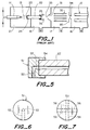
- Figures 5 and 6 show a disk-shaped adaptor 51 which has a radial passage 52 which terminates in an axial passage 53.
- the adaptor is suitably secured to the end of the capillary tube 22 by collar 54. This prevents liquid droplets from directly entering the capillary passage, but permits ions and gas to be sucked into the input orifice 23 of the capillary 22 through the passages 52, 53.
- Figure 7 shows an adaptor with four radial passages 56 providing a greater flow of ions into the capillary 22.
- Figures 8 and 9 show an adaptor 57 which includes a slot 58 forming radial passages when the adaptor is secured to the capillary 22.
- Figure 10 shows an adaptor 49 with a bent tube 61 which provides flow of ions to the capillary 22.
- the embodiments of Figures 5-10 all prevent direct entry of droplets and involatile material into the capillary orifice 25.
- the adaptor may be used when needed without requiring the replacement of the capillary in mass analysis systems which are normally used with samples having volatile buffers. Furthermore, the adaptors can be replaced if contamination does occur, rather than having to replace the whole heated capillary.
- an ion transmission system including a capillary and an adaptor which prevents direct line of sight between the ion source and the capillary orifice, whereby the capillary orifice is not fouled by deposited salts from evaporated liquid droplets or involatile material from the ion source.
Landscapes
- Chemical & Material Sciences (AREA)
- Analytical Chemistry (AREA)
- Electron Tubes For Measurement (AREA)
- Other Investigation Or Analysis Of Materials By Electrical Means (AREA)
Applications Claiming Priority (2)
| Application Number | Priority Date | Filing Date | Title |
|---|---|---|---|
| US160502 | 1998-09-24 | ||
| US09/160,502 US6248999B1 (en) | 1998-09-24 | 1998-09-24 | Assembly for coupling an ion source to a mass analyzer |
Publications (3)
| Publication Number | Publication Date |
|---|---|
| EP0989585A2 true EP0989585A2 (fr) | 2000-03-29 |
| EP0989585A3 EP0989585A3 (fr) | 2005-10-05 |
| EP0989585B1 EP0989585B1 (fr) | 2007-08-15 |
Family
ID=22577131
Family Applications (1)
| Application Number | Title | Priority Date | Filing Date |
|---|---|---|---|
| EP99307233A Expired - Lifetime EP0989585B1 (fr) | 1998-09-24 | 1999-09-13 | Dispositif de couplage d'une source d'ions à un spectromètre de masse |
Country Status (5)
| Country | Link |
|---|---|
| US (1) | US6248999B1 (fr) |
| EP (1) | EP0989585B1 (fr) |
| JP (1) | JP2000106126A (fr) |
| CA (1) | CA2282784C (fr) |
| DE (1) | DE69936829T2 (fr) |
Cited By (3)
| Publication number | Priority date | Publication date | Assignee | Title |
|---|---|---|---|---|
| GB2346730A (en) * | 1999-02-11 | 2000-08-16 | Masslab Limited | Ion source for mass analyser |
| EP2912677A4 (fr) * | 2012-10-28 | 2016-08-10 | Perkinelmer Health Sci Inc | Adaptateurs pour dispositif d'analyse directe d'échantillons et leurs procédés d'utilisation |
| EP3518273A4 (fr) * | 2016-09-21 | 2020-04-22 | Human Metabolome Technologies, Inc. | Adaptateur de source d'ions |
Families Citing this family (4)
| Publication number | Priority date | Publication date | Assignee | Title |
|---|---|---|---|---|
| US7015466B2 (en) * | 2003-07-24 | 2006-03-21 | Purdue Research Foundation | Electrosonic spray ionization method and device for the atmospheric ionization of molecules |
| US7351960B2 (en) * | 2005-05-16 | 2008-04-01 | Thermo Finnigan Llc | Enhanced ion desolvation for an ion mobility spectrometry device |
| EP1865533B1 (fr) * | 2006-06-08 | 2014-09-17 | Microsaic Systems PLC | Interface isolante micromécanique pour système d'ionisation |
| US9905409B2 (en) | 2007-11-30 | 2018-02-27 | Waters Technologies Corporation | Devices and methods for performing mass analysis |
Family Cites Families (7)
| Publication number | Priority date | Publication date | Assignee | Title |
|---|---|---|---|---|
| US4542293A (en) | 1983-04-20 | 1985-09-17 | Yale University | Process and apparatus for changing the energy of charged particles contained in a gaseous medium |
| US5157260A (en) | 1991-05-17 | 1992-10-20 | Finnian Corporation | Method and apparatus for focusing ions in viscous flow jet expansion region of an electrospray apparatus |
| US5565679A (en) * | 1993-05-11 | 1996-10-15 | Mds Health Group Limited | Method and apparatus for plasma mass analysis with reduced space charge effects |
| JP3087548B2 (ja) * | 1993-12-09 | 2000-09-11 | 株式会社日立製作所 | 液体クロマトグラフ結合型質量分析装置 |
| US5986259A (en) * | 1996-04-23 | 1999-11-16 | Hitachi, Ltd. | Mass spectrometer |
| US5869831A (en) * | 1996-06-27 | 1999-02-09 | Yale University | Method and apparatus for separation of ions in a gas for mass spectrometry |
| US5736741A (en) | 1996-07-30 | 1998-04-07 | Hewlett Packard Company | Ionization chamber and mass spectrometry system containing an easily removable and replaceable capillary |
-
1998
- 1998-09-24 US US09/160,502 patent/US6248999B1/en not_active Expired - Fee Related
-
1999
- 1999-09-13 EP EP99307233A patent/EP0989585B1/fr not_active Expired - Lifetime
- 1999-09-13 DE DE69936829T patent/DE69936829T2/de not_active Expired - Lifetime
- 1999-09-17 CA CA002282784A patent/CA2282784C/fr not_active Expired - Fee Related
- 1999-09-22 JP JP11267974A patent/JP2000106126A/ja active Pending
Cited By (6)
| Publication number | Priority date | Publication date | Assignee | Title |
|---|---|---|---|---|
| GB2346730A (en) * | 1999-02-11 | 2000-08-16 | Masslab Limited | Ion source for mass analyser |
| GB2346730B (en) * | 1999-02-11 | 2003-04-23 | Masslab Ltd | Ion source for mass analyser |
| US6700119B1 (en) | 1999-02-11 | 2004-03-02 | Thermo Finnigan Llc | Ion source for mass analyzer |
| EP2912677A4 (fr) * | 2012-10-28 | 2016-08-10 | Perkinelmer Health Sci Inc | Adaptateurs pour dispositif d'analyse directe d'échantillons et leurs procédés d'utilisation |
| EP3518273A4 (fr) * | 2016-09-21 | 2020-04-22 | Human Metabolome Technologies, Inc. | Adaptateur de source d'ions |
| US10734214B2 (en) | 2016-09-21 | 2020-08-04 | Human Metabolome Technologies, Inc. | Ion source adapter |
Also Published As
| Publication number | Publication date |
|---|---|
| EP0989585B1 (fr) | 2007-08-15 |
| JP2000106126A (ja) | 2000-04-11 |
| DE69936829T2 (de) | 2008-04-30 |
| DE69936829D1 (de) | 2007-09-27 |
| EP0989585A3 (fr) | 2005-10-05 |
| CA2282784C (fr) | 2002-04-09 |
| CA2282784A1 (fr) | 2000-03-24 |
| US6248999B1 (en) | 2001-06-19 |
Similar Documents
| Publication | Publication Date | Title |
|---|---|---|
| EP2218093B1 (fr) | Dispositif pour effectuer une analyse de masse | |
| US7098452B2 (en) | Atmospheric pressure charged particle discriminator for mass spectrometry | |
| US6278110B1 (en) | Orthogonal ion sampling for APCI mass spectrometry | |
| US5756994A (en) | Electrospray and atmospheric pressure chemical ionization mass spectrometer and ion source | |
| US5432343A (en) | Ion focusing lensing system for a mass spectrometer interfaced to an atmospheric pressure ion source | |
| US5495108A (en) | Orthogonal ion sampling for electrospray LC/MS | |
| USRE35413E (en) | Electrospray ion source with reduced neutral noise and method | |
| US5304798A (en) | Housing for converting an electrospray to an ion stream | |
| US7700913B2 (en) | Sampling system for use with surface ionization spectroscopy | |
| US4647772A (en) | Mass spectrometers | |
| US7687771B2 (en) | High sensitivity mass spectrometer interface for multiple ion sources | |
| US20040245458A1 (en) | Ion enrichment aperture arrays | |
| US20090090858A1 (en) | Sampling system for use with surface ionization spectroscopy | |
| JP2010537371A (ja) | 真空以上の圧力での試料のイオン化 | |
| EP3291281B1 (fr) | Méthode pour transférer des ions | |
| JP2002525821A (ja) | マススペクトロメータのためのイオン光学系 | |
| US5331159A (en) | Combined electrospray/particle beam liquid chromatography/mass spectrometer | |
| US6248999B1 (en) | Assembly for coupling an ion source to a mass analyzer | |
| JPH06138092A (ja) | パーティクルビーム液体クロマトグラフ・質量分析装置 | |
| US7368708B2 (en) | Apparatus for producing ions from an electrospray assembly | |
| JPH04218763A (ja) | 分析計へのイオン蒸気供給装置及び熱噴射イオン源 | |
| US12002672B2 (en) | Apparatus and methods for reduced neutral contamination in a mass spectrometer | |
| JPH08297112A (ja) | 液体クロマトグラフ質量分析装置 | |
| WO2000019193A1 (fr) | Dispositif d'electronebulisation a courant divergent pour spectrometrie de masse | |
| JPH1130606A (ja) | 液体クロマトグラフ質量分析装置 |
Legal Events
| Date | Code | Title | Description |
|---|---|---|---|
| PUAI | Public reference made under article 153(3) epc to a published international application that has entered the european phase |
Free format text: ORIGINAL CODE: 0009012 |
|
| AK | Designated contracting states |
Kind code of ref document: A2 Designated state(s): AT BE CH CY DE DK ES FI FR GB GR IE IT LI LU MC NL PT SE |
|
| AX | Request for extension of the european patent |
Free format text: AL;LT;LV;MK;RO;SI |
|
| RAP1 | Party data changed (applicant data changed or rights of an application transferred) |
Owner name: THERMO FINNIGAN LLC |
|
| RAP1 | Party data changed (applicant data changed or rights of an application transferred) |
Owner name: FINNIGAN CORPORATION |
|
| RAP1 | Party data changed (applicant data changed or rights of an application transferred) |
Owner name: THERMO FINNIGAN LLC |
|
| PUAL | Search report despatched |
Free format text: ORIGINAL CODE: 0009013 |
|
| AK | Designated contracting states |
Kind code of ref document: A3 Designated state(s): AT BE CH CY DE DK ES FI FR GB GR IE IT LI LU MC NL PT SE |
|
| AX | Request for extension of the european patent |
Extension state: AL LT LV MK RO SI |
|
| 17P | Request for examination filed |
Effective date: 20060313 |
|
| AKX | Designation fees paid |
Designated state(s): DE GB |
|
| GRAP | Despatch of communication of intention to grant a patent |
Free format text: ORIGINAL CODE: EPIDOSNIGR1 |
|
| GRAS | Grant fee paid |
Free format text: ORIGINAL CODE: EPIDOSNIGR3 |
|
| GRAA | (expected) grant |
Free format text: ORIGINAL CODE: 0009210 |
|
| RIN1 | Information on inventor provided before grant (corrected) |
Inventor name: TANG, KEGI Inventor name: MYLCHREEST, IAIN C. |
|
| AK | Designated contracting states |
Kind code of ref document: B1 Designated state(s): DE GB |
|
| REG | Reference to a national code |
Ref country code: GB Ref legal event code: FG4D |
|
| REF | Corresponds to: |
Ref document number: 69936829 Country of ref document: DE Date of ref document: 20070927 Kind code of ref document: P |
|
| PLBE | No opposition filed within time limit |
Free format text: ORIGINAL CODE: 0009261 |
|
| STAA | Information on the status of an ep patent application or granted ep patent |
Free format text: STATUS: NO OPPOSITION FILED WITHIN TIME LIMIT |
|
| 26N | No opposition filed |
Effective date: 20080516 |
|
| PGFP | Annual fee paid to national office [announced via postgrant information from national office to epo] |
Ref country code: DE Payment date: 20130919 Year of fee payment: 15 |
|
| PGFP | Annual fee paid to national office [announced via postgrant information from national office to epo] |
Ref country code: GB Payment date: 20130919 Year of fee payment: 15 |
|
| REG | Reference to a national code |
Ref country code: DE Ref legal event code: R119 Ref document number: 69936829 Country of ref document: DE |
|
| GBPC | Gb: european patent ceased through non-payment of renewal fee |
Effective date: 20140913 |
|
| PG25 | Lapsed in a contracting state [announced via postgrant information from national office to epo] |
Ref country code: GB Free format text: LAPSE BECAUSE OF NON-PAYMENT OF DUE FEES Effective date: 20140913 Ref country code: DE Free format text: LAPSE BECAUSE OF NON-PAYMENT OF DUE FEES Effective date: 20150401 |