EP0989646B1 - Zündkerze und Zündanordnung zur Anwendung in einem Verbrennungsmotor - Google Patents
Zündkerze und Zündanordnung zur Anwendung in einem Verbrennungsmotor Download PDFInfo
- Publication number
- EP0989646B1 EP0989646B1 EP19990307498 EP99307498A EP0989646B1 EP 0989646 B1 EP0989646 B1 EP 0989646B1 EP 19990307498 EP19990307498 EP 19990307498 EP 99307498 A EP99307498 A EP 99307498A EP 0989646 B1 EP0989646 B1 EP 0989646B1
- Authority
- EP
- European Patent Office
- Prior art keywords
- spark
- center electrode
- spark plug
- weight
- discharge
- Prior art date
- Legal status (The legal status is an assumption and is not a legal conclusion. Google has not performed a legal analysis and makes no representation as to the accuracy of the status listed.)
- Expired - Lifetime
Links
- 238000002485 combustion reaction Methods 0.000 title claims description 10
- 239000012212 insulator Substances 0.000 claims description 24
- 229910052751 metal Inorganic materials 0.000 claims description 22
- 239000002184 metal Substances 0.000 claims description 20
- 239000000463 material Substances 0.000 claims description 17
- 239000002131 composite material Substances 0.000 claims description 2
- 230000000737 periodic effect Effects 0.000 claims description 2
- 230000007704 transition Effects 0.000 description 24
- 239000000843 powder Substances 0.000 description 22
- 229910045601 alloy Inorganic materials 0.000 description 17
- 239000000956 alloy Substances 0.000 description 17
- 238000010891 electric arc Methods 0.000 description 17
- 238000012360 testing method Methods 0.000 description 17
- 239000011521 glass Substances 0.000 description 14
- 230000007423 decrease Effects 0.000 description 13
- 239000000203 mixture Substances 0.000 description 11
- 238000007254 oxidation reaction Methods 0.000 description 10
- BASFCYQUMIYNBI-UHFFFAOYSA-N platinum Substances [Pt] BASFCYQUMIYNBI-UHFFFAOYSA-N 0.000 description 10
- 230000000694 effects Effects 0.000 description 7
- 238000002844 melting Methods 0.000 description 7
- 230000008018 melting Effects 0.000 description 7
- 230000003647 oxidation Effects 0.000 description 7
- 238000003466 welding Methods 0.000 description 7
- 239000000446 fuel Substances 0.000 description 6
- GWEVSGVZZGPLCZ-UHFFFAOYSA-N Titan oxide Chemical compound O=[Ti]=O GWEVSGVZZGPLCZ-UHFFFAOYSA-N 0.000 description 4
- MCMNRKCIXSYSNV-UHFFFAOYSA-N Zirconium dioxide Chemical compound O=[Zr]=O MCMNRKCIXSYSNV-UHFFFAOYSA-N 0.000 description 4
- 238000011109 contamination Methods 0.000 description 4
- 230000003247 decreasing effect Effects 0.000 description 4
- 230000006735 deficit Effects 0.000 description 4
- 239000000919 ceramic Substances 0.000 description 3
- 238000002156 mixing Methods 0.000 description 3
- 229910001209 Low-carbon steel Inorganic materials 0.000 description 2
- 229910000990 Ni alloy Inorganic materials 0.000 description 2
- VYPSYNLAJGMNEJ-UHFFFAOYSA-N Silicium dioxide Chemical compound O=[Si]=O VYPSYNLAJGMNEJ-UHFFFAOYSA-N 0.000 description 2
- 239000011230 binding agent Substances 0.000 description 2
- 239000006229 carbon black Substances 0.000 description 2
- 229910052802 copper Inorganic materials 0.000 description 2
- 238000010586 diagram Methods 0.000 description 2
- 230000005611 electricity Effects 0.000 description 2
- 230000001771 impaired effect Effects 0.000 description 2
- 229910052741 iridium Inorganic materials 0.000 description 2
- 229910052742 iron Inorganic materials 0.000 description 2
- 238000005259 measurement Methods 0.000 description 2
- 229910052697 platinum Inorganic materials 0.000 description 2
- 238000009877 rendering Methods 0.000 description 2
- 238000005245 sintering Methods 0.000 description 2
- 239000000126 substance Substances 0.000 description 2
- 229910052718 tin Inorganic materials 0.000 description 2
- OYPRJOBELJOOCE-UHFFFAOYSA-N Calcium Chemical compound [Ca] OYPRJOBELJOOCE-UHFFFAOYSA-N 0.000 description 1
- OKTJSMMVPCPJKN-UHFFFAOYSA-N Carbon Chemical compound [C] OKTJSMMVPCPJKN-UHFFFAOYSA-N 0.000 description 1
- 229920001353 Dextrin Polymers 0.000 description 1
- 239000004375 Dextrin Substances 0.000 description 1
- 229910000575 Ir alloy Inorganic materials 0.000 description 1
- FUJCRWPEOMXPAD-UHFFFAOYSA-N Li2O Inorganic materials [Li+].[Li+].[O-2] FUJCRWPEOMXPAD-UHFFFAOYSA-N 0.000 description 1
- 229910004369 ThO2 Inorganic materials 0.000 description 1
- 230000002411 adverse Effects 0.000 description 1
- PNEYBMLMFCGWSK-UHFFFAOYSA-N aluminium oxide Inorganic materials [O-2].[O-2].[O-2].[Al+3].[Al+3] PNEYBMLMFCGWSK-UHFFFAOYSA-N 0.000 description 1
- 229910003481 amorphous carbon Inorganic materials 0.000 description 1
- 229910052787 antimony Inorganic materials 0.000 description 1
- 230000004323 axial length Effects 0.000 description 1
- 229910052791 calcium Inorganic materials 0.000 description 1
- 239000011575 calcium Substances 0.000 description 1
- 229910052799 carbon Inorganic materials 0.000 description 1
- 229910052681 coesite Inorganic materials 0.000 description 1
- PMHQVHHXPFUNSP-UHFFFAOYSA-M copper(1+);methylsulfanylmethane;bromide Chemical compound Br[Cu].CSC PMHQVHHXPFUNSP-UHFFFAOYSA-M 0.000 description 1
- 230000007797 corrosion Effects 0.000 description 1
- 238000005260 corrosion Methods 0.000 description 1
- 229910052906 cristobalite Inorganic materials 0.000 description 1
- 230000006866 deterioration Effects 0.000 description 1
- 235000019425 dextrin Nutrition 0.000 description 1
- XUCJHNOBJLKZNU-UHFFFAOYSA-M dilithium;hydroxide Chemical compound [Li+].[Li+].[OH-] XUCJHNOBJLKZNU-UHFFFAOYSA-M 0.000 description 1
- 238000010894 electron beam technology Methods 0.000 description 1
- 238000002474 experimental method Methods 0.000 description 1
- 238000010304 firing Methods 0.000 description 1
- 229910002804 graphite Inorganic materials 0.000 description 1
- 239000010439 graphite Substances 0.000 description 1
- 229910052735 hafnium Inorganic materials 0.000 description 1
- 238000010438 heat treatment Methods 0.000 description 1
- 238000007731 hot pressing Methods 0.000 description 1
- 229910001026 inconel Inorganic materials 0.000 description 1
- 229910001055 inconels 600 Inorganic materials 0.000 description 1
- 150000002484 inorganic compounds Chemical class 0.000 description 1
- 229910010272 inorganic material Inorganic materials 0.000 description 1
- 238000009413 insulation Methods 0.000 description 1
- GKOZUEZYRPOHIO-UHFFFAOYSA-N iridium atom Chemical compound [Ir] GKOZUEZYRPOHIO-UHFFFAOYSA-N 0.000 description 1
- MRELNEQAGSRDBK-UHFFFAOYSA-N lanthanum oxide Inorganic materials [O-2].[O-2].[O-2].[La+3].[La+3] MRELNEQAGSRDBK-UHFFFAOYSA-N 0.000 description 1
- 239000006123 lithium glass Substances 0.000 description 1
- 238000012423 maintenance Methods 0.000 description 1
- 150000002739 metals Chemical class 0.000 description 1
- 238000000034 method Methods 0.000 description 1
- 238000012986 modification Methods 0.000 description 1
- 230000004048 modification Effects 0.000 description 1
- 229910052759 nickel Inorganic materials 0.000 description 1
- KTUFCUMIWABKDW-UHFFFAOYSA-N oxo(oxolanthaniooxy)lanthanum Chemical compound O=[La]O[La]=O KTUFCUMIWABKDW-UHFFFAOYSA-N 0.000 description 1
- 238000007747 plating Methods 0.000 description 1
- 229910052761 rare earth metal Inorganic materials 0.000 description 1
- 150000002910 rare earth metals Chemical class 0.000 description 1
- 239000011369 resultant mixture Substances 0.000 description 1
- 230000035939 shock Effects 0.000 description 1
- 238000004904 shortening Methods 0.000 description 1
- 239000000377 silicon dioxide Substances 0.000 description 1
- 229910052709 silver Inorganic materials 0.000 description 1
- 239000002904 solvent Substances 0.000 description 1
- 239000004071 soot Substances 0.000 description 1
- 229910052682 stishovite Inorganic materials 0.000 description 1
- 230000001629 suppression Effects 0.000 description 1
- ZCUFMDLYAMJYST-UHFFFAOYSA-N thorium dioxide Chemical compound O=[Th]=O ZCUFMDLYAMJYST-UHFFFAOYSA-N 0.000 description 1
- 229910052719 titanium Inorganic materials 0.000 description 1
- 229910052905 tridymite Inorganic materials 0.000 description 1
- XLYOFNOQVPJJNP-UHFFFAOYSA-N water Substances O XLYOFNOQVPJJNP-UHFFFAOYSA-N 0.000 description 1
- 229910052725 zinc Inorganic materials 0.000 description 1
- 229910052726 zirconium Inorganic materials 0.000 description 1
Images


Classifications
-
- H—ELECTRICITY
- H01—ELECTRIC ELEMENTS
- H01T—SPARK GAPS; OVERVOLTAGE ARRESTERS USING SPARK GAPS; SPARKING PLUGS; CORONA DEVICES; GENERATING IONS TO BE INTRODUCED INTO NON-ENCLOSED GASES
- H01T13/00—Sparking plugs
- H01T13/20—Sparking plugs characterised by features of the electrodes or insulation
- H01T13/39—Selection of materials for electrodes
-
- H—ELECTRICITY
- H01—ELECTRIC ELEMENTS
- H01T—SPARK GAPS; OVERVOLTAGE ARRESTERS USING SPARK GAPS; SPARKING PLUGS; CORONA DEVICES; GENERATING IONS TO BE INTRODUCED INTO NON-ENCLOSED GASES
- H01T13/00—Sparking plugs
- H01T13/40—Sparking plugs structurally combined with other devices
- H01T13/41—Sparking plugs structurally combined with other devices with interference suppressing or shielding means
-
- F—MECHANICAL ENGINEERING; LIGHTING; HEATING; WEAPONS; BLASTING
- F02—COMBUSTION ENGINES; HOT-GAS OR COMBUSTION-PRODUCT ENGINE PLANTS
- F02B—INTERNAL-COMBUSTION PISTON ENGINES; COMBUSTION ENGINES IN GENERAL
- F02B2275/00—Other engines, components or details, not provided for in other groups of this subclass
- F02B2275/18—DOHC [Double overhead camshaft]
Definitions
- the present invention relates to a spark plug for use with an internal combustion engine and to an ignition system for use with an internal combustion engine having the spark plugs.
- an ignition system for use with an automotive internal combustion engine having spark plugs has conventionally employed a distributor.
- an ignition coil 251 includes a primary coil 252, which receives electricity from a battery 256 via an ignition switch 257 and is connected to an igniter 254, and a secondary coil 253, which is connected to a distributor 250.
- an electronic control unit 255 issues a break instruction signal to the igniter 254 at a predetermined firing timing
- the igniter 254 causes a contactless switch unit to operate so as to interrupt current flowing to the primary coil 252.
- a high-voltage current is induced in the secondary coil 253.
- the distributor 250 distributes the induced current to spark plugs 100 through high-tension cables C.
- the DLI system features easy control of ignition timing and does not require maintenance of contacts.
- an ignition coil is mounted directly on each spark plug.
- a control unit interrupts current flowing to the primary coil of the ignition coil of each spark plug at a predetermined timing to thereby fire the spark plug. Since ignition coils are mounted directly on the respective spark plugs, high-tension cables are not required.
- a chip of Pt (platinum) serving as a spark portion is formed at one end of an electrode of the spark plug.
- Pt platinum
- Ir iridium
- a spark portion of Ir produces a volatile oxide at a temperature of 900°C to 1000°C, indicating a tendency to be consumed within this temperature range.
- spark discharge of a spark plug is generally classified, according to form, into glow discharge and arc discharge.
- a glow discharge occurs, for example, when the impedance of a power source (hereinafter referred to as a "power-source impedance") is relatively high. Since a discharge current is relatively weak, the glow discharge causes a less severe temperature increase and less consumption of the spark portion. By contrast, an arc discharge often occurs when a power-source impedance is relatively low.
- glow discharge is desirably dominant in a spark discharge.
- the power-source impedance is high because of the electric resistances of a contact gap and a high-tension cable. Accordingly, glow discharge is dominant in a spark discharge.
- the power-source impedance is low, since the electric resistances of a contact gap and a high-tension cable are not present. Accordingly, depending on the material used for an electrode, the rate of transition from glow discharge to arc discharge increases in a spark discharge, potentially causing consumption of the electrode.
- a spark portion of an Ir-based material exhibits a particularly high rate of transition from glow discharge to arc discharge, potentially shortening spark plug life. This tendency is further accelerated by consumption of the spark portion caused by volatilization through oxidation.
- Japanese Patent Application Laid-Open No. 7-50192 (USP 5,514,929) which is considered to represent the closest prior art describes that when a spark plug with a tip mainly formed of Ir is used in a gas engine, the energy of induced discharge can be decreased by use of a resistor having a resistance not less than 50 k ⁇ but not greater than 200 k ⁇ .
- a gas engine would not have a problem in relation to ignitability even when the discharge energy decreases
- a gasoline engine would have a problem in relation to ignitability when the discharge energy decreases.
- a first object of the present invention is to provide a spark plug in which an arc discharge becomes unlikely to occur in spite of a spark portion being formed from an Ir-based metal, to thereby suppress consumption of an electrode and deterioration of ignitability.
- a second object of the present invention is to provide an ignition system for use with an internal combustion engine having the spark plugs.
- the present invention provides a spark plug comprising: a center electrode; an insulator which surrounds said center electrode; a metallic shell which surrounds said insulator; a ground electrode which faces said center electrode; a spark portion formed from a metal which contains not less than 60% by weight Ir fixedly attached to at least either one of said center electrode and said ground electrode to thereby define a spark discharge gap, a metallic terminal fixedly attached into one end portion of a through-hole formed axially in the insulator, the center electrode being fixedly attached into the other end portion of the through-hole; and a resistor disposed within the through-hole and between the metallic terminal and the center electrode characterised in that said resistor has an electric resistance of not less than 10 k ⁇ but not greater than 25 k ⁇ .
- the present invention provides an ignition system for use with an internal combustion engine comprising a spark plug and a coil unit, according to the features of claim 7.
- the spark plug comprises a center electrode; an insulator which surrounds the center electrode; a metallic shell which surrounds the insulator; a ground electrode which faces the center electrode; and a spark portion which is fixedly attached to at least either one of the center electrode and the ground electrode to thereby define a spark discharge gap.
- the spark portion is formed from a metal which contains not less than 60% by weight Ir.
- the spark plug further comprises a metallic terminal fixedly attached into one end portion of a through-hole formed axially in the insulator, the center electrode being fixedly attached into the other end portion of the through-hole.
- the coil unit comprises a casing attached to the spark plug; and an ignition coil accommodated within the casing and connected to the metallic terminal of the spark plug in order to apply a high voltage to the spark plug for effecting an electrical discharge.
- the ignition system further comprises a resistance portion disposed between the ignition coil and the center electrode so as to establish an electric resistance of not less than 10 k ⁇ but not greater than 25 k ⁇ between the ignition coil and the center electrode.
- the metal When the spark portion is formed from an Ir-based metal, the metal must contain Ir in an amount of not less than 60% by weight; otherwise, the high melting point of Ir fails to lead to sufficient improvement in resistance to spark consumption of the spark portion.
- a high Ir content of the spark portion tends to cause transition to a strong-current discharge, such as an arc discharge.
- the temperature of the spark portion increases to such a level that an Ir component volatilizes through oxidation, so that the spark portion is consumed accordingly.
- the present inventors conducted extensive studies and, as a result, found that even in the DLI system a spark plug whose spark portion is of the above-described Ir-based metal (hereinafter may be referred to as an "Ir-type plug") stably maintains an electrical discharge with a relatively weak current, such as a glow discharge, through establishment of an electric resistance of not less than 10 k ⁇ (corresponding to a power-source impedance) between the ignition coil and the center electrode.
- a relatively weak current such as a glow discharge
- electric resistance as measured between the ignition coil and the center electrode is preferably not less than 15 k ⁇ . However, if the electric resistance is in excess of 25 k ⁇ , ignitability may be impaired.
- a resistor incorporated in a spark plug and adapted to reduce radio noise.
- the electric resistance of the resistor may be increased such that an electric resistance of not less than 10 k ⁇ (preferably not less than 15 k ⁇ ) but not greater than 25 k ⁇ is established between the metallic terminal and the center electrode.
- a resistance portion such as a resistor, may be provided in the coil unit such that an electric resistance of the above-mentioned range is established between the ignition coil and the center electrode.
- the diameter of the end portion is preferably adjusted to not greater than 1.1 mm. By rendering the diameter of the end portion not greater than 1.1 mm, ignitability is improved significantly. More preferably, the diameter of the end portion is adjusted to 0.3 mm to 0.8 mm. By rendering the diameter of the end portion not greater than 0.8 mm, ignitability is further improved.
- the diameter of the end portion becomes less than 0.3 mm, the temperature of the spark portion tends to increase due to spark concentration. As a result, the spark portion tends to be consumed due to volatilization of Ir through oxidation.
- the metallic shell surrounds the insulator.
- a spark occurs between the inner surface of the metallic shell and the outer surface of the insulator, potentially hindering a normal generation of electrical discharge across a spark discharge gap.
- Decreasing the spark discharge gap is an effective way to maintain normal electrical discharge across the gap when the surface of the insulator becomes contaminated.
- the spark discharge gap is preferably set to not greater than 1.2 mm, more preferably not greater than 0.8 mm.
- the spark discharge gap is preferably set to not less than 0.3 mm.
- FIG. 1 shows a spark plug 100, into which a resistor is incorporated, according to an embodiment of the present invention.
- the spark plug 100 includes a cylindrical metallic shell 1; an insulator 2, which is fitted into the metallic shell 1 such that a tip end portion is projected from the metallic shell 1; a center electrode 3, which is provided within the insulator 2 such that a tip end is projected from the insulator 2; and a ground electrode 4, which is disposed such that one end is connected to the metallic shell 1, and the other end faces the tip end of the center electrode 3.
- a spark portion 32 is formed on the ground electrode 4 in such a manner as to face a spark portion 31 of the center electrode 3.
- the facing spark portions 31 and 32 define a spark discharge gap g therebetween.
- the insulator 2 is formed from a ceramic sintered body, such as alumina or aluminum nitride.
- the metallic shell 1 is formed from, for example, low-carbon steel and serves as the housing of the spark plug 100.
- a screw portion 7 is formed on the outer surface of the metallic shell 1 and is adapted to attach the spark plug 100 to an unillustrated engine block.
- the designation of the screw portion 7 is, for example, M14S.
- Length L 1 between an open end from which the center electrode 3 is projected and the rear end of the insulator 2 (the term "rear" refers to the upper side of FIG. 1) is, for example, 58.5 mm.
- Body portions 3a and 4a (FIG. 2) of the center electrode 3 and the ground electrode 4, respectively, are formed from an Ni alloy (e.g., Inconel, Trademark).
- the spark portions 31 and 32 are formed from a metal that contains Ir in an amount of not less than 60% by weight.
- the body portion 3a of the center electrode 3 is tapered such that the diameter is decreased toward the tip end, and the face of the tip end is finished to a flat surface.
- a disk chip of an alloy, serving as the spark portion 31 is fixedly attached onto the end face of the body portion 3a through circumferential welding along the boundary between the disk chip and the body portion 3a. As a result of this welding, a weld zone W is formed along the boundary. Specific examples of this welding include laser welding, electron beam welding, and resistance welding.
- the spark portion 32 is formed in the following manner. A disk chip is positioned on the ground electrode 4 so as to be aligned with the facing spark portion 31.
- a weld zone W is formed along the boundary between the disk chip and the ground electrode 4 through welding as in the case of the spark portion 31, thereby fixedly attaching the disk chip onto the ground electrode 4.
- These chips may be formed from, for example, a fused material obtained by mixing components of an alloy in predetermined proportions and melting the resultant mixture, or a sintered material obtained by compacting and sintering an alloy powder or a mixture of powders of metal components of predetermined proportions.
- alloy to be used as material for the above-mentioned chips are as follows:
- the Rh content of the alloy becomes less than 3% by weight, the effect of suppressing volatilization-through-oxidation of Ir becomes insufficient. As a result, the spark portion tends to be consumed, causing impairment in spark plug durability.
- the Rh content of the alloy becomes 40% by weight or higher, the melting point of the alloy starts to decrease, with the result that in some cases, the durability of the spark plug starts to decrease.
- the Rh content of the alloy is 3% by weight to 50% by weight (excluded), preferably 7% by weight to 30% by weight, more preferably 15% by weight to 25% by weight, most preferably 18% by weight to 22% by weight.
- a material for the chip may contain an oxide or composite oxide of a metallic element belonging to group 3A (so-called rare-earth metals) or group 4A (Ti, Zr, and Hf) of the periodic table in an amount of 0.1 % by weight to 15% by weight.
- a metallic component of the material may be elemental Ir, as well as the Ir alloy described above in (1) or (2).
- the addition of such an oxide fails to sufficiently yield the effect of suppressing volatilization-through-oxidation of Ir.
- the oxide content of the material is in excess of 15% by weight, resistance to thermal shock of the chip is impaired.
- the chip may crack.
- Y 2 O 3 is preferred as the above-mentioned oxide.
- La 2 O 3 , ThO 2 , or ZrO 2 may also be preferred.
- the diameter ⁇ of the spark portion 31, i.e., the diameter ⁇ of the end portion of the center electrode 3, is not greater than 1.1 mm, preferably 0.3 mm to 0.8 mm.
- a dimension ⁇ of the spark discharge gap g is not greater than 1.2 mm, preferably 0.3 mm to 1.1 mm, more preferably 0.6 mm to 0.9 mm.
- the spark discharge gap g is defined by the spark portion 31 and the ground electrode 4 or by the spark portion 32 and the center electrode 3.
- a through-hole 6 is formed axially in the insulator 2.
- a metallic terminal 13 is fixedly inserted into one end portion of the through-hole 6, while the center electrode 3 is fixedly inserted into the other end portion of the through-hole 6.
- a resistor 15 is disposed within the through-hole 6 and between the metallic terminal 13 and the center electrode 3. The opposite ends of the resistor 15 are connected to the center electrode 3 and the metallic terminal 13 via conductive glass seal layers 16 and 17, respectively.
- the metallic terminal 13 is formed from, for example, low-carbon steel.
- An Ni plating layer (for example, 5 ⁇ m thick) is formed on the surface of the metallic terminal 13 against corrosion.
- the metallic terminal 13 includes a seal portion 13c (a tip end portion), a terminal portion 13a projected from the rear end of the insulator 2, and a bar portion 13b extending between the terminal portion 13a and the seal portion 13c.
- the seal portion 13c assumes an axially extending cylindrical form and is inserted into the conductive glass seal layer 17, so that the space between the seal portion 13c and the wall of the through-hole 6 is sealed by the seal layer 17.
- the resistor 15 is fabricated by the steps of: mixing glass powder, ceramic powder, metal powder (which contains, as a main component, a metal selected singly or in combination from the group consisting of Zn, Sb, Sn, Ag, and Ni), nonmetallic conductive substance powder (for example, amorphous carbon (carbon black) or graphite), and an organic binder in predetermined proportions; and sintering the resulting mixture by a known method, for example, by use of a hot press.
- the composition and dimensions of the resistor 15 are adjusted so as to establish an electric resistance of not less than 10 k ⁇ (preferably not less than 15 k ⁇ ) but not greater than 25 k ⁇ as measured between the metallic terminal 13 and the center electrode 3.
- the conductive glass seal layers 16 and 17 are formed from glass mixed with metal powder, which contains, as a main component, metal selected singly or in combination from among metals including Cu and Fe.
- the metal content of the resulting mixture is 35% by weight to 70% by weight.
- the conductive glass seal layers 16 and 17 may contain semiconducting inorganic compound powder, such as TiO 2 , in an appropriate amount.
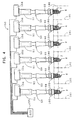
- FIG. 3 shows an ignition system employing the spark plugs 100.
- an ignition system 150 does not employ a distributor, but includes ignition coils 51 adapted to directly apply voltage to the corresponding spark plugs 100.
- Each of the ignition coils 51 includes a primary coil 52 adapted to receive electricity from a battery 156 and connected to an igniter 154.
- the ignition coil 51 further includes a secondary coil 53 connected to the corresponding spark plug 100.
- the igniter 154 includes contactless switches, such as transistors, corresponding to the ignition coils 51.
- each of the contactless switches comes into a broken or open state.
- a diode 5 la is provided between each ignition coil 51 and each spark plug 100 in order to prevent re-electrification of the spark plug 100, which would otherwise occur when the corresponding contactless switch returns to a conducting state from the open state.
- the spark plug 100 is mounted, by means of the mounting screw portion 7, on each of cylinders 181 such that the spark discharge gap g is located within a combustion chamber.
- Coil units 50 are attached to the spark plugs 100 in one-to-one correspondence and are connected to the electronic control unit 155.
- the coil unit 50 includes a casing 60 fitted to the rear end portion of the spark plug 100. The casing accommodates the ignition coil 51 and the igniter 154.
- the ignition coil 51 is electrically connected to the metallic terminal 13 of the spark plug 100 by means of an unillustrated terminal portion of the coil unit 50.
- the resistor 15 may be omitted, and the metallic terminal 13 and the center electrode 3 may be connected by means of, for example, a single conductive glass seal layer.
- the conductive glass seal layer 16 may be omitted.
- a resistor may be disposed, for example, between the ignition coil 51 and the terminal portion of the coil unit 50 so as to establish an electric resistance of not less than 10 k ⁇ (preferably not less than 15 k ⁇ ) but not greater than 25 k ⁇ between the ignition coil 51 and the center electrode 3 of the spark plug 100.
- Fine glass powder (average grain size 80 ⁇ m; 30 parts by weight), ZrO 2 powder (average grain size 3 ⁇ m; 60 parts by weight) serving as ceramic powder, Al powder (average grain size 20-50 ⁇ m; 1 part by weight) serving as metal powder, carbon black (2-9 parts by weight) serving as nonmetallic conductive substance powder, and dextrin (3 parts by weight) serving as an organic binder were mixed.
- the resulting mixture was wetmilled in a ball mill while water was used as solvent.
- the resulting mixture was dried, obtaining a preliminary material.
- Coarse glass powder (average grain size 250 ⁇ m) was mixed with the preliminary material in an amount of 400 parts by weight per 100 parts by weight of the preliminary material, obtaining a resistor composition in the form of powder.
- a material for the glass powder was borosilicate lithium glass, which was obtained by the steps of mixing 50 parts by weight SiO 2 , 29 parts by weight B 2 O 5 , 4 parts by weight Li 2 O, and 17 parts by weight BaO and melting the resulting mixture and whose softening temperature was 585°C.
- the resistors 15 were formed from the resistor composition powder by use of a hot press.
- the center electrode 3 was formed from an Ni alloy (INCONEL 600) and had an axial length of 20.7 mm and a cross-sectional diameter of 2.6 mm.
- the diameter of the through-hole 6 formed in the insulator 2 was 4.0 mm.
- Hot pressing was performed at a heating temperature of 900°C and an applied pressure of 100 kg/cm 2 .
- Conductive glass powder employed was a mixture of conductive powders of, for example, Cu, Fe, Sn, and TiO 2 , and borosilicate calcium glass powder (the conductive powders are contained in an amount of approximately 50% by weight).
- the length L2 of the resistor 15 was 7.0 mm to 15.0 mm.
- the electric resistance R k as measured between the center electrode 3 and the metallic terminal 13 was adjusted to 5 k ⁇ to 30 k ⁇ through adjustment of the length L2 and composition of the resistor 15.
- the spark portions 31 and 32 were fabricated in the following manner. Ir and Pt of predetermined amounts were mixed and melted, thereby obtaining an alloy which contains Pt in an amount of 5% by weight and Ir as the balance.
- the alloy was formed into disk chips having a diameter of 0.2 mm to 1.6 mm and a thickness of 0.6 mm.
- the spark portions 31 and 32 of the spark plug 100 shown in FIGS. 1 and 2 were formed (in other words, spark plug samples having spark portions of various sizes ranging from 0.2 mm to 1.6 mm were fabricated).
- the spark discharge gap g was initially set to various values of ⁇ ranging from 0.4 mm to 1.4 mm.
- the thus-obtained spark plug samples were mounted on a 6-cylinder gasoline engine (engine capacity 1998 cc).
- the engine was continuously operated for up to 800 hours at an engine speed of 5600 rpm (at a center electrode temperature of approximately 780°C) while throttles were completely opened. After engine operation was halted, an increase in the spark discharge gap g was measured.
- the test employed the ignition system shown in FIG. 3.
- the ignition system effected an electrical discharge under the following conditions: the polarity of the center electrode was negative; the peak value of the secondary current was 70 mA; and the discharge energy was 65 mJ. During discharge, current and voltage waveforms were recorded by use of an oscilloscope.
- DIS distributor ignition system
- FIG. 11 the electric resistance as measured between the ignition coil 251 and the far end of each high-tension cable C was set to 5 k ⁇ to 10 k ⁇ .
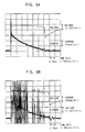
- FIG. 5 shows the results of a test for a gap-increasing behavior (i.e., electrode consumption).
- the test was conducted under the following conditions: the electric resistance Rk was 5 k ⁇ ; the end diameter 6 of the center electrode was 1.0 mm; and the initial spark discharge gap y was 0.5, 0.8, and 1.1 mm.
- spark plugs having an initial spark gap ⁇ of 0.8 or 1.1 mm cause a large amount of electrode consumption, so that the gap increases considerably. Since it was considered that the form of an electrical discharge was responsible for a difference in gap increase, waveforms of discharge were observed.
- FIG. 6A shows the waveform of an electrical discharge at a ⁇ value of 0.5 mm
- FIG. 6B shows the waveform of an electrical discharge at a ⁇ value of 0.8 mm.
- current shows a relatively stable behavior, implying that glow discharge is dominant.
- current frequently shows an abruptly increasing behavior, implying the occurrence of arc discharge.
- a strong current flows at the moment of transition from glow discharge to arc discharge.
- the frequency of transition from glow discharge to arc discharge within a single discharge cycle increases; hence, an instantaneous flow of a strong current occurs frequently, resulting in a significant consumption of the electrode.
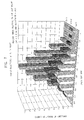
- FIG. 7 shows result of a test in which the frequency of transition from glow discharge to arc discharge was measured while the electronic resistance R k and the initial spark discharge gap ⁇ were changed.
- a first group of spark plugs in which the end diameter ⁇ of the center electrode was set to 1.0 mm and the electronic resistance R k was set to 5 k ⁇ were manufactured, while the initial spark discharge gap y was changed in the range of 0.4 - 1.4 mm.
- the spark plugs were mounted on the engine of a test car, and the test car underwent a test run. While a travelling pattern specified in JIS D1606 is taken as one cycle, there was counted the number of cycles until a rough idle occurred or until the insulation resistance of the spark plug sample decreased to 1 M ⁇ or less (the number of durability cycles). Resistance to contamination was evaluated in terms of the number of durability cycles. The test results are shown in FIG. 12. As seen from FIG. 12, when the value of ⁇ exceeds 1.2 mm, the number of durability cycles begins to decrease, indicating impairment in resistance to contamination.
- FIG. 8 shows results of a test performed for each of the DLI system of FIG. 3 and the DIS system of FIG. 11, in which the frequency of transition from glow discharge to arc discharge was measured while the electric resistance R k was changed. That is, for each of the DLI system of FIG. 3 and the DIS system of FIG. 11, spark plugs having initial spark discharge gap ⁇ of 0.8 mm were manufactured such that the spark plugs had respective R k values with in the range of 5 k ⁇ - 30 k ⁇ . The frequency of transition was measured for each of the thus-manufactured spark plugs. Table 2 shows measurements. Electric resistance (k ⁇ ) Frequency of transition (index) DIS DLI 5.00 63.5 100 7.50 45.8 70 10.00 30.6 50 12.50 40 15.00 35 20.00 32 22.50 30 25 28 27.5 26 30 24
- the frequency of transition from glow discharge to arc discharge decreases with the electric resistance R k .
- the frequency of transition is suppressed as low as that in the case of the DIS system.
- a decrease in the frequency of transition becomes gradual.
- FIG. 9 shows a consumed volume of a center electrode per spark as measured with respect to spark plugs having various values of end diameter ⁇ of the center electrode after a continuous test operation of 800 hours was completed.
- This test employed an initial spark discharge gap ⁇ of 1.1 mm and an electric resistance R k of 5 k ⁇ .
- an electrode of a smaller diameter is consumed more per spark. Conceivably, this is because an electrode of a smaller diameter increases in temperature more readily and is thus more susceptible to temperature increase effected by glow-to-arc transition.
- FIG. 10 shows the behavior of gap increase with operating hours (up to 800 hours) as measured with respect to an electric resistance R k of 5 k ⁇ , 10 k ⁇ , and 15 k ⁇ .
- This test employed an initial spark discharge gap ⁇ of 0.5 mm and an end diameter ⁇ of 1.0 mm of the center electrode. As seen from FIG. 10, electrode consumption can be suppressed more effectively by increasing the electric resistance R k to 10 k ⁇ , and this effect is enhanced by increasing the electric resistance R k to 15 k ⁇ .
- FIG. 13 is a graph showing the results of a test performed in order to evaluate the ignitabilty of spark plug samples each manufactured such a manner that the spark discharge gap ⁇ was set to 0.8 mm, the end diameter ⁇ of the center electrode was set to 0.8 mm, and the electric resistance R k was set to a value in the range of 10 k ⁇ to 30 k ⁇ (the values are shown in Table 3).
- the spark plug samples were mounted on a 6-cylinder gasoline engine of a DOHC lean-burn type (engine capacity 1998 cc). The engine was operated at a boost pressure of 350 mmHg and an engine speed of 2000 rpm (corresponding to a driving speed of 60 km/h), while the air-fuel ratio was changed.
Landscapes
- Chemical & Material Sciences (AREA)
- Engineering & Computer Science (AREA)
- Combustion & Propulsion (AREA)
- Spark Plugs (AREA)
Claims (11)
- Zündkerze, umfassend eine Mittelelektrode (3), einen die Mittelelektrode (3) umgebenden Isolator (2), eine den Isolator (2) umgebende Metallhülse (1), eine der Mittelelektrode (3) gegenüberliegende Masseelektrode (4), einen Zündabschnitt (31, 32), der aus einem Metall gebildet ist, welches nicht weniger als 60 Gew.-% Ir enthält, fest an zumindest einer Elektrode von der Mittelelektrode (3) und der Masseelektrode (4) angebracht ist, um eine Funkenentladungsstrecke (g) zu definieren, einen metallischen Anschluß (13), der fest in dem einen Endabschnitt eines axial in dem Isolator (2) ausgebildeten Durchgangslochs (6) angebracht ist, wobei die Mittelelektrode (3) fest in dem anderen Endabschnitt des Durchgangslochs (6) angebracht ist, und ein Widerstand in dem Durchgangsloch (6) zwischen dem metallischen Anschluß (13) und der Mittelelektrode (3) angeordnet ist, dadurch gekennzeichnet, daß der Widerstand (15) einen elektrischen Widerstandswert von nicht weniger als 10 kΩ, jedoch nicht mehr als 25 kΩ besitzt.
- Zündkerze nach Anspruch 1, dadurch gekennzeichnet, daß der elektrische Widerstandswert zwischen dem metallischen Anschluß (13) und der Mittelelektrode (3) nicht weniger als 15 kΩ beträgt.
- Zündkerze nach Anspruch 1 oder 2, dadurch gekennzeichnet, daß der Zündabschnitt (31, 32) an einem Endabschnitt der Mittelelektrode (3) ausgebildet ist, und der Durchmesser des Endabschnitts der Mittelelektrode (3) nicht größer als 1,1 mm ist.
- Zündkerze nach Anspruch 3, dadurch gekennzeichnet, daß der Durchmesser des Endabschnitts der Mittelelektrode (3) auf 0,3 mm bis 0,8 mm eingestellt ist.
- Zündkerze nach Anspruch 1, 2, 3 oder 4, dadurch gekennzeichnet, daß die Funkenentladungsstrecke (g) nicht größer als 1,2 mm ist.
- Zündkerze nach Anspruch 5, dadurch gekennzeichnet, daß die Funkenentladungsstrecke (g) nicht größer als 0,8 mm ist.
- Zündanlage zur Verwendung bei einem Verbrennungsmotor, umfassend:
eine Zündkerze (100), welche aufweist:wobei ein Widerstandsabschnitt zwischen der Zündspule (51) und der Mittelelektrode (3) angeordnet ist, um einen elektrischen Widerstandswert von nicht weniger als 10 kΩ und nicht mehr als 25 kΩ zwischen der Zündspule (51) und der Mittelelektrode (3) zu schaffen.eine Mittelelektrode (3), einen die Mittelelektrode (3) umgebenden Isolator (2), eine den Isolator (2) umgebende Metallhülse (1), eine der Mittelelektrode (3) gegenüberliegende Masseelektrode (4), einen Zündabschnitt (31, 32), der aus einem Metall gebildet ist, welcher nicht weniger als 60 Gew.-% Ir enthält, fest an zumindest einer Elektrode von der Mittelelektrode (3) und der Masseelektrode (4) angebracht ist, um eine Funkenentladungsstrecke zu definieren, einen metallischen Anschluß (13), der fest in dem einen Endabschnitt eines axial in dem Isolator (2) ausgebildeten Durchgangslochs (6) angebracht ist, wobei die Mittelelektrode (3) fest in dem anderen Endabschnitt des Durchgangslochs (6) angebracht ist, und ein Widerstand in dem Durchgangsloch (6) zwischen dem metallischen Anschluß (13) und der Mittelelektrode (3) angeordnet ist, dadurch gekennzeichnet, daß sie weiterhin aufweist:eine Spuleneinheit (50), mit einem an der Zündkerze (100) befestigten Gehäuse (60), wobei in dem Gehäuse eine Zündspule (51) aufgenommen ist, welche an dem metallischen Anschluß (13) der Zündkerze (100) angeschlossen ist, um eine Hochspannung an die Zündkerze (100) zum Bewirken einer elektrischen Entladung anzulegen, - Zündanlage nach Anspruch 7, dadurch gekennzeichnet, daß der Widerstandsabschnitt einen elektrischen Widerstand von nicht weniger als 15 kΩ zwischen der Zündspule und der Mittelelektrode (3) schafft.
- Zündkerze nach einem der Ansprüche 1 bis 6 oder Zündanlage nach Anspruch 7 oder 8, dadurch gekennzeichnet, daß der Zündabschnitt (31, 32) aus einem Metall gebildet ist, welches Ir als Hauptkomponente und außerdem Rh in einer Menge von 3 Gew.-% bis (ausschließlich) 50 Gew.-. % enthält.
- Zündkerze nach einem der Ansprüche 1 bis 6 oder Zündanlage nach Anspruch 7 oder 8, dadurch gekennzeichnet, daß der Zündabschnitt (31, 32) aus einem Metall gebildet ist, welches Ir als Hauptkomponente und Pt in einer Menge von 1 Gew.-% bis 20 Gew.-% enthält.
- Zündkerze nach einem der Ansprüche 1 bis 6 oder Zündanlage nach Anspruch 7 oder 8, dadurch gekennzeichnet, daß das Material des Zündabschnitts (31, 32) ein Oxid oder Komposit-Oxid eines metallischen Elements der Gruppe 3A oder der Gruppe 4A des Periodensystems in einer Menge von 0,1 Gew.-% bis 15 Gew.-% enthält.
Priority Applications (1)
| Application Number | Priority Date | Filing Date | Title |
|---|---|---|---|
| EP19990307498 EP0989646B1 (de) | 1998-09-22 | 1999-09-22 | Zündkerze und Zündanordnung zur Anwendung in einem Verbrennungsmotor |
Applications Claiming Priority (5)
| Application Number | Priority Date | Filing Date | Title |
|---|---|---|---|
| JP10268255A JP3075528B2 (ja) | 1998-09-22 | 1998-09-22 | スパークプラグ及び内燃機関用点火システム |
| JP26825598 | 1998-09-22 | ||
| EP99306552 | 1999-08-19 | ||
| EP99306552 | 1999-08-19 | ||
| EP19990307498 EP0989646B1 (de) | 1998-09-22 | 1999-09-22 | Zündkerze und Zündanordnung zur Anwendung in einem Verbrennungsmotor |
Publications (2)
| Publication Number | Publication Date |
|---|---|
| EP0989646A1 EP0989646A1 (de) | 2000-03-29 |
| EP0989646B1 true EP0989646B1 (de) | 2001-03-21 |
Family
ID=27240202
Family Applications (1)
| Application Number | Title | Priority Date | Filing Date |
|---|---|---|---|
| EP19990307498 Expired - Lifetime EP0989646B1 (de) | 1998-09-22 | 1999-09-22 | Zündkerze und Zündanordnung zur Anwendung in einem Verbrennungsmotor |
Country Status (1)
| Country | Link |
|---|---|
| EP (1) | EP0989646B1 (de) |
Families Citing this family (5)
| Publication number | Priority date | Publication date | Assignee | Title |
|---|---|---|---|---|
| JP4433634B2 (ja) * | 2000-06-29 | 2010-03-17 | 株式会社デンソー | コージェネレーション用スパークプラグ |
| EP1231687B1 (de) | 2001-02-13 | 2012-11-07 | Denso Corporation | Zündkerze und damit ausgestattete Zündvorrichtung |
| JP4747464B2 (ja) | 2001-08-27 | 2011-08-17 | 株式会社デンソー | スパークプラグおよびその製造方法 |
| JP4426494B2 (ja) | 2005-04-01 | 2010-03-03 | 株式会社日本自動車部品総合研究所 | 内燃機関用のスパークプラグ |
| KR101873662B1 (ko) * | 2013-12-20 | 2018-07-02 | 니뽄 도쿠슈 도교 가부시키가이샤 | 스파크 플러그 |
Family Cites Families (4)
| Publication number | Priority date | Publication date | Assignee | Title |
|---|---|---|---|---|
| JPS5232080B2 (de) * | 1972-11-08 | 1977-08-19 | ||
| JPH0782950B2 (ja) * | 1986-08-29 | 1995-09-06 | 日本電装株式会社 | 内燃機関用点火装置 |
| JPH0750192A (ja) * | 1993-08-04 | 1995-02-21 | Ngk Spark Plug Co Ltd | ガスエンジン用スパークプラグ |
| JPH09298083A (ja) * | 1996-04-30 | 1997-11-18 | Ngk Spark Plug Co Ltd | 内燃機関用スパークプラグ |
-
1999
- 1999-09-22 EP EP19990307498 patent/EP0989646B1/de not_active Expired - Lifetime
Also Published As
| Publication number | Publication date |
|---|---|
| EP0989646A1 (de) | 2000-03-29 |
Similar Documents
| Publication | Publication Date | Title |
|---|---|---|
| US6341501B2 (en) | Method of producing a spark plug | |
| EP0377938B1 (de) | Zündkerzenzusammenbau | |
| JP3140006B2 (ja) | スパークプラグ | |
| US4396855A (en) | Plasma jet ignition plug with cavity in insulator discharge end | |
| AU2007275029B2 (en) | High power discharge fuel ignitor | |
| US6724133B2 (en) | Spark plug with nickel alloy electrode base material | |
| US5998913A (en) | Spark plug with iridium-rhodium alloy discharge portion | |
| EP1837967A2 (de) | Plasmastrahlzündkerze und Zündungssystem | |
| US8188642B2 (en) | Spark plug for internal combustion engine | |
| US8536770B2 (en) | Plasma jet spark plug | |
| EP0805534B1 (de) | Zündkerze für Verbrennungsmotor | |
| EP0817342B1 (de) | Zündkerze | |
| US6326720B1 (en) | Spark plug and ignition system for use with internal combustion engine | |
| WO2022030072A1 (ja) | スパークプラグ | |
| EP0903824B1 (de) | Zündkerze | |
| US7122948B2 (en) | Spark plug having enhanced capability to ignite air-fuel mixture | |
| US6455988B1 (en) | Spark plug having a particular resistor | |
| EP0863591A1 (de) | Zündkerze mit Semi-Kriechstromentladung | |
| EP0989646B1 (de) | Zündkerze und Zündanordnung zur Anwendung in einem Verbrennungsmotor | |
| JP6312723B2 (ja) | スパークプラグ | |
| JP3734293B2 (ja) | 抵抗入りプラグ | |
| EP0376147B1 (de) | Zündkerzen für Verbrennungsmotoren | |
| JPH0612679B2 (ja) | スパ−クプラグ | |
| JP2000243536A (ja) | スパークプラグ及び内燃機関用点火システム | |
| DE69900064T2 (de) | Zündkerze und Zündanordnung zur Anwendung in einem Verbrennungsmotor |
Legal Events
| Date | Code | Title | Description |
|---|---|---|---|
| PUAI | Public reference made under article 153(3) epc to a published international application that has entered the european phase |
Free format text: ORIGINAL CODE: 0009012 |
|
| AK | Designated contracting states |
Kind code of ref document: A1 Designated state(s): DE FR GB IT |
|
| AX | Request for extension of the european patent |
Free format text: AL;LT;LV;MK;RO;SI |
|
| 17P | Request for examination filed |
Effective date: 20000202 |
|
| GRAG | Despatch of communication of intention to grant |
Free format text: ORIGINAL CODE: EPIDOS AGRA |
|
| 17Q | First examination report despatched |
Effective date: 20000626 |
|
| GRAG | Despatch of communication of intention to grant |
Free format text: ORIGINAL CODE: EPIDOS AGRA |
|
| GRAG | Despatch of communication of intention to grant |
Free format text: ORIGINAL CODE: EPIDOS AGRA |
|
| GRAH | Despatch of communication of intention to grant a patent |
Free format text: ORIGINAL CODE: EPIDOS IGRA |
|
| GRAH | Despatch of communication of intention to grant a patent |
Free format text: ORIGINAL CODE: EPIDOS IGRA |
|
| AKX | Designation fees paid |
Free format text: DE FR GB IT |
|
| GRAA | (expected) grant |
Free format text: ORIGINAL CODE: 0009210 |
|
| AK | Designated contracting states |
Kind code of ref document: B1 Designated state(s): DE FR GB IT |
|
| ITF | It: translation for a ep patent filed | ||
| REF | Corresponds to: |
Ref document number: 69900064 Country of ref document: DE Date of ref document: 20010426 |
|
| ET | Fr: translation filed | ||
| REG | Reference to a national code |
Ref country code: GB Ref legal event code: IF02 |
|
| PLBE | No opposition filed within time limit |
Free format text: ORIGINAL CODE: 0009261 |
|
| STAA | Information on the status of an ep patent application or granted ep patent |
Free format text: STATUS: NO OPPOSITION FILED WITHIN TIME LIMIT |
|
| 26N | No opposition filed | ||
| PGFP | Annual fee paid to national office [announced via postgrant information from national office to epo] |
Ref country code: GB Payment date: 20060920 Year of fee payment: 8 |
|
| PGFP | Annual fee paid to national office [announced via postgrant information from national office to epo] |
Ref country code: IT Payment date: 20060930 Year of fee payment: 8 |
|
| GBPC | Gb: european patent ceased through non-payment of renewal fee |
Effective date: 20070922 |
|
| PG25 | Lapsed in a contracting state [announced via postgrant information from national office to epo] |
Ref country code: GB Free format text: LAPSE BECAUSE OF NON-PAYMENT OF DUE FEES Effective date: 20070922 |
|
| PG25 | Lapsed in a contracting state [announced via postgrant information from national office to epo] |
Ref country code: IT Free format text: LAPSE BECAUSE OF NON-PAYMENT OF DUE FEES Effective date: 20070922 |
|
| PGFP | Annual fee paid to national office [announced via postgrant information from national office to epo] |
Ref country code: DE Payment date: 20150916 Year of fee payment: 17 |
|
| REG | Reference to a national code |
Ref country code: FR Ref legal event code: PLFP Year of fee payment: 18 |
|
| PGFP | Annual fee paid to national office [announced via postgrant information from national office to epo] |
Ref country code: FR Payment date: 20160816 Year of fee payment: 18 |
|
| REG | Reference to a national code |
Ref country code: DE Ref legal event code: R119 Ref document number: 69900064 Country of ref document: DE |
|
| PG25 | Lapsed in a contracting state [announced via postgrant information from national office to epo] |
Ref country code: DE Free format text: LAPSE BECAUSE OF NON-PAYMENT OF DUE FEES Effective date: 20170401 |
|
| REG | Reference to a national code |
Ref country code: FR Ref legal event code: ST Effective date: 20180531 |
|
| PG25 | Lapsed in a contracting state [announced via postgrant information from national office to epo] |
Ref country code: FR Free format text: LAPSE BECAUSE OF NON-PAYMENT OF DUE FEES Effective date: 20171002 |