EP0990616A1 - Personenbeförderungssystem - Google Patents
Personenbeförderungssystem Download PDFInfo
- Publication number
- EP0990616A1 EP0990616A1 EP98928526A EP98928526A EP0990616A1 EP 0990616 A1 EP0990616 A1 EP 0990616A1 EP 98928526 A EP98928526 A EP 98928526A EP 98928526 A EP98928526 A EP 98928526A EP 0990616 A1 EP0990616 A1 EP 0990616A1
- Authority
- EP
- European Patent Office
- Prior art keywords
- riser plate
- support frame
- pair
- step board
- sprockets
- Prior art date
- Legal status (The legal status is an assumption and is not a legal conclusion. Google has not performed a legal analysis and makes no representation as to the accuracy of the status listed.)
- Withdrawn
Links
Images






Classifications
-
- B—PERFORMING OPERATIONS; TRANSPORTING
- B66—HOISTING; LIFTING; HAULING
- B66B—ELEVATORS; ESCALATORS OR MOVING WALKWAYS
- B66B23/00—Component parts of escalators or moving walkways
- B66B23/14—Guiding means for carrying surfaces
-
- B—PERFORMING OPERATIONS; TRANSPORTING
- B66—HOISTING; LIFTING; HAULING
- B66B—ELEVATORS; ESCALATORS OR MOVING WALKWAYS
- B66B23/00—Component parts of escalators or moving walkways
- B66B23/14—Guiding means for carrying surfaces
- B66B23/147—End portions, i.e. means for changing the direction of the carrying surface
-
- B—PERFORMING OPERATIONS; TRANSPORTING
- B66—HOISTING; LIFTING; HAULING
- B66B—ELEVATORS; ESCALATORS OR MOVING WALKWAYS
- B66B23/00—Component parts of escalators or moving walkways
- B66B23/08—Carrying surfaces
- B66B23/12—Steps
Definitions
- the present invention relates to a passenger transportation conveyor apparatus such as an escalator, auto-lane or the like which can be installed easily, for example, on stairways in a railroad station, public facilities, along a slope or a flat plane.
- a passenger transportation conveyor apparatus such as an escalator, auto-lane or the like which can be installed easily, for example, on stairways in a railroad station, public facilities, along a slope or a flat plane.
- a prior art passenger transportation conveyor apparatus which is designed to reduce a space for installation of, for example, an escalator, and in particular, a height of its support frame have been disclosed, for example, in Japanese Patent Publication No. 48-19996 and Japanese Patent Laid-open No. 6-32577.
- the aforementioned prior art passenger transportation conveyor apparatus is comprised of substantially a large-sized guide wheel installed in a machine room on both sides of a longitudinal direction of its support frame, wherein a string of step-boards wound around the periphery of the large sized guide wheel are reversed of its direction of travel with the surfaces of their step boards being reversed or facing downward. Therefore, the height of the machine room or the support frame nevertheless has been reduced, thereby preventing for the space of installation of the passenger transportation conveyor from being reduced.
- An object of the invention is to provide for a novel passenger transportation conveyor apparatus that can accomplish reduction of a space for installation thereof by reducing a height of a machine room for its support frame.
- Another object of the invention is to provide for a passenger transportation conveyor that allows a plurality of step boards thereof to be transported smoothly along a forward direction and a return direction between floors/
- a passenger transportation conveyor comprising a plurality of step boards connected endlessly for circulating within its support frame construction, wherein said plurality of step boards are allowed to move circularly along the forward and return directions with their surfaces of step boards maintained upward.
- each step board moving along the forward direction (or return direction) enters a path of the return direction (or forward direction) with its upper surface of step board facing upward. Therefore, a height of its support frame structure is enough if there is a space to allow for each step board with its upper surface maintained upward to be transported between the forward and the return direction routes, because there is no need to provide for a large diameter guide wheel to allow for each step board to be reversed by 180 degrees. As a result, a height of the support frame structure at a portion thereof where a direction of movement of each step board is reversed can be substantially reduced thereby minimizing the space of installation thereof.
- a transfer mechanism for transferring each step board between the both directions while maintaining its upper surface facing upward is provided, thereby ensuring a smooth transfer thereof between the forward route and the return route.
- An escalator apparatus 1 has a support frame structure 41 including a pair of side frame structures 41A and a bottom frame 41B for connecting the pair of side frames 41A.
- This support frame structure 41 is installed on a staircase 6 provided from a lower floor 2 to an upper floor 3.
- both of the side frames 41A of this support frame 41 in a longitudinal direction thereof, a pair of upper sprockets 5 are mounted rotatably around its axis, and in a lower end portion thereof, a pair of lower sprockets are mounted rotatably.
- Side frame 41A has approximately a level surface on the upper and the lower end portions thereof and a tilt structure in its intermediate section with a tilt angle corresponding to staircase 6.
- a pair of drive chains are wound around the aforementioned upper sprocket 5 and the lower sprocket 4 symmetrically.
- This drive chain 7 is arranged to travel within or on a bottom frame 41B in its return route.
- a base end portion 8A of step board 8 is connected rotatably between the pair of symmetrical drive chains 7, and a horizontal transfer roller 8B is mounted rotatably via axis 8S at a play end portion of step board 8.
- This horizontal transfer roller 8B is guided by a guide rail 13 installed in both side frames 41A.
- This horizontal transfer roller 8B and guide rail 13 constitutes a guide means G.
- Guide rail 13 is provided in an intermediate tilt section along a forward direction of step board 8, and is positioned remote from drive chain 7 toward bottom frame 41B in a range from the lower portion of side frame 41A to the intermediate tilt section in the longitudinal direction of the side frame 41A, and is positioned once again near to drive chain 7 in the upper end portion in the longitudinal direction of side frame 41A. Further, this guide rail 13 is provided separate or disconnected from a return guide rail not shown.
- a pin protruding from base end portion 8A in lateral direction of step board 8 which is positioned toward the upper floor therein is connected rotatably to a connection portion of drive chain 7.
- a horizontal transfer roller 8B is rotatably mounted on axis 8S which protrudes in lateral direction from both sides of step board 8 positioned toward the lower floor 2.
- Guide rail 13 has a structure, which has a groove on its upper surface to guide movement of horizontal transfer roller 8.
- 7A and 7B depict a guide plate of drive chain 7, respectively.
- upper sprocket 5 When operating the above-mentioned escalator apparatus, upper sprocket 5 is driven by a drive source 9 such as a motor and a controller (not shown) at an appropriate speed. By selecting a forward or reverse operation of drive source 9, drive chain 7 can be moved freely in upper or lower directions.
- a drive source 9 such as a motor and a controller (not shown)
- step board 8 that is supported pivotally by drive chain 7 at its base end portion 8A ascends while maintaining its level state by moving drive chain 7 in a direction of arrow P.
- step board 8 that is supported pivotally by drive chain 7 at its base end portion 8A is allowed to descend while maintaining its level state by moving drive chain 7 in a direction of arrow Q.
- step board 8 In a case where step board 8 is moved circularly along its forward direction and return direction, a reversal action for reversing a direction of motion for step board 8 between the forward and the return routes, in particular, in the vicinity of lower sprocket 4 will be described with reference to Figs. 2A, 2B.
- an upper transfer guide rail 13A which is disconnected from the above-mentioned guide rail 13 is provided.
- This upper transfer guide rail 13A is pushed upward from the bottom immediately before horizontal transfer roller 8B of step board 8 passes to change its direction of movement from the return route to the forward route as indicated by dot and chain line in Figs. 2A.
- the upper transfer guide rail 13A is dropped to allow for the horizontal transfer roller 8B to ride over the upper transfer guide rail 13A in the reverse direction to get on guide rail 13 as indicated by dot and chain line in Figs. 2B.
- numeral "13 a” depicts a pivotal axis, that is, a rotary axis of the upper transfer guide rail 13A.
- the step board 8 is allowed to move along an external periphery of lower sprocket 4 with its upper surface constantly facing the upper direction.
- the upper floor 3 a pair of upper sprockets 5 are mounted on a different axis so that the step board 8 can pass a gap between the pair of upper sprockets 5.
- step board 8 is connected to drive chain 7 at its side end portion on the side toward the lower floor 2, it is necessary to arrange in a reversed mode such that the step board 8 is moved along the external periphery of the upper sprocket 5 in the upper floor 3 with its upper surface facing upward, and the step board 8 moves through a gap between the pair of lower sprockets 4 in the lower floor 2.
- step board 8 when the step board 8 is coupled with drive chain 7 at the forward end portion of step board 8 in its forward direction, it is arranged such that the step board 8 passes through between the pair of sprockets located in the forward direction of movement thereof.
- step board 8 when the step board 8 is coupled with drive chain 7 at the backward end portion of step board 8 in its forward direction, it is arranged such that the step board 8 passes through between the pair of sprockets located in the backward direction of movement thereof, thereby ensuring for the step board 8 to be able smoothly to travel circularly along the forward and the return routes.
- a portion without presence of guide rail 13 is provided in front of upper sprocket 5 in order to provide for a mechanism which allows horizontal transfer roller 8B to be dropped from the forward route to the return route without cause the step board 8 to be rotated by 180°.
- a transfer mechanism is constructed in a gap formed between the pair of upper sprockets 5, 5 and the pair of lower sprockets 4, 4 for allowing step board 8 to reverse freely its direction of movement while retaining its upper surface constantly facing the upper direction.
- Numeral 19 depicts a counter axis for distributing power from drive source 9 to the symmetrically disposed pair of upper sprockets 5.
- step board 8 because a direction of movement of step board 8 can be reversed without rotation thereof by 180°, the height of support frame structure 41 can be reduced. As a result, a space for installation thereof can be reduced, thereby allowing its installation, for example, on a staircase having a limited ceiling space without need of additional construction work.
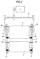
- a plurality of stair case anchor units 41P which are mountable on stair case 6 and comprise a pair of right and left side step anchor feet 41V, 41V and a connector 41H for connecting said pair of right and left side step anchor feet in a horizontal direction are provided integral with bottom frame 41B or side frame 41A of support frame structure 41 of the passenger transportation conveyor by fixing thereto.
- This step anchor unit 41 may be provided on every step or with an interval of every several steps.
- Materials for step anchor unit 41P can be selected appropriately as a pipe, plate, resin and the like.
- connecting member 41H is preferred to be provided integral with step anchor feet 41V, 41V (triangular flat plate in the embodiment), but it is not limited to such one having a flat bottom surface, and may be provided as a bar detachable with a pair of feet 41V, 41V. Further, connector member 41H alone may be provided as a foldable member.
- Step anchor unit 41P may be simply placed on the staircase 6 as required or removed therefrom freely, or may be permanently installed fixed to staircase 6 as a permanent escalator apparatus.
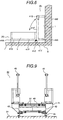
- a pivotal axis 41Z extending in a longitudinal direction of the stair case and a pivot mount table 41Y mounting pivotal axis 41Z thereon are provided on step 6 apart from step side wall 6W by a distance of a height of side frame 41A in order to provide for a mechanism to allow step anchor unit 41P is pivotally supported on the pivot mount table 41Y.
- step anchor unit 41P can be positioned alternately in position (B) in a storage state in an erected condition along step side wall 6W together with escalator apparatus 1 when there is no need to use the passenger transportation conveyor 1 thereby allowing use as a normal step 6, or in position (A) in a serviceable state as an escalator placed in a horizontal position along step 6.
- a retractable support table 41S is provided in step anchor unit 41P.
- This retractable support table 41S is locked in a position (A) protruded from the bottom surface of step anchor unit 41P when in use to support the bottom surface of step anchor unit 41P at a same level of height as that of pivot mount table 41Y, or locked in a retracted position (B) as retracted within step anchor unit 41P ensuring no protrusion from the bottom surface therefrom.
- an endless belt which is flexible
- wire or any other drive belts may be used in place of drive chain 7.
- An escalator apparatus is installed on staircase 6 extending from lower floor 2 to upper floor 3.
- a pair of drive chains 7 are provided as stretched between a pair of upper sprockets 5 on the upper floor and a pair of lower sprockets 4 on the lower floor.
- a plurality of step boards 8 are coupled to these drive chains 7.
- These drive chains 7 are driven by drive source 9 which is a motor in a direction of A thereby transporting passengers from lower floor 2 to upper floor 3.
- Each step board 8 is connected pivotally (free to change its angle) with drive chain 7 at its side end portion facing upper floor 3, and with a riser plate 10 at its another side end portion facing the lower floor.
- This riser plate 10 is placed in a drop position in a transport region which is a part of an upper stretch support frame region (forward side) for transporting passengers so as to close a gap between a next step board 8 to follow.
- a play end portion of riser plate 10 remote from the step board 8 is positioned juxtaposed to step board 8 in a retracted position such that riser plate 10 and step board 8 become approximately parallel with each other when moving.
- a base end portion of riser 10 is mounted pivotally (free to change its angle of rotation) on a pivotal axis which extends in a direction of width of step board 8, provided at the another end portion of the step board 8.
- a gear is fixed on this pivotal axis, and a guide cam of a folding fan shape is meshed with this gear.
- the guide cam has a circular arc periphery to mesh with the aforementioned gear, and by displacement of its angle, the riser 10 is subjected to displacement of angle and is folded into its retraction position.
- a suspending end portion of riser 10 coupled with step board 8 is guided by a guide rail 13 which is provided in an intermediate inclined section along the stair case so that riser 10 is position in its close position, and the step board 8 is moved maintaining its flat surface state.
- Cam guide roller 16 is provided toward upper floor 3, namely, in the vicinity of an end portion of the upper stretch support frame region to make contact with step board 8 moving horizontally on the side of upper floor 3, thereby causing for the guide cam to change its angle of contact by cam guide roller 16 along with movement of step board 8, thereby allowing for riser 10 to be positioned in its retraction position immediately before arriving at upper sprocket 5.
- riser 10 is transferred from the upper stretch support frame region to the lower stretch support frame region in a state as positioned in the retracted position.
- This folding mechanism for folding riser 10 in the retracted position is provided by each mechanism of riser 10 and cam guide roller 16 as described above.
- an upper transfer guide rail 17 is provided for transferring riser 10 in a state as positioned in the retracted position from the lower stretch support frame region to the upper stretch support frame region.
- Upper transfer guide rail 17 is pivotally supported at its upper end portion free to change its angle of rotation.
- the riser 10 is transferred from the lower stretch support frame region to the upper stretch support frame region in the state disposed in the retracted position, it is prevented for the riser 10 from interfering with a rotary axis 18 of the lower sprocket 4. In the vicinity of a starting point of the upper stretch support frame region, the riser 10 having passed bottom sprocket 4 returns to its original suspended position.
- a plurality of step boards 8 can be transferred while maintaining the surfaces of their step boards in the upper direction from the upper stretch support frame region to the lower stretch support frame region or vice versa.
- Escalator apparatus 30 is installed on staircase 33 extending from lower floor 31 in a lower direction to upper floor 32 in an upper direction.
- This escalator apparatus 30 has a support frame structure 41 installed extending from lower floor 31 to upper floor 32.
- a pair of upper sprockets 34 disposed apart from each other in an axial direction perpendicular to the plane of Fig. 8 are provided on support frame structure 41 on the side of upper floor 32 supported rotatably around an axial line extending in a direction of width thereof.
- a pair of lower sprockets 35 separated from each other in a width direction thereof are provided rotatably on the support frame structure 41 on the side of lower floor 32.
- a pair of drive chains 36 such as a pair of endless roller chains are wound around these upper and the lower sprockets 34 and 35 between the upper and the lower floors, and the plurality of step boards 37 are coupled between the pair of these drive chains 36.
- Each step board 37 is connected to drive chains 36 at its forward end portions, namely, at its side end portions facing the upper floor 32, mounted free to change its angle of rotation around a pivot axial line extending in parallel in the width direction described above.
- a base end portion (upper end portion) of riser 38 is connected free to change its angle of rotation to another end portions of each step board 37 opposite to the forward direction, i.e., portions facing the lower floor 31, around a pivot axial line in parallel with the direction of width.
- drive source 39 such as a motor is provided on the side of upper floor 32 of the support frame structure 41 .
- a drive force from drive source 39 is transmitted to an intermediate axis 47.
- Gears provided on both sides of this intermediate axis 47 which mesh with gears fixed on the pair of upper sprockets 34 transfer this drive force to the pair of upper sprockets 34.
- the drive force from the drive source 39 may be transmitted to each upper sprocket 34 also by using a chain as in the normal escalator apparatus.
- the drive source 39 allows for drive chain 36 to move each step board 37 in a direction from lower floor 31 to upper floor 32 in the upper stretch support frame region S1 of drive chain 36.
- a movement of step board 37 in the upper stretch support frame region S1 in an upward direction indicated by arrow A is defined to be upward direction A
- a that of step board 37 in the lower stretch support frame region S2 in a downward direction indicated by arrow B is defined to be downward direction B.
- Each upper sprocket 34 has a structure to allow for a drive force to be transmitted via intermediate axis 47, and has no axis of rotation extending between the pair of upper sprockets 34, thereby allowing for the step board 37 and the riser 38 to pass through a gap between the pair of the upper sprockets 34.
- the pair of the lower sprockets 35 have a common axis of rotation 40, therefore, riser 38 is transferred in the upper direction as disposed in its retracted position in order to avoid the aforementioned axis of rotation 40 as will be described later.
- a lower boarding floor 44 for passengers to step on in the forward direction On the side of lower floor 31 on support frame structure 41, a lower boarding floor 44 for passengers to step on in the forward direction is provided.
- an upper boarding floor 43 On the side of upper floor 31 on support frame structure 41, an upper boarding floor 43 is provided likewise.
- This region in the upper stretch support frame regions S1 for drive chain 36 between the lower boarding floor 44 and the upper boarding floor 43 where each step board 37 is exposed externally is defined to be a transport region S5.
- Each step board 37 is ensured to maintain its step surface 48 for boarding a passenger at level in this transport region S5, and each riser 38 associated with each step board is ensured to be positioned at its close position suspending in the bottom direction thereby closing a vertical gap formed between a preceding step board and a subsequent step board.
- a region of drive chain 36 in the vicinity of upper sprocket 34 where the chain is wound around the sprocket 34 is defined to be a lower transfer region S3.
- each step board 37 is moved from upper stretch support frame region S1 to lower stretch support frame region S2 while maintaining its step surface 48 faced in the upper direction.
- a portion thereof in the vicinity of lower sprocket 35 where the chain is wound around the sprocket 35 is defined to be an upper transfer region S4.
- each step board 37 is allowed to move from the lower stretch support frame region S2 to the upper stretch support frame region S1 with its step surface 48 facing in the upper direction.
- a pair of railings are erected on both sides in a lateral direction of support frame structure 41, and a handrail 45 is guided endlessly in a periphery of each of the pair of railings.
- This hand rail 45 which is driven circularly by a drive force from drive source 39 moves at a same speed as drive chain 36. Therefore, passengers boarding on the lower boarding floor 44 from the lower floor 31 by gripping hand rail 45 and onto the step surface 48 of step board 37 will be transported up to upper floor 32.
- the support frame 41 is fixed to lower floor 31, upper floor 32 and staircase 33 using a simple fixture means 46.
- This simple fixture means 46 having a concrete bolt and the like can be fixed removably.
- a hole bore may be provided in the lower floor 31, upper floor 32 and stair case 33 to receive each bolt of the simple fixture means 46 such that escalator apparatus of the invention can be installed easily by insertion of the bolt of simple fixture means 46 into the hole bore of the floors.
- the support frame structure 41 is divided into a plurality of sections, and a maximum length of the support frame is selected preferably less than 5 m. Therefore, transportation, assembly and removal of the escalator apparatus of the invention will become substantially easier.
- Fig. 10 is a cross-sectional view enlarged in part of Fig. 9 indicating a lateral cross-section in detail in the vicinity of step board 37.
- Fig. 11 is a side view indicating a state of riser 38 which is positioned in its closed position.
- Fig. 12 is a side view indicating another state of riser 38, which is positioned in its retracted position.
- Riser 37 and step board 38 are comprised of a plurality of comb plates, respectively.
- respective comb plates of each riser 38 and each step board 37 associated therewith are meshed in.
- step board 37 facing toward upper floor 32, there is provided a chain support axis 58 extending in an axial direction.
- this chain support axis 58 On both sides of this chain support axis 58, there are provided the guide roller 59 mounted free to rotate around the axial line of the chain support axis 58, and on both end portions of this chain support axis 58, there are connected drive chain 36 free to change its angle around the axial line of chain support axis 58.
- a step board upper guide rail 60 is provided along an intermediate inclined section of upper stretch support frame region S1 in a side wall 42 of support frame 41, and a step board lower guide rail 69 is provided along an inclined section in lower stretch support frame region S2 so that when step board 37 moves along the upper stretch support frame region S1, the guide roller 59 is guided along the step board upper guide rail 60, and when the step board 37 moves along the lower stretch support frame region S2, the guide roller 59 thereof is guided along the step board lower guide rail 69.
- upper chain guide rail 70 is provided along the upper stretch support frame region S1, and drive chain 36 on the upper stretch support frame region S1 is guided along this upper chain guide rail 70.
- a lower chain guide rail 71 is provided along lower stretch support frame region S2, and drive chain 36 is guided along this lower chain guide rail 71 in the lower stretch support frame region S2.
- angle displacement axis 64 extending in a lateral direction thereof free to change its angle of rotation, and to this angle displacement axis 64, a base end portion of riser 38 is fixed.
- a pair of guide rollers 55 At a play end portion of riser 38, there are provided a pair of guide rollers 55 at both ends of an axial line extending in a direction of width. Further, a pair of small rollers 61 having a smaller diameter than that of guide roller 55 are provided in juxtaposition with the guide roller 55 at a position slightly inward than the guide roller 55 in the width direction.
- step board 37 anchor end portion 63 pending downward is provided.
- riser 38 When riser 38 is positioned at its closure position, upper end portion 62 of riser 38 is supported by the aforementioned anchor end portion 63 by making contact therewith.
- Riser 38 is allowed to hang down and is positioned at its closure position in its natural state.
- Gear 65 is fixed at both ends of angle displacement axis 64 provided at the base end portion of riser 38.
- This gear 65 meshes with racks formed on a circular arc periphery of a guide cam 66 having a folding fan shape, which is positioned in juxtaposition with gear 65.
- Guide cam 66 is provided with a lever 49 fixed thereto, which lever 49 extends toward the another end portion of step board 37 and is inclined downwardly when riser 38 drops down toward its closure position.
- a guide roller 68 is provided on the side of upper floor 32 of support frame structure 41, which makes contact with the lever 49 of the guide cam 66.
- the aforementioned guide roller 68 makes contact with lever 49 of guide cam 66, and when step board 37 further advances in the right-hand direction, guide cam 66 rotates clockwise causing angle displacement as indicated in Fig. 12.
- gear 65 meshed with this guide cam 66 and the riser 38 fixed on this gear 65 are rotated anti-clockwise causing angle displacement until riser 38 becomes approximately parallel with step board 37 so as to be positioned at its retracted position. In this manner of operation, riser 38 is ensured to be positioned in its retracted position immediately before it reaches the lower transfer region S3.
- riser upper guide rail 56 under the step board upper guide rail 60 separated in a vertical direction from each other.
- Riser lower guide rail 57 is provided likewise under the step board lower guide rail 69 but in a close proximity to the step board lower guide rail 69.
- riser 38 is in the state of closure, and in the lower stretch support frame region S2, riser 38 is in the state of retraction, therefore, it becomes possible to reduce a space between the upper stretch support frame region S1 and the lower stretch support frame region S2, thereby providing for a compact-sized escalator apparatus 30 having a lower height.
- riser 38 travels in the state of closure as disposed in its closure position in the transport region S5
- small roller 61 of riser 38 makes contact with small roller guide rail 50 which is provided parallel to riser upper guide rail 56 from the bottom to the upper direction.
- riser 38 is prevented from making angle displacement to move toward the retraction side while traveling in the transport region S5 thereby ensuring for step board 37 to maintain its step surface 48 stably at level.
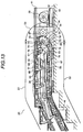
- Fig. 13 is a schematic side view of escalator apparatus 30 of the invention removed of its side wall 42 and in the vicinity of upper floor 32.
- a pair of riser rotation guide means 75 separated from each other in a width direction are provided in the vicinity of upper sprocket 34, rotatably around a rotor axis 76 having a rotation axial line L1 which is parallel to the axial line of upper sprocket 34 and is positioned internally than drive chain 36.
- This riser rotation guide means 75 is placed in a position where the riser upper guide rail 56, step board upper guide rail 60 and riser lower guide rail 57 are discontinued, and which constitutes a transfer mechanism for transferring step board 37 therebetween.
- Riser rotation guide means 75 is also provided with sprocket 51 coaxially.
- a chain 52 is stretch-mounted between this sprocket 51 and a sprocket 53 which is coaxially provided on upper sprocket 34, thereby rotating riser rotation guide means 75 at a same speed and in a same direction of rotation as upper sprocket 34.
- Riser rotation guide means 75 has a pair of receptor members 77, 78 formed symmetrically with respect to rotation axial line L1.
- step board 37 When step board 37 is transferred along the lower transfer region S3 from the upper stretch support frame region S1 to the lower stretch support frame region S2, the aforementioned receptor members 77, 78 are arranged to support the guide roller 55 provided at the play end portion of riser 38 to enable for the step board having its associated riser retracted in the retraction position to be guided from the upper stretch support frame region S1 to the lower stretch support frame region S2.
- Fig. 14 is a schematic side view enlarged of a portion in the vicinity of riser rotation guide means 75 immediately before the step board 37 reaches the lower stretch support frame region S3.
- Riser rotation guide plate 75 has a pair of receptor members 77, 78, each projecting externally approximately in radius directions, and each of these receptor members has a support surface 79.
- This support surface 79 is inclined at angle ⁇ 1 from a virtual plane 73 drawn by connecting between rotation axial line L1, respective edge portions 82 of respective receptor members 77, 78, in an opposite direction from a rotational direction C of riser rotation guide means 75 (in clockwise direction in Fig. 14).
- angle ⁇ 1 is selected from a range of 0° ⁇ 1 ⁇ 30°.
- a locus of contact between guide roller 55 of riser plate 38 and support surface 79 when riser plate 38 is guided from the upper stretch support frame region S1 to the lower stretch support frame region S2 is represented by a circle as indicated by a virtual circle 83. Its diameter D1 is approximately the same as diameter D2 of upper sprocket 34, therefore, riser plate 38 is ensured to be transported from the upper stretch support frame region S1 to the lower stretch support frame region S2 in the state retained in the retracted position thereof.
- a front end portion 57a toward the upper floor 32 of a riser lower guide rail 57 for guiding guide roller 55 of riser 38 in the lower stretch support frame region S2 is formed extending upward to make an angle ⁇ 2 coaxially around the center of rotation axial line L1 of riser rotation guide means 75.
- This angle ⁇ 2 is selected preferably from a range of 30° ⁇ 2 ⁇ 90°, and more preferably, at 52°.
- angle ⁇ 2 is smaller than 30°, there arises such a problem that when step board 37 descends to the lower stretch support frame region S2, guide roller 55 of riser 38 may collide with riser lower guide rail 57 severely, thereby producing a noise.
- angle ⁇ 2 is larger than 90°, there arises such a problem that the front end portion 57a of riser lower guide rail 57 becomes too long thereby failing to ensure a sufficient strength.
- the riser plate guide means of the invention is comprised of the front end portion 57a of riser plate lower guide rail 57 and the riser plate rotation guide means 75 as described above.
- a distance a1 between rotation axial line L1 of riser plate rotation guide means 75 and rotation axial line L2 of upper sprocket 34 is selected to be equal to a distance a2 between the axial line of chain support axis 58 of step board 37 and the rotation axial line of guide roller 55 of riser 38 which is folded in the retracted position.
- riser plate rotation guide means 75 is also rotated by the same angle, and step board 37 is maintained approximately at level and riser plate 38 is retained in the retracted position.
- riser plate 38 tends to rotate around angle displacement axis 64 to change its angle toward the position of closure, its angle displacement is prevented by the support surface 79 of receptor member 77.
- riser plate guide means 75 also rotates by the same angle responsive thereto, thereby ensuring for step board 37 to be transferred approximately in a state of level while retaining its associated riser plate 38 in the retracted position.
- guide roller 55 is guided along riser plate lower guide rail 57 until a support surface 79 of the other receiver member 78 which is formed symmetrically with respect to rotation axial line L1 is to face a guide roller 55 of another step board 37 subsequent thereto from beneath thereof.
- receiver member 78 of the other is arranged to receive guide roller 55 of the subsequent step board 37 to follow thereby representing the same state of Fig. 14 described above.
- riser plate rotation guide means 75 is rotated at the same speed as upper sprocket 34 thereby ensuring for each riser plate 38 of subsequent step boards 37 to be guided sequentially to the lower stretch support frame region S2.
- riser plate lower guide rail 57 is formed in a circular arc coaxially around rotation axial line L1 of riser plate rotation guide means 75, the guide roller 55 can be smoothly guided along the circular arc around the rotation axial line L1 by the riser plate rotation guide means 75.
- riser plate 38 By smooth guidance of riser plate 38 as described above, noise generation can be prevented, and step boards 37 can be moved smoothly in a circulation route.
- a side view of escalator apparatus 30 of the invention in the vicinity of lower floor 31 is indicated with side wall 42 removed.
- Riser plate lower guide rail 57 is provided with an inclined end portion 90 in a lower traveling direction of B, which rises upward in the down stream of B. Beneath this inclined end portion 90 of riser plate lower guide rail 57, there is provided a riser plate guide roller 94.
- a pair of riser plate guide rollers 94 are provided apart from each other in a lateral direction between the inclined end portion 90 of riser plate lower guide rails 57 which are provided separately from each other in a direction of width.
- the pair of riser plate guide rollers 94 are mounted free to rotate around a rotation axial line thereof extending in a lateral direction, and are disposed such that its periphery faces riser plate 38 from beneath which is guided along the inclined end portion 90.
- riser plate guide member 95 These inclined end portion 90 of riser plate lower guide rails 57 and riser plate guide rollers 94 constitute riser plate guide member 95.
- first riser plate guide rail 91 In the upper direction of inclined end portion 90 of riser plate lower guide rails 57, there is provided a first riser plate guide rail 91 whose upward inclination becomes greater in the downstream in the upper travel direction of A.
- the first riser plate guide rail 91 is provided between the inclined end portion 90 of riser plate lower guide rails 59 and a horizontal guide rail 92 for guiding riser plate 38 which is retained in the retracted position in a horizontal direction in the upper stretch support frame region S1.
- the first riser plate guide rail 91 is comprised of: a support piece 97 which is disposed external from drive chain 36; a connection guide rail 98 which is disposed internally than drive chain 36, and is connected to the horizontal guide rail 92; and an open/close guide member 96 which is supported, free to change its angle, by the connection guide rail 98 and the support piece 97, and is disposed between the support piece 97 and the connection guide rail 98.
- Close/open guide member 96 is provided across a path of chain, i.e., chain support axis 58 provided on the one end of step board 37. Therefore, in order to avoid interference thereof with the path of the chain support axis 58 when step board 38 moves from lower stretch support frame region S2 to upper stretch support frame region S1, a base end of the close/open guide member 96 is mounted on an upper end of support piece 97 free to change its angle around an angular displacement axial line extending in a width direction, and a play end portion thereof is anchored on a backward end of connection guide rail 98 (in the left-hand direction in Fig.
- open/close guide member 96 is pushed upward in its open position by the chain support axis to allow for the same to pass between the open/close guide member 96 and connection guide rail 98 when chain support axis 58 of step board 37 traverses, and open/close member 96 is closed after chain support axis 58 has passed therethrough.
- the open/close guide member 96 is made of a synthetic resin such as acrylic resin, occurrence of noise can be prevented every time it collides with metallic connection guide rail 98.
- Each part of surfaces facing upward of the support piece 97, open/close guide member 96 and connection guide rail 98 of the first guide rail 91 provide a smooth continuous surface in combination for guiding the guide roller 55 of riser plate 38 up to horizontal guide rail 92.
- a lower end portion 97a (to the left-hand side in Fig. 23) of the support piece 97 of the first riser guide rail 91 is provided in the upper and in the direction of A than riser plate guide roller 94, and a distance b1 from the inclined end portion 90 of riser plate lower guide rail 57 is selected at a value slightly larger than an external diameter D3 of guide roller 55.
- connection guide rail 98 of the first riser plate guide rail 91 provides for a smooth connection to horizontal guide rail 92 which guides step board 37 horizontally while retaining its riser plate 38 in the retracted position for step board 37 when the same is horizontally guided along upper stretch support frame region S1 on the lower floor 31.
- This front end 98a of connection guide rail 98 is disposed in the upper and in the downstream of A (to the right-hand side in Fig. 23) than the rotation axis 40 of the lower sprocket 35.
- the first riser plate guide rail 91 and the riser plate guide member 95 which are disposed in the position where the riser plate lower guide rail 57 and the step board upper guide rail 60 are discontinuous constitute in combination the transfer mechanism for guiding step board 37 therethrough and transferring the same therebetween.
- a front end 92a of horizontal guide rail 92 (the right hand side thereof in Fig. 23) is connected smoothly to a second riser plate guide rail 93.
- the second riser plate guide rail 93 is formed to have a slope descending downward in the direction of A.
- step board 37 moves in the direction of A
- the guide roller 55 provided at the play end portion of riser plate 38 is guided by this descending slope such that rise plate 38 is disposed smoothly at its closure position immediately before it reaches transport region S5.
- a small roller guide rail 99 (see Fig.
- step board 37 which is traveling horizontally in the direction of B in lower stretch support frame region S2 on the lower floor 31 arrives in the vicinity of upper transfer region S4, and when step board 37 ascends along the lower sprocket 35, the guide roller 55 on riser plate 38 is guided onto the inclined end portion 90 of riser plate lower guide rail 57 so as to displace riser plate 38 also in the upper direction, thereby allowing for the riser plate 38 to be guided into the upper direction in a state retained in the retracted position.
- step board 37 when the lower sprocket 35 is further rotated until one end of step board 37 reaches a center portion of upper transfer region S4, a direction of travelling of step board 37 is reversed from the lower travel direction of B to the upper travel direction of A, and as indicated in Fig. 24, guide roller 55 rides onto support piece 97 of the first riser plate guide rail 91. As step board 37 advances in the upper travel direction of A, the guide roller 55 of riser plate 38 is guided on a surface of close/open guide member 96 and connection guide rail 98.
- angle ⁇ 3 obtained between a line connecting a rotating axial line of guide roller 55 with an axial line of angular displacement axis 64 of step board 37 and a surface of support piece 97 is preferably selected in a range that 0° ⁇ 3 ⁇ 90°.
- angle ⁇ 4 formed between the line connecting the angular displacement axis of riser plate 38 with the rotation axial line of guide roller 55 and the surface of step board 37 is preferably selected in a range of 0° ⁇ 4 ⁇ 90°.
- the guide roller 55 is guided along the first riser plate guide rail 91 in the upper direction of rotational axis 40 of the lower sprocket 35 and up to the downstream of the upper travel direction A with the riser plate 38 being retained in the retracted position, it can be avoided for the riser plate 38 to interfere with the rotational axis 40 of the lower sprocket 35, thereby ensuring for step board 37 to move smoothly.
- step board 37 further advances in the upper travel direction A in the upper stretch support frame region S1
- the guide roller 55 is guided along horizontal guide rail 92, and when guide roller 55 arrives at the second riser plate guide rail 93, guide roller 55 makes contact with the second riser plate guide rail 93 in the bottom direction, then smaller roller 61 makes contact with small roller guide rail 99, and with advancement of step board 37 in the upper travel direction A, the guide roller 55 is guided such that its riser plate 38 is smoothly placed in the retracted position thereof.
- riser plate 38 is rapidly released from the retracted position to the closure position thereby allowing for the upper end portion 62 of the riser plate to collide with anchor end portion 63 of step board 38, and thereby preventing for each step board 37 to travel smoothly due to impact of this collision.
- riser plate 38 is ensured to be positioned in the closure position immediately before entering the transport region S5 by action of the second riser plate guide rail 93.
- each step board 37 is traveling in the upper direction in the upper stretch support frame region S1 from the lower floor 31 to the upper floor 32, however, it is not limited thereto, and the same advantages and features according to the invention can be accomplished when applied to the downward destined escalator as well.
- Fig. 25 is a side view of an escalator apparatus 100 according to a fourth embodiment of the invention.
- the same components and parts as in Figs 1-24 are labeled with the same reference numbers.
- a stair case 33 on which escalator apparatus 100 is installed has a platform 101 which is level disposed between lower floor 31 and upper floor 32.
- a drive chain 36 is stretched along the staircase 33 having such platform 101, and support frame 41 is also installed along this staircase 33.
- escalator apparatus 100 has a level portion in the platform 33.
- step board 37 can be arranged to travel circularly between the upper and the lower floors along drive chain 36 for transporting passengers from the lower floor up to the upper floor.
- Fig. 25 is a side view of an escalator apparatus 105 according to a fifth embodiment of the invention, in part, in the vicinity of upper floor 32.
- the same components and parts as in Figs. 8-24 are labeled with the same reference numbers.
- a riser plate guide means 106 is provided in the vicinity of upper sprocket 34 on the upper floor 32 for guiding a guide roller 55 provided on a play end portion of riser plate 38 associated with a step board 37 when step board 37 is moving from upper stretch support frame region S1 to lower stretch support frame region S2 in lower transfer region S3 while retaining riser plate 38 positioned in its retracted position.
- Fig. 27 is an enlarged side view in part of the escalator in the vicinity of riser plate guide means 106.
- a path of motion of chain support axis 58 of step board 37 in Fig. 27 is indicated sequentially in periods of time elapsed by virtual lines 58a-58k of the chain support axis 58, and a path of motion of guide roller 55 corresponding thereto is indicated by sequentially by virtual lines 55a-55k likewise.
- a riser plate retraction guide member 109 is provided on the side of a front end portion of riser plate upper guide rail 56 in the upper stretch support frame region S1 , which is inclined in the upper direction in the downstream of the upper travel direction A for guiding guide roller 55 of step board 38 as retained in the retracted position.
- the riser plate 38 When traveling in the upper travel direction A in the upper stretch support frame region S1, the riser plate 38 is caused to be positioned in its retracted position immediately before arriving at lower transfer region S3 by guide roller 68.
- retraction guide member 109 auxiliarily guides the guide roller 55, and prevents riser plate 38 from displacing its angle toward the closure position when guide cam 66 of step board 37 leaves from guide roller 68.
- Riser plate guide means 106 is comprised of upper guide member 107 and lower guide member 108, wherein the upper guide member 107 is disposed internal of a path of transfer of guide roller 55 of riser 38, and has an upper guide surface 107a which makes contact with the guide roller 55 and support the same from the bottom such that the riser plate is retained in the retraction position and the step board 37 is guided in a state approximately in level when chain support axis 58 provided at one end of riser 37 is moved from the upper end to the center portion in lower transfer region S3.
- Lower guide member 108 is disposed externally from the path of transfer of guide roller 55 of the riser plate.
- chain support axis 58 provided on one portion of step board 37 is moved from the center portion in the lower transfer region to lower stretch support frame region S2
- the lower guide member 108 makes contact with the guide roller 55 of riser 38 from the bottom such that riser plate 38 is ensured to be positioned in the retracted position and that step board 37 is guided in a state approximately in level.
- This lower guide member 108 is comprised of: a circular arc guide rail 113; and a lower end guide member 110 which is inclined from a lower end of guide rail 113 toward riser plate lower guide rail 57 and is mounted free to rotate around an angular displacement axial line extending in a width direction in a back side of the guide rail 113 (on the right-hand side in Fig. 27), wherein an internal periphery 113a of guide rail 113 facing upward and a surface 110a of lower end guide member 110 facing upward constitute a lower guide surface of the lower guide member 108.
- upper displacement prevention member 112 is provided opposite to the lower guide member 108.
- a front end portion 111 (on the right-hand side in Fig. 27) of riser plate lower guide rail 57 for guiding guide roller 55 of riser 38 in the lower stretch support frame region S2 is formed to have an upper inclination toward the lower end guide member 110.
- step board 37 is guided approximately in a state of level with its associated riser plate 38 being retaining in the retracted position.
- the lower end guide member 110 is provided capable of angular displacement as described previously, the same is allowed to adjust its angle such that the guide roller 55 is smoothly guided from the bottom end of guide rail 113 toward the front end portion 111 of riser plate lower guide rail 57.
- the riser plate guide means 106 As described hereinabove, because the riser plate is ensured to be guided smoothly as retained in the retracted position by the riser plate guide means 106 during its transition from the upper stretch support frame region S1 to the lower stretch support frame region S2, the problem associated with the prior art that the prior art guide roller suspending from a prior art riser plate collides severely with a lower stretch support frame region S2 when descending so as to generate a noise and/or prevent a smooth travel of each step board can be solved according to the invention.
- Respective embodiments of the invention described herein above have been made by way of example of respective escalator apparatuses that can be installed on existing staircases, however, it is not limited thereto, and the present invention can be applied to a new escalator apparatus that is to be installed, for example, along any slope in a house, building, or in the field.
- Still another embodiment of the invention which is not limited to the escalator system can be contemplated as a sixth embodiment of the invention such as, for example, an auto lane 200 indicated in Fig. 28.
- This auto lane 200 is installed on a level plane floor, and has such a structure that a part of its support frame 201 is buried under the floor, a pair of drive side sprockets 203 supported by each independent axis to be driven by a transport drive source 202 are provided rotatably on both sides of one end portion in the longitudinal direction of support frame 201, while on the both sides of the other one end portion thereof, a pair of follower sprockets 204 are supported rotatably around a common axis.
- a pair of endless drive chains 205 are wound around these pairs of sprockets 203 and 204, and stretched therebetween. Then, a plurality of step boards 206 are coupled between the pair of endless drive chains.
- An upper guide rail 207 is installed extending between these two pairs of sprockets 203 and 204 on the side of forward path so as to guide step boards 206 in a state of level. Further on the side of return path of step boards 206, a lower guide rail 208 is installed between these two pairs of sprockets 203 and 204 such that step boards 206 do not interfere with the bottom portion of support frame 201.
- the escalator apparatus has been provided featuring in that the height dimension of the machine room for accommodating the support frame structure 201 can be reduced so as to be able to minimize the space for installation thereof, and that the reversal of directions of movement of each step board can be performed smoothly without interference.
Landscapes
- Escalators And Moving Walkways (AREA)
Applications Claiming Priority (5)
| Application Number | Priority Date | Filing Date | Title |
|---|---|---|---|
| JP17763797 | 1997-06-17 | ||
| JP17763797 | 1997-06-17 | ||
| JP33322797 | 1997-12-03 | ||
| JP33322797 | 1997-12-03 | ||
| PCT/JP1998/002673 WO1998057880A1 (fr) | 1997-06-17 | 1998-06-17 | Systeme de transport de pietons |
Publications (2)
| Publication Number | Publication Date |
|---|---|
| EP0990616A1 true EP0990616A1 (de) | 2000-04-05 |
| EP0990616A4 EP0990616A4 (de) | 2001-03-14 |
Family
ID=26498121
Family Applications (1)
| Application Number | Title | Priority Date | Filing Date |
|---|---|---|---|
| EP98928526A Withdrawn EP0990616A4 (de) | 1997-06-17 | 1998-06-17 | Personenbeförderungssystem |
Country Status (7)
| Country | Link |
|---|---|
| US (1) | US6234295B1 (de) |
| EP (1) | EP0990616A4 (de) |
| KR (1) | KR100487037B1 (de) |
| CN (1) | CN1139533C (de) |
| AU (1) | AU737547B2 (de) |
| RU (1) | RU2191153C2 (de) |
| WO (1) | WO1998057880A1 (de) |
Cited By (5)
| Publication number | Priority date | Publication date | Assignee | Title |
|---|---|---|---|---|
| WO2003051756A1 (de) * | 2001-12-15 | 2003-06-26 | Kone Corporation | Antrieb für einen rollsteig mit geringer paletten-umlaufbauhöhe |
| WO2007065397A1 (de) * | 2005-12-06 | 2007-06-14 | Kone Corporation | Umlenkbereich für paternosterartige rolltreppen oder rollsteige |
| WO2011078638A1 (es) * | 2009-12-21 | 2011-06-30 | Vasquez Lombera Juan | Escalera eléctrica |
| CN103030057A (zh) * | 2011-09-30 | 2013-04-10 | 康力电梯股份有限公司 | 一种自动扶梯卸载导轨结构 |
| WO2014070187A1 (en) | 2012-11-01 | 2014-05-08 | Otis Elevator Company | Turnaround mechanism for passenger conveyors |
Families Citing this family (20)
| Publication number | Priority date | Publication date | Assignee | Title |
|---|---|---|---|---|
| AU744620B2 (en) * | 1998-04-30 | 2002-02-28 | Liset Products Pty Ltd | Method and apparatus for building a cotton module |
| JP2001192194A (ja) * | 1999-10-25 | 2001-07-17 | Toshiba Elevator Co Ltd | 乗客コンベヤ装置 |
| DE50114458D1 (de) * | 2000-03-27 | 2008-12-18 | Inventio Ag | Führungseinrichtung für Fahrtreppenstufe oder Fahrsteigpalette |
| US20040134749A1 (en) * | 2000-12-21 | 2004-07-15 | Matthias Lunacek | Deflector for an escalator or moving sidewalk |
| WO2003099686A1 (en) * | 2002-05-20 | 2003-12-04 | Otis Elevator Company | Escalator drive mechanism with failure detection and backup |
| FI116053B (fi) * | 2003-11-03 | 2005-09-15 | Kone Corp | Menetelmä ja laitteisto paletin liikesuunnan vaihtamiseksi liukukäytävän tai vastaavan päässä |
| FI20040303L (fi) * | 2004-02-26 | 2005-08-27 | Kone Corp | Liukukäytävä, -ramppi tai porras |
| JP4931808B2 (ja) * | 2004-07-08 | 2012-05-16 | オーチス エレベータ カンパニー | 音響バリアを有する乗用コンベヤー踏段 |
| DE102005060220B3 (de) * | 2005-12-16 | 2006-10-12 | Kone Corp. | Aufnahme- und Transporteinrichtung |
| JP4426595B2 (ja) * | 2007-03-09 | 2010-03-03 | 株式会社日立製作所 | 乗客コンベア |
| ES2299408B1 (es) * | 2007-10-18 | 2009-06-12 | Thyssenkrupp Elevator (Es/Pbb) Ltd. | Sistema de guiado autoportante para pasillos rodantes. |
| CN101537964A (zh) * | 2009-04-09 | 2009-09-23 | 苏州市申龙电梯有限公司 | 控制可折叠式梯级折叠与打开的梯路结构 |
| CN102040151A (zh) * | 2011-01-20 | 2011-05-04 | 刘荣旭 | 家用电动楼梯 |
| US9550655B2 (en) * | 2012-11-01 | 2017-01-24 | Otis Elevator Company | Pallet return in moving walkways |
| CN103171961B (zh) * | 2013-03-21 | 2015-02-11 | 东南电梯股份有限公司 | 一种斜巷人员长距离运输系统 |
| US9944496B2 (en) * | 2014-04-30 | 2018-04-17 | Inventio Ag | Track system for an escalator or a moving walkway |
| CN105645244A (zh) * | 2014-09-11 | 2016-06-08 | 宁波合力伟业消防科技有限公司 | 一种具有分段踏步的自行扶梯 |
| EP3360838A1 (de) * | 2017-02-09 | 2018-08-15 | Otis Elevator Company | Personenfördereranlage, förderband und förderelement einer personenförderanlage |
| CN108002193A (zh) * | 2017-03-22 | 2018-05-08 | 李建平 | 一种梯级可开合的电动扶梯 |
| CN108792909B (zh) * | 2018-01-11 | 2025-08-26 | 李建平 | 一种平移板水平移动的传输装置 |
Family Cites Families (7)
| Publication number | Priority date | Publication date | Assignee | Title |
|---|---|---|---|---|
| JPH01242389A (ja) * | 1988-03-23 | 1989-09-27 | Minoru Tomizawa | 既存階段上に据付け可能な簡便エスカレーター |
| DK0449780T3 (da) * | 1990-03-28 | 1996-10-14 | O & K Rolltreppen Gmbh | Trinelement til et rullefortov eller -trappe |
| RU2011627C1 (ru) * | 1991-09-16 | 1994-04-30 | Николай Константинович Андреев | Экскалатор для метро |
| GB2263461B (en) * | 1992-01-23 | 1995-01-18 | Toshiba Kk | Escalator apparatus |
| JPH0632577A (ja) * | 1992-06-29 | 1994-02-08 | Otis Elevator Co | エスカレーターの折り畳み式ステップ |
| KR0131866B1 (ko) * | 1992-11-18 | 1998-04-11 | 사또 후미오 | 휘일체어겸용 에스칼레이터 |
| JP2768223B2 (ja) * | 1993-01-13 | 1998-06-25 | フジテック株式会社 | エスカレータ装置 |
-
1998
- 1998-06-17 EP EP98928526A patent/EP0990616A4/de not_active Withdrawn
- 1998-06-17 KR KR10-1999-7011774A patent/KR100487037B1/ko not_active Expired - Fee Related
- 1998-06-17 AU AU80332/98A patent/AU737547B2/en not_active Ceased
- 1998-06-17 RU RU2000101309/28A patent/RU2191153C2/ru not_active IP Right Cessation
- 1998-06-17 WO PCT/JP1998/002673 patent/WO1998057880A1/ja not_active Ceased
- 1998-06-17 US US09/445,891 patent/US6234295B1/en not_active Expired - Fee Related
- 1998-06-17 CN CNB98806197XA patent/CN1139533C/zh not_active Expired - Fee Related
Non-Patent Citations (2)
| Title |
|---|
| No further relevant documents disclosed * |
| See also references of WO9857880A1 * |
Cited By (6)
| Publication number | Priority date | Publication date | Assignee | Title |
|---|---|---|---|---|
| WO2003051756A1 (de) * | 2001-12-15 | 2003-06-26 | Kone Corporation | Antrieb für einen rollsteig mit geringer paletten-umlaufbauhöhe |
| WO2007065397A1 (de) * | 2005-12-06 | 2007-06-14 | Kone Corporation | Umlenkbereich für paternosterartige rolltreppen oder rollsteige |
| WO2011078638A1 (es) * | 2009-12-21 | 2011-06-30 | Vasquez Lombera Juan | Escalera eléctrica |
| CN103030057A (zh) * | 2011-09-30 | 2013-04-10 | 康力电梯股份有限公司 | 一种自动扶梯卸载导轨结构 |
| WO2014070187A1 (en) | 2012-11-01 | 2014-05-08 | Otis Elevator Company | Turnaround mechanism for passenger conveyors |
| EP2914537A4 (de) * | 2012-11-01 | 2016-11-16 | Otis Elevator Co | Wendemechanismus für personenbeförderer |
Also Published As
| Publication number | Publication date |
|---|---|
| US6234295B1 (en) | 2001-05-22 |
| CN1139533C (zh) | 2004-02-25 |
| KR20010013759A (ko) | 2001-02-26 |
| WO1998057880A1 (fr) | 1998-12-23 |
| EP0990616A4 (de) | 2001-03-14 |
| HK1027548A1 (en) | 2001-01-19 |
| RU2191153C2 (ru) | 2002-10-20 |
| AU8033298A (en) | 1999-01-04 |
| KR100487037B1 (ko) | 2005-05-03 |
| CN1260761A (zh) | 2000-07-19 |
| AU737547B2 (en) | 2001-08-23 |
Similar Documents
| Publication | Publication Date | Title |
|---|---|---|
| US6234295B1 (en) | Passenger conveyor system | |
| TW593115B (en) | Passenger conveyor device | |
| EA008010B1 (ru) | Поворачивающее устройство для конвейера | |
| JP3061179B1 (ja) | エスカレータ装置 | |
| CN1318289C (zh) | 乘客传送装置 | |
| KR100402812B1 (ko) | 승객 운송 장치 | |
| JP3432745B2 (ja) | 乗客コンベア装置 | |
| AU738886B2 (en) | Escalator apparatus | |
| WO1991003417A1 (fr) | Machine transporteuse | |
| JP4848327B2 (ja) | 乗客コンベア | |
| JP5858771B2 (ja) | 乗客コンベア | |
| JP2000289958A (ja) | 増減速可能なエスカレーター | |
| JP7609219B1 (ja) | エスカレータ | |
| JP2581854B2 (ja) | マンコンベア装置 | |
| JP2000203781A (ja) | エスカレ―タの設置構造 | |
| JP3350630B2 (ja) | 階段昇降機 | |
| JP2653552B2 (ja) | 中間加速マンコンベア | |
| JP2001316066A (ja) | 乗客搬送コンベア装置 | |
| JP3561455B2 (ja) | エスカレーター | |
| JPH0326689A (ja) | エスカレータ装置 | |
| WO2006100851A1 (ja) | 乗客コンベア | |
| JPS63262387A (ja) | 乗客コンベア | |
| JP2001019326A (ja) | コンベヤ装置 | |
| JPH11106162A (ja) | 階段昇降機 | |
| JP2000264562A (ja) | エスカレータの設置構造 |
Legal Events
| Date | Code | Title | Description |
|---|---|---|---|
| PUAI | Public reference made under article 153(3) epc to a published international application that has entered the european phase |
Free format text: ORIGINAL CODE: 0009012 |
|
| 17P | Request for examination filed |
Effective date: 20000113 |
|
| AK | Designated contracting states |
Kind code of ref document: A1 Designated state(s): DE FR GB |
|
| A4 | Supplementary search report drawn up and despatched |
Effective date: 20010131 |
|
| AK | Designated contracting states |
Kind code of ref document: A4 Designated state(s): DE FR GB |
|
| RIC1 | Information provided on ipc code assigned before grant |
Free format text: 7B 66B 23/14 A, 7B 66B 23/12 B, 7B 66B 23/00 B |
|
| 17Q | First examination report despatched |
Effective date: 20071030 |
|
| STAA | Information on the status of an ep patent application or granted ep patent |
Free format text: STATUS: THE APPLICATION IS DEEMED TO BE WITHDRAWN |
|
| 18D | Application deemed to be withdrawn |
Effective date: 20110101 |