EP0991294A2 - Procédé et dispositif pour faciliter l'établissement d'un appel dans un reseau ATM - Google Patents
Procédé et dispositif pour faciliter l'établissement d'un appel dans un reseau ATM Download PDFInfo
- Publication number
- EP0991294A2 EP0991294A2 EP99307704A EP99307704A EP0991294A2 EP 0991294 A2 EP0991294 A2 EP 0991294A2 EP 99307704 A EP99307704 A EP 99307704A EP 99307704 A EP99307704 A EP 99307704A EP 0991294 A2 EP0991294 A2 EP 0991294A2
- Authority
- EP
- European Patent Office
- Prior art keywords
- cached
- pool
- cache
- svcs
- svc
- Prior art date
- Legal status (The legal status is an assumption and is not a legal conclusion. Google has not performed a legal analysis and makes no representation as to the accuracy of the status listed.)
- Withdrawn
Links
- 238000000034 method Methods 0.000 title claims abstract description 75
- 238000012546 transfer Methods 0.000 claims abstract description 20
- 238000013467 fragmentation Methods 0.000 claims description 20
- 238000006062 fragmentation reaction Methods 0.000 claims description 20
- 230000008569 process Effects 0.000 claims description 18
- 230000003247 decreasing effect Effects 0.000 claims description 10
- 238000012545 processing Methods 0.000 claims description 4
- 230000008901 benefit Effects 0.000 abstract description 4
- 230000009467 reduction Effects 0.000 abstract description 4
- 238000010586 diagram Methods 0.000 description 15
- 230000011664 signaling Effects 0.000 description 12
- 238000012544 monitoring process Methods 0.000 description 4
- 230000000694 effects Effects 0.000 description 3
- 238000012423 maintenance Methods 0.000 description 3
- 230000004044 response Effects 0.000 description 3
- 238000004891 communication Methods 0.000 description 2
- 238000004880 explosion Methods 0.000 description 2
- 239000000284 extract Substances 0.000 description 2
- 230000004313 glare Effects 0.000 description 2
- 230000007246 mechanism Effects 0.000 description 2
- 230000035508 accumulation Effects 0.000 description 1
- 238000009825 accumulation Methods 0.000 description 1
- 230000006978 adaptation Effects 0.000 description 1
- 238000013459 approach Methods 0.000 description 1
- 230000005540 biological transmission Effects 0.000 description 1
- 230000000903 blocking effect Effects 0.000 description 1
- 230000000052 comparative effect Effects 0.000 description 1
- 230000001934 delay Effects 0.000 description 1
- 230000001419 dependent effect Effects 0.000 description 1
- 238000007689 inspection Methods 0.000 description 1
- 230000003993 interaction Effects 0.000 description 1
- 239000000203 mixture Substances 0.000 description 1
- 238000012986 modification Methods 0.000 description 1
- 230000004048 modification Effects 0.000 description 1
- 230000008520 organization Effects 0.000 description 1
- 230000001360 synchronised effect Effects 0.000 description 1
- 238000012795 verification Methods 0.000 description 1
Images


Classifications
-
- H—ELECTRICITY
- H04—ELECTRIC COMMUNICATION TECHNIQUE
- H04L—TRANSMISSION OF DIGITAL INFORMATION, e.g. TELEGRAPHIC COMMUNICATION
- H04L12/00—Data switching networks
- H04L12/54—Store-and-forward switching systems
- H04L12/56—Packet switching systems
-
- H—ELECTRICITY
- H04—ELECTRIC COMMUNICATION TECHNIQUE
- H04Q—SELECTING
- H04Q11/00—Selecting arrangements for multiplex systems
- H04Q11/04—Selecting arrangements for multiplex systems for time-division multiplexing
- H04Q11/0428—Integrated services digital network, i.e. systems for transmission of different types of digitised signals, e.g. speech, data, telecentral, television signals
- H04Q11/0478—Provisions for broadband connections
-
- H—ELECTRICITY
- H04—ELECTRIC COMMUNICATION TECHNIQUE
- H04L—TRANSMISSION OF DIGITAL INFORMATION, e.g. TELEGRAPHIC COMMUNICATION
- H04L12/00—Data switching networks
- H04L12/54—Store-and-forward switching systems
- H04L12/56—Packet switching systems
- H04L12/5601—Transfer mode dependent, e.g. ATM
- H04L2012/5629—Admission control
- H04L2012/563—Signalling, e.g. protocols, reference model
Definitions
- This invention relates to the use of asynchronous transfer mode (ATM) facilities for the transfer of synchronous transfer mode (STM) bearer traffic and, in particular, to the use of cached switched virtual circuits (SVCs) to facilitate connection setup through the ATM network.
- ATM asynchronous transfer mode
- STM synchronous transfer mode
- SVCs cached switched virtual circuits
- ATM asynchronous transfer mode
- ATM networks possess the required flexibility to handle the current bearer traffic mix in the public switched telephone network (PSTN), the ATM network is not well suited to provide call connection services at the speed to which PSTN subscribers have become accustomed.
- the establishment of a virtual connection across an ATM network may introduce unacceptable delays in call setup, depending on the number of ATM nodes involved in the SVC and the call setup request rate. Consequently, before a significant volume of traffic can be transferred to an ATM backbone, some method of facilitating call setup is required if customer satisfaction is to be ensured.
- One method of ensuring rapid call completion is to utilize permanent virtual circuits (PVCs) or permanent virtual paths (PVPs) in the ATM network to facilitate call setup. Since the PVCs and PVPs are preconfigured, call setup rates easily meet customer expectations.
- PVCs permanent virtual circuits
- PVPs permanent virtual paths
- a network Working Group Internet-draft document published on the Internet in October, 1997 proposes a rudimentary ATM SVC caching method in which virtual circuits are cached in pools of unspecified bit rate connections for transferring IP packets over an ATM backbone network. The paper does not explain how the cached SVCs are established or maintained. A problem with the proposal in the draft document is that it does not describe any dynamic method for managing cached SVCs to balance bandwidth usage and switch resource usage to ensure efficient use of resources.
- a method and apparatus for caching SVCs to rapidly establish a communication connection through an ATM network was also described in applicants' copending United States Patent Application Serial No. 09/053682 filed 2 April 1998. In accordance with that method, the SVCs were established and controlled within the ATM network. While the method is both efficient and effective, it requires minimal functionality in the ATM network which may not be universally available.
- each cache pool has a master caching manager located at a first end of the pool and a slave caching manager located at an opposite end of the cache pool.
- asynchronous transfer mode ATM
- edge devices serve as interfaces for ingress and egress of bearer traffic from other networks
- switched virtual circuits SVCs
- SVCs switched virtual circuits
- CHARACTERIZED by: dynamically adjusting a number of cached SVCs in a pool of cached SVCs by adding SVCs to the pool when bandwidth usage is low with respect to switch resource usage, and removing SVCs form the pool when bandwidth usage is high with respect to switch resource usage.
- an apparatus for reducing call setup rate in an asynchronous transfer mode (ATM) network where edge devices serve as interfaces for ingress and egress of bearer traffic from other networks and switched virtual circuits (SVCs) are cached in pools in edge devices to improve connection set up time, CHARACTERIZED by:
- the method and apparatus in accordance with the invention provide a network-independent control of switched virtual circuits to reduce call setup rate in an ATM network by establishing and maintaining pools of SVCs through the ATM network.
- Each pool of SVCs is preferably managed from each edge device interface by a separate instance of a caching manager which receives operational parameters from a centralized caching policy manager.
- the caching policy manager is preferably adapted to designate a master and a slave caching manager for each pool. The behaviour of the caching manager being dependent on its designation as master or slave.
- Each cache pool is preferably a dynamic cache.
- a dynamic cache consists of one or more SVCs established between two end points that are available and idle.
- a number of active connections may also exist between the same end points. An active connection that becomes idle may be returned to the cache, and reused in any subsequent call setup.
- the method and apparatus in accordance with the invention are network-independent and adapted for use with any ATM network.
- the edge device interfaces in accordance with the invention are preferably equipped to interface with TDM switches in telephone service provider networks.
- the interfaces may be connected by a single large trunk group to the TDM switches in order to minimize trunk management overhead. While this arrangement facilitates management of the TDM switch, it potentially contributes to cache fragmentation if the TDM switch requires more than one edge device interface to serve traffic load.
- the invention therefore further provides methods and apparatus for reducing cache fragmentation by consolidating edge device interfaces into a single large logical edge device interface. Alternatively, multiple trunk groups respectively dedicated to a predetermined subset of the bearer traffic may be used for the same purpose.
- the invention relates to a method and apparatus for the reduction of call setup rates in an ATM network using cached SVCs to reduce call setup time.
- the SVC caching control and management is independent of the ATM network and located in edge device interfaces which convert time division multiplexed pulse code modulated data associated with switched telephone network calls to ATM cells, and vice versa.
- the edge device interfaces are adapted for the connection of TDM trunks and ATM links to ensure independence from either network.
- the interfaces may be adapted for the transfer of Internet Protocol (IP) packets through the ATM network. They may also be adapted to enable the transfer of data in other protocols through other connection-oriented networks. Likewise, the method and apparatus described below may be used for caching SVC's for other types of connection-oriented traffic besides switched telephone calls.
- IP Internet Protocol
- FIG. 1 is a schematic diagram illustrating an ATM network 20 configured with edge device interfaces in accordance with the invention to enable switched telephone network bearer traffic to be transferred through the ATM network.
- a plurality of telephone switching offices such as end offices 22 and access tandem 24 are connected to the ATM network 20 by edge device interfaces 26 which convert pulse code modulated (PCM) data to ATM cells, and vice versa, in a manner well known in the art.
- the edge device interfaces 26 may be, for example, multi-service inter-working units which are also adapted to convert other types of data from other networks for transfer through the ATM network 20.
- the edge device interfaces 26 may also be adapted to convert IP packets to ATM cells and vice versa.
- the edge device interfaces 26 are connected to the telephone switching offices 22, 24 by trunk groups 28 which may respectively be single logical trunk groups or a plurality of trunk groups, as will be explained below in more detail.
- the telephone switching offices 22, 24 are interconnected by a common channelling signalling network 30, typically a Signalling System 7 (SS7) network which includes one or more signal transfer points (STP) 32 which forwards SS7 signalling packets from senders to receivers in a manner well known in the art.
- SS7 network 30 is also connected to a call manager server 38, hereinafter referred to simply as call manager 38.
- the call manager 38 likewise has an interface to the ATM network 20 to permit communication with the edge device interfaces 26 as will likewise be explained below in more detail.
- the edge device interfaces 26 in accordance with the invention are enabled to establish and maintain cached switched virtual circuits (SVCs) through the ATM network 20, as illustrated in FIG. 2.
- SVCs switched virtual circuits
- a cached SVC is an emulated circuit (ATM SVC) between two edge device interfaces 26 which is available and idle.
- ATM SVC emulated circuit
- any number of active connections may also exist between the same edge device interfaces 26 as part of the same resource pool. Cache management endeavours to balance the use of bandwidth and switching resources by optimizing the number of cached connections between each pair of edge device interfaces 26.
- cache connections 36 are established between each edge device where traffic volume warrants. Consequently, each edge device 26 supports and maintains a plurality of cache pools 36.
- Each cache pool 36 is shared with another edge device interface 26 with which the SVCs are established.
- a cache manager 39 manages each cache pool 36. In accordance with a preferred embodiment of the invention, an instance of the cache manager 39 manages each cache pool so that each cache pool 36 is managed as a separate logical entity. Cache pool management will be described below in more detail with respect to FIGs. 5-7.
- each cache pool manager 39 in each respective cache pool 36 is designated as master and one as slave.
- the master cache pool manager 39 controls the use of SVC resources.
- each cache pool manager maintains a table indicating the SVCs in cache
- the master cache pool manager determines which SVC will be used for any particular connection request and determines when new SVCs will be added to a cache pool or deleted from the cache pool.
- the designation of any instance of the cache manager 39 as master or slave is substantially arbitrary. For example, the designations may be accomplished on initialization by a central operations and management utility, and is desirably automated.
- a simple algorithm may be used to designate the master/slave relationship in which some unique identifier such as an E.164 address of the respective edge device interfaces 26 of each cache pool is used to designate a master of the cache pool by, for example, selecting as master the instance of the cache manager that resides on the edge device interface with the E.164 address having a last digital value of the two addresses.
- some unique identifier such as an E.164 address of the respective edge device interfaces 26 of each cache pool is used to designate a master of the cache pool by, for example, selecting as master the instance of the cache manager that resides on the edge device interface with the E.164 address having a last digital value of the two addresses.
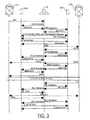
- FIG. 3 is a schematic diagram illustrating a simplified signalling sequence for connection setup using cached SVCs when a connection request originates at an end device interface having an instance of a caching manager designated as a master of the cache pool.
- the ATM network 20 (FIG. 1) is connected to an associated call manager 38 which transparently managers call connections between the telephone switching offices 22, 24 without direct interaction with the ATM switches.
- the arrangement and operation of such a network is described in Applicant's United States Patent Application entitled TRANSIT TRUNK SUBNETWORK which was filed on 23 September 1998 and assigned application Serial No. 09/158855.
- the edge device 26M is the master of a cache pool shared with the edge device 26S.
- Edge device 26M serves end office 22a and edge device 26S serves end office 22b.
- a call originates at end office 22a.
- the end office 22a formulates an SS7 Initial Address Message (IAM) and forwards the IAM over the SS7 network to the call manager 38.
- IAM Initial Address Message
- the call manager 38 extracts information from the IAM and determines from the called number that the call should be terminated at end office 22b using edge device interface 26S.
- the call manager 38 uses the information extracted from the IAM to locate the edge device interface to handle the call origination and sends an IAM advisory message to the edge device interface 26M.
- the edge device interface 26M On receipt of the IAM advisory message, the edge device interface 26M verifies the availability of resources and responds with an IAM ACK (acknowledge). The call manager 38 then sends on IAM advisory to the terminating edge device interface 26S which performs a verification of the availability of resources and responds with an IAM ACK. Immediately thereafter, call manager 38 sends a connection request to the edge device interfaces 26S, 26M.
- the connection request message may be sent exclusively to the terminating end at edge device interface 26S or sent to each of the edge device interfaces 26S, 26M. For reasons that will be understood by those skilled in the art, it is advantageous to effect backward call setup through the ATM network if the ATM network is organized in a plurality of subnets, respectively managed by a call manager 38.
- a terminating edge device interface 26 has all the information required to set up a backward connection through the ATM network whereas the edge device serving the originating switch does not. It should also be noted that depending on the organization of the ATM network 20 (FIG. 1) backwards setup may not be required or advantageous and is not essential to the operation of the invention.
- the connection request message is sent to each of the edge device interfaces 26S, 26M.
- the connection request message sent to edge device interface 26S includes:
- connection request message sent to edge device interface 26M includes:
- the edge device interface 26S On receipt of the Connection Request message, the edge device interface 26S, being a slave in the cache pool relationship formulates an SVC Request message and transmits it to the edge device interface master 26M.
- a System Management (OAM) cell may be used for this purpose.
- the OAM cell may be sent over any idle SVC to the cache master end. If no idle SVC is available, the edge device interface 26S may, for example, perform one of the following:
- the cache manager at edge device interface 26M selects an available SVC from the cache and sends a Synchronize message over the SVC to inform the edge device interface 26S that that SVC is to be used to serve the call.
- the edge device interface 26S responds to the Synchronize message with a SynchAck message.
- the call manager 38 forwards the IAM to the terminating end office 22b.
- end office 22b verifies that the called party line is available.
- the end office 22b then returns an Address Complete Message (ACM) to the call manager 38.
- ACM Address Complete Message
- call manager 38 forwards an ACM advisory message to the respective edge device interfaces 26S, M and receives an ACM ACK in return.
- the call manager 38 On receipt of the respective ACM ACK messages, the call manager 38 forwards the ACM over the SS7 network to the end office 22a. When the called party answers, end office 22b formulates an Answer Message (ANM) which it forwards over the SS7 network 30 to the call manager 38. As with the ACM message, the call manager 38 responds to receipt of the ANM message by sending an ANM advisory message to each of edge device interfaces 26S, M and receives an ANM ACK in return. Call manager 38 then modifies the ANM message and forwards it to the end office 22a. Thereafter, conversation ensues across the completed call path.
- ACM Answer Message
- the called party goes on-hook first, so an SS7 Release (REL) message is sent from end office 22b to the call manager 38.
- the call manager 38 responds by sending an REL advisory message to the respective edge device interfaces 26S, M and receives an REL ACK message in return.
- the call manager 38 modifies the REL message and forwards it to the end office 22a.
- the call manager 38 then returns a Release complete (RLC) message to the end office 22b to confirm the release.
- End office 22a likewise returns an RLC message to the call manager 38.
- the call manager 38 sends an RLC advisory message to each of the edge device interfaces 26S, M.
- the cache manager at edge device interface 26M examines the size of the cache pool and determines that the SVC should be cached, as will be explained below with reference to FIGs. 7-9. Consequently, the cache manager at edge device interface 26M returns an OAM cell instructing the slave at edge device interface 26S to cache the SVC for later use.
- the signals exchanged in the examples shown in FIG. 3 use System Management OAM cells sent through the ATM network for inter-device signalling, other mechanisms may be used such as a control channel (not illustrated) or a Generic Application Transport (GAT) protocol which has been proposed as a messaging protocol standard to the ATM Forum.
- GAT Generic Application Transport
- FIG. 4 shows the same call sequence shown in FIG. 3 with the exception that a cached SVC is not available and the cache master 26M is required to establish a new SVC to serve the call.
- the SVC setup may be accomplished by the slave if no idle and available SVCs exist in the cache. In this example, however, the slave at edge device interface 26S inserts an OAM cell-setup request in an in-use SVC and the cache manager master at edge device interface 26M sets up the new SVC.
- the setup is accomplished by a Setup message sent to the ATM network from edge device interface 26S.
- the ATM network does the necessary routing and sends an ATM Setup message to edge device interface 26S.
- the edge device interface 26S responds with a Connect message to the ATM network which responds by routing an ATM Connect message back to the edge device interface 26M.
- the edge device interface 26M sends a Synchronize message back to the edge device interface 26S and call processing continues as described above with reference to FIG. 3.
- FIG. 5 is a schematic diagram of a signalling sequence illustrating an instance in which a call request originates at an edge device interface which is designated as slave manager of the cache pool.
- the sequence in FIG. 5 is substantially the same as the sequence in FIG. 3 with the exception that edge device interface 26M is the terminating edge device interface for a call which originated at end office 22b and terminates at end office 22a. Since the call sequences are substantially identical, a description of each step is not provided. Attention is directed to the Synchronize message which is sent from edge device interface 26M to the edge device interface 26S. Since the master of the cache pool is the terminating edge device for the call, it inspects the cache table and selects an idle and available cached SVC. It then sends the Synchronize message over the selected SVC to the edge device interface 26S which returns a SynchAck message, as explained above with reference to FIG. 3. Thereafter, the call proceeds as described above.
- the cache managers of the cache pool may also have a peer-to-peer relationship.
- FIG. 6 is a schematic diagram illustrating a signalling sequence for connection setup when the cache managers at each of the edge device interfaces are peers.
- a call originates at end office 22a which formulates an IAM that is forwarded to the call manager 38.
- the call manager 38 extracts call information from the IAM and forwards an IAM advisory to each of edge device interface 26O (originating end) and edge device interface 26T (terminating end) .
- the respective edge device interfaces 26O, T verify resource availability and return the IAM ACK messages as described above. Thereafter, the call manager 38 sends a Connection Request message to each of edge device interfaces 26T and 26O.
- the cache manager at edge device interface 26T selects an SVC from cache and sends a Synchronize message to the edge device interface 26O. Since the edge device interfaces 26T, 26O operate as peers, a condition equivalent to "glare" can develop in which two cache managers select the same SVC at the same time for different calls. In the example shown in FIG. 6, the cache managers at edge device 26T and 26O select the same SVC at the same time. There are many ways in which such glare conditions can be resolved. In the example shown, the edge device interface 26O returns a Synch Denied message over the selected SVC, and the edge device interface 26T immediately selects another available SVC from the cache and repeats the Synchronize message over the newly selected SVC.
- FIG. 7 is a flow chart illustrating a general overview of a preferred caching algorithm in accordance with the invention.
- the caching manager 39 waits for a connection request to be received from call manager 38, as described above.
- the call manager determines in step 102 whether the cache contains an idle and available cached SVC to serve the connection request. If a cached SVC is available, the SVC is removed from cache in step 104 and mapped to the connection in step 106. If the cache is empty, the cache manager requests from a new SVC from the ATM network in step 108. If the ATM network has capacity to create the new SVC, it is mapped to the connection in step 106.
- the cache manager checks cache once again in step 110 since there is a possibility that a call release has returned a connection to the cache during the time that the cache manager was waiting for a response from the ATM network respecting the setup of a new SVC. If the second inspection of the cache indicates that a cached SVC is available, it is removed from cache in step 104 and mapped to the connection in step 106. Otherwise, the connection is blocked in step 112 and the cache manager returns to the connection monitoring process in step 100.
- the cache manager updates link loading, switch loading and traffic level registers in step 114.
- the link loading, switching loading and traffic level registers are used in cache size management, as will be explained below.
- cache size is inspected in step 116 to determine whether the number of cached SVCs is less than a minimum cache size.
- a minimum and a maximum cache size are provided to each cache manager 38. Preferably, these values are provided to the cache manager by a central cache policy manager, as will be described below.
- the minimum and maximum cache values may also be supplied by a system administrator or determined dynamically by a central or local process.
- step 116 If cache size is determined to be less than the minimum cache size in step 116, the link load is checked in step 118 to determine whether it is greater than a predetermined value. If it is, the cache manager returns to the monitoring process in step 100. Otherwise, in step 120, the cache manager requests a new SVC setup from the ATM network and adds the SVC to the cache in step 122.
- a separate process of the cache manager 38 monitors connection releases in step 124.
- the cache manager 38 detects that a connection has been released, the cache manager checks in step 126 to determine whether cache is full, i.e., whether cache size is greater than the maximum cache size. If the cache is full, the SVC is released through the ATM network in step 128. If the cache is not full, in step 130 the caching manager adds the SVC to the cache and returns to the connection release monitoring process in step 130.
- a third process executed by the cache manager 38 is responsible for cache size management.
- the cache size management process executes a simple algorithm every "n" calls or each time interval "T", or both. If the algorithm is executed every n calls, the cache size adaptation frequency changes with traffic load. If the algorithm is executed after the time interval T has elapsed, the algorithm is executed at a constant frequency. With a combined approach, the algorithm is executed in response to traffic load when traffic load is high and at predefined intervals when traffic load is low. In step 132, the parameter(s) determining the cache size management frequency is monitored and the cache management algorithm is executed when the parameter(s) meets the predetermined criteria. When the algorithm is executed, the link load register is compared with a predetermined limit to determine whether link load is too high.
- step 138 the cache size is decreased in step 138 if the cache size is greater than the cache size minimum.
- the switch load or traffic variation are examined in step 136. Either switch load or traffic variation may be used for a comparative examination to determine whether current switch load or current traffic load is increasing or decreasing with respect to a last time the algorithm was executed. For this purpose, the switch load and traffic level updated in step 114 is compared with a corresponding value saved when the algorithm was last executed.
- step 136 If a decrease greater than a predetermined value "X1" is detected in step 136, the cache size is decreased by one if in step 138 the cache size is greater than minimum cache size. If in step 136 the switch load or traffic load is determined to have increased beyond a second predetermined value "X2", then cache size is incremented by one in step 140 unless the cache size is already at maximum cache size.
- This algorithm dynamically adapts cache size to fluctuating traffic loads in order to ensure a dynamic balance of the use of bandwidth and switching resources by adding SVCs when bandwidth usage is low with respect to switch resource usage and removing SVCs from the pool when bandwidth usage is high with respect to switch resource usage.
- FIG. 8 is a flowchart illustrating the general algorithm in FIG. 7 adapted to provide a self-managing system for cache control using grade or quality of service levels and call setup delay control parameters.
- the first process is substantially identical to the general algorithm described above with the exception that step 114 (FIG. 7) is converted into steps 114a and step 114b.
- step 114a the cache manager adds a setup delay for the connection to a delay register.
- step 114b the cache manager updates a grade of service (GOS) value which is a measure of the number of connection attempts blocked, or a quality of service (QOS) value which is a measure of the transmission quality of a connection which may be measured using a number techniques well known in the art. Either GOS or QOS, or both, can be used in cache management, as will be explained below.
- GOS grade of service
- QOS quality of service
- the cache manager operates in steps 124-130 exactly as described above with reference to FIG. 7.
- the cache management algorithm is executed every N th connection requests or each time interval T, or both, as described above.
- the appropriate variable(s) are monitored to determine when the cache management algorithm should be executed.
- GOS or QOS are examined to determine whether they are greater than a predetermined value "%". If so, in step 146, the cache size is decreased by one when the cache size is greater than cache size minimum. If GOS or QOS do not exceed a predetermined value, the average connection setup delay is examined in step 144 to determine whether the average setup delay is less than a predetermined value identified as "LowB" or greater than a predetermined value identified as "UpB" in step 144.
- the cache size is decreased by one in step 146, if it is greater than cache size minimum. If the average setup delay is less than UpB, the cache size is incremented by one in step 148 if it less than cache size maximum.
- one cached SVC may be removed from the cache and released through the ATM network. Alternatively, the process may wait a predetermined time to determine whether a one of the cached SVCs is used for a connection. If a cached SVC is used for connection, the SVC is not released until an SVC is to be returned to the cache, at which time the release is effected.
- one SVC setup may be requested from the ATM network and the SVC set up is added to the cache.
- the cache manager may wait a predetermined period of time to determine whether a connection release will add another connection to the cache.
- the GOS, QOS and setup delay registers are cleared so that new values can be accumulated in steps 114a and 114b, as described above.
- the grade of service is used to capture the link load.
- Grade of service is normally a measure of connection request blocking that has been used for provisioning the traditional switched telephone network for decades.
- the average SVC setup delay is used to capture switch load and route traffic fluctuation simultaneously. An increase in switch load or an increase in route traffic will each increase the connection setup delay.
- the call setup delay can be measured using timers. For example, a timer can be started when a new SVC request is sent and read when the connection setup is complete. GOS is most simply computed by measuring the number of connection requests blocked while counting the total number of connection requests received.
- FIG. 9 is flowchart illustrating the general algorithm shown in FIG. 7 adapted for using the number of waiting connection requests and a GOS or QOS as control parameters for governing cache size.
- the first and second concurrent processes are identical to that shown in FIGs. 7 and 8 with the exception that in step 114c an outstanding connection request counter is updated and in step 114d, the GOS and QOS registers are updated.
- step 152 the number of outstanding connection requests accumulated in step 114c is compared with predetermined values "LowB" and "UpB" to determine whether the number of outstanding connection requests is less than LowB or greater than UpB. If the number of outstanding connection requests is greater than LowB, then cache size is decreased by one, if the cache size is greater than the cache size minimum. If the number of outstanding connection requests is greater than the value of UpB then the cache size is increased by one, if the cache size is less than maximum cache size, as shown in step 148. In step 150, the registers are cleared so that fresh accumulations,are available for the next time the cache size management algorithm is executed.
- a condition hereinafter referred to "cache fragmentation" can occur when a very large telephone switching office is connected to an ATM network.
- the condition arises because typically the edge device interfaces 26 have a finite trunk capacity which is not equal to a trunk capacity of a large time division multiplexed (TDM) switch. Consequently, as shown in FIG. 10, when a large TDM switch 40 is connected to the ATM network 20 a plurality of edge device interfaces 26 are required to serve the switch.
- TDM time division multiplexed
- it is preferable that a single logical trunk group 42 is used for the connection because it simplifies maintenance on the TDM switch 40 and significantly reduces operations and maintenance costs.
- Cache fragmentation occurs because each of the edge device interfaces 26 connect to TDM 40 and require a cache pool to each edge device 26 connected to other TDM switches 44.
- FIG. 11 is a schematic diagram illustrating the effects of cache fragmentation on edge device interfaces that serve small TDM switches.
- the edge device interface 26 for TDM switch 44 shown in FIG. 11, must support three cache pools to serve TDM 40 in order to take advantage of the benefits offered by the single logical trunk group 42 for TDM switch 40.
- the number of instances of the cache manager on an edge device interface 26 may become unwieldy. Consequently, it is desirable to provide a mechanism for controlling cache fragmentation at the edge device interfaces 26.
- FIG. 12 shows one method of controlling edge device interfaces in which multiple trunk groups 46a-46c are used to connect the TDM 40 to the edge device interfaces 26a, 26b and 26c.
- cache fragmentation is implemented at the expense of increased management on the TDM switch 40.
- routing tables on the TDM 40 route connection requests over the appropriate trunk group in a manner well known in the art. Consequently, management at TDM 40 is no more complex than is required in the switched telephone network as it currently exists and cache fragmentation is correspondingly minimized.
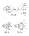
- FIG. 13 shows an alternate solution to reducing cache fragmentation.
- the TDM 40 is connected to the edge devices 26a-26c using a single logical trunk group 42 but the edge device interfaces 26a-26c are interconnected by inter-device bridges 48 and managed as a single large edge device interface. Consequently, only one cache pool 36 is required for each other edge device interface in the subnetwork. If a call is routed by TDM 40 to edge device 26a but the cache pool required to serve the call is managed by edge device interfaces 26c, 26a routes the call over the inter-device bridges 48 to edge device interface 26c which completes the connection processing in a manner described above.
- FIG. 14 illustrates another arrangement which permits a large TDM switch 40 to be connected by a single logical trunk group 42 to a plurality of edge devices 26a-26c.
- an ATM switch 50 is used to consolidate and manage cache pools 36 so that cache fragmentation is eliminated. While this solution requires more capital investment than the other solutions described above, it provides another alternative for reducing cache fragmentation.
Landscapes
- Engineering & Computer Science (AREA)
- Computer Networks & Wireless Communication (AREA)
- Signal Processing (AREA)
- Data Exchanges In Wide-Area Networks (AREA)
- Telephonic Communication Services (AREA)
Applications Claiming Priority (2)
| Application Number | Priority Date | Filing Date | Title |
|---|---|---|---|
| US09/165,189 US6822961B1 (en) | 1998-10-02 | 1998-10-02 | Method and apparatus for reduction of call setup rate in an ATM network |
| US165189 | 1998-10-02 |
Publications (2)
| Publication Number | Publication Date |
|---|---|
| EP0991294A2 true EP0991294A2 (fr) | 2000-04-05 |
| EP0991294A3 EP0991294A3 (fr) | 2002-09-11 |
Family
ID=22597843
Family Applications (1)
| Application Number | Title | Priority Date | Filing Date |
|---|---|---|---|
| EP99307704A Withdrawn EP0991294A3 (fr) | 1998-10-02 | 1999-09-29 | Procédé et dispositif pour faciliter l'établissement d'un appel dans un reseau ATM |
Country Status (4)
| Country | Link |
|---|---|
| US (1) | US6822961B1 (fr) |
| EP (1) | EP0991294A3 (fr) |
| JP (1) | JP2000115200A (fr) |
| CA (1) | CA2282929A1 (fr) |
Cited By (3)
| Publication number | Priority date | Publication date | Assignee | Title |
|---|---|---|---|---|
| EP1009194A2 (fr) | 1998-12-07 | 2000-06-14 | Nortel Networks Corporation | Centrale téléphonique pour voix en mode hybride ATM et TDM et procédé pour compléter des appels entre des commutateurs utilisant cette centrale |
| WO2001011835A1 (fr) * | 1999-08-06 | 2001-02-15 | Tellabs Operations, Inc. | Gestion de largeur de bande dans un systeme de communications utilisant des reseaux a commutation de circuits et a commutation de paquets |
| CN100459770C (zh) * | 2006-04-12 | 2009-02-04 | 华为技术有限公司 | 提高无线网络控制器与基站之间接口带宽利用效率的方法 |
Families Citing this family (28)
| Publication number | Priority date | Publication date | Assignee | Title |
|---|---|---|---|---|
| JP3508669B2 (ja) * | 2000-01-18 | 2004-03-22 | 日本電気株式会社 | Atmコネクション帯域制御方法 |
| AU2001231039A1 (en) * | 2000-01-20 | 2001-07-31 | Mci Worldcom, Inc. | Intelligent network and method for providing voice telephony over atm and alias addressing |
| US6343065B1 (en) * | 2000-01-20 | 2002-01-29 | Sbc Technology Resources, Inc. | System and method of measurement-based adaptive caching of virtual connections |
| EP1225785A1 (fr) * | 2000-10-27 | 2002-07-24 | Alcatel | Unité de commande d'accès |
| US7188145B2 (en) | 2001-01-12 | 2007-03-06 | Epicrealm Licensing Llc | Method and system for dynamic distributed data caching |
| US7035911B2 (en) | 2001-01-12 | 2006-04-25 | Epicrealm, Licensing Llc | Method and system for community data caching |
| ATE422965T2 (de) * | 2001-03-09 | 2009-03-15 | Gen Probe Inc | Verfahren zum entnehmen von flüssigkeit aus einem behälter mit durchdringbarem verschluss |
| US6934952B2 (en) * | 2001-04-09 | 2005-08-23 | International Business Machines Corporation | Method and apparatus for managing multiple instances of server code on a machine |
| SE519612C2 (sv) * | 2001-07-09 | 2003-03-18 | Ericsson Telefon Ab L M | Telekommunikationssystem med ATM-kärnnät och minst en Media Gateway som hanterar TDM-gränssnitt |
| US8635305B1 (en) * | 2001-12-19 | 2014-01-21 | Cisco Technology, Inc. | Mechanisms for providing differentiated services within a web cache |
| US7167448B2 (en) * | 2002-02-04 | 2007-01-23 | Sun Microsystems, Inc. | Prioritization of remote services messages within a low bandwidth environment |
| US20030163544A1 (en) * | 2002-02-04 | 2003-08-28 | Wookey Michael J. | Remote service systems management interface |
| US20030149771A1 (en) * | 2002-02-04 | 2003-08-07 | Wookey Michael J. | Remote services system back-channel multicasting |
| US20030177259A1 (en) * | 2002-02-04 | 2003-09-18 | Wookey Michael J. | Remote services systems data delivery mechanism |
| US20030149740A1 (en) * | 2002-02-04 | 2003-08-07 | Wookey Michael J. | Remote services delivery architecture |
| DE10207976B4 (de) * | 2002-02-25 | 2004-04-15 | Siemens Ag | Verfahren zum netzübergreifenden Verbindungsaufbau und Netzübergangseinrichtung zur Realisierung des Verfahrens |
| US7272141B1 (en) * | 2002-02-28 | 2007-09-18 | At&T Bls Intellectual Property, Inc. | System and method for serializing bulk virtual circuit connection requests |
| US20030212738A1 (en) * | 2002-05-10 | 2003-11-13 | Wookey Michael J. | Remote services system message system to support redundancy of data flow |
| US7260623B2 (en) | 2002-06-27 | 2007-08-21 | Sun Microsystems, Inc. | Remote services system communication module |
| US7181455B2 (en) * | 2002-06-27 | 2007-02-20 | Sun Microsystems, Inc. | Bandwidth management for remote services system |
| US8266239B2 (en) * | 2002-06-27 | 2012-09-11 | Oracle International Corporation | Remote services system relocatable mid level manager |
| US7240109B2 (en) * | 2002-06-27 | 2007-07-03 | Sun Microsystems, Inc. | Remote services system service module interface |
| US20040190531A1 (en) * | 2002-08-20 | 2004-09-30 | Pierre-Yves Sibille | Bearer connection signaling in a distributed architecture |
| US7403992B2 (en) * | 2003-07-10 | 2008-07-22 | Nokia Corporation | Adaptive connection cache for communication networks |
| US8570898B1 (en) * | 2008-10-24 | 2013-10-29 | Marvell International Ltd. | Method for discovering devices in a wireless network |
| US10405193B1 (en) | 2018-06-28 | 2019-09-03 | At&T Intellectual Property I, L.P. | Dynamic radio access network and intelligent service delivery for multi-carrier access for 5G or other next generation network |
| US11625327B2 (en) * | 2019-12-10 | 2023-04-11 | EMC IP Holding Company LLC | Cache memory management |
| US11595247B1 (en) * | 2021-10-06 | 2023-02-28 | At&T Intellectual Property I, L.P. | Subscriber feedback mechanism for real-time network service upgrade |
Family Cites Families (14)
| Publication number | Priority date | Publication date | Assignee | Title |
|---|---|---|---|---|
| US5179556A (en) * | 1991-08-02 | 1993-01-12 | Washington University | Bandwidth management and congestion control scheme for multicast ATM networks |
| JP2646948B2 (ja) | 1992-12-25 | 1997-08-27 | 日本電気株式会社 | パケット網におけるシグナリング方式 |
| JP2518515B2 (ja) | 1993-05-27 | 1996-07-24 | 日本電気株式会社 | 高速コネクション設定パケット交換機 |
| US5528592A (en) | 1994-01-27 | 1996-06-18 | Dsc Communications Corporation | Method and apparatus for route processing asynchronous transfer mode cells |
| US5455826A (en) * | 1994-06-28 | 1995-10-03 | Oezveren; Cueneyt M. | Method and apparatus for rate based flow control |
| DE19502414C1 (de) | 1995-01-26 | 1996-02-08 | Siemens Ag | Verfahren und Anordnung zum schnellen Durchschalten von virtuellen Verbindungen in ATM-Kommunikationssystemen |
| US5787086A (en) * | 1995-07-19 | 1998-07-28 | Fujitsu Network Communications, Inc. | Method and apparatus for emulating a circuit connection in a cell based communications network |
| JPH1075247A (ja) * | 1996-08-29 | 1998-03-17 | Toshiba Corp | ノード装置及び仮想コネクション管理方法 |
| EP0836306B1 (fr) * | 1996-10-10 | 2012-07-04 | Hewlett-Packard Company (a Delaware Corporation) | Système permettant plusieurs circuits virtuels entre deux entités |
| US6094687A (en) * | 1998-01-17 | 2000-07-25 | Fore Systems, Inc. | System and method for connecting source nodes and destination nodes regarding efficient quality of services route determination using connection profiles |
| US6252857B1 (en) * | 1998-03-04 | 2001-06-26 | At&T Corp. | Method and apparatus for provisioned and dynamic quality of service in a communications network |
| JPH11266258A (ja) * | 1998-03-17 | 1999-09-28 | Fujitsu Ltd | Atmネットワーク装置 |
| US6275493B1 (en) * | 1998-04-02 | 2001-08-14 | Nortel Networks Limited | Method and apparatus for caching switched virtual circuits in an ATM network |
| US6195714B1 (en) * | 1998-06-08 | 2001-02-27 | Nortel Networks Limited | System for transferring STM calls through ATM network by converting the STM calls to ATM and vice versa at the edge nodes of ATM network |
-
1998
- 1998-10-02 US US09/165,189 patent/US6822961B1/en not_active Expired - Lifetime
-
1999
- 1999-09-21 CA CA002282929A patent/CA2282929A1/fr not_active Abandoned
- 1999-09-29 EP EP99307704A patent/EP0991294A3/fr not_active Withdrawn
- 1999-10-01 JP JP28100699A patent/JP2000115200A/ja active Pending
Cited By (3)
| Publication number | Priority date | Publication date | Assignee | Title |
|---|---|---|---|---|
| EP1009194A2 (fr) | 1998-12-07 | 2000-06-14 | Nortel Networks Corporation | Centrale téléphonique pour voix en mode hybride ATM et TDM et procédé pour compléter des appels entre des commutateurs utilisant cette centrale |
| WO2001011835A1 (fr) * | 1999-08-06 | 2001-02-15 | Tellabs Operations, Inc. | Gestion de largeur de bande dans un systeme de communications utilisant des reseaux a commutation de circuits et a commutation de paquets |
| CN100459770C (zh) * | 2006-04-12 | 2009-02-04 | 华为技术有限公司 | 提高无线网络控制器与基站之间接口带宽利用效率的方法 |
Also Published As
| Publication number | Publication date |
|---|---|
| JP2000115200A (ja) | 2000-04-21 |
| EP0991294A3 (fr) | 2002-09-11 |
| US6822961B1 (en) | 2004-11-23 |
| CA2282929A1 (fr) | 2000-04-02 |
Similar Documents
| Publication | Publication Date | Title |
|---|---|---|
| US6822961B1 (en) | Method and apparatus for reduction of call setup rate in an ATM network | |
| US6260071B1 (en) | Method and apparatus for automatic routing of circuit switched data connections based upon stored behavorial information | |
| US6470029B1 (en) | Bandwidth control method in a network system | |
| EP0999674B1 (fr) | Procédé pour fournir de la qualité de service au trafic sensible au délai sur des réseaux IP | |
| US6011804A (en) | Dynamic bandwidth reservation for control traffic in high speed packet switching networks | |
| JP4376457B2 (ja) | 構内または広域ネットワークのサービスの保証された品質を与える方法および装置 | |
| US6519257B1 (en) | ATM telecommunications systems and method for routing narrow band traffic | |
| JPH1084349A (ja) | ネットワーク接続品質制御方式 | |
| US7050421B1 (en) | ATM network providing transparently narrowband based telephony services without requiring ATM-switching | |
| US8547849B2 (en) | ATM telecommunications systems and method for routing narrow band traffic | |
| US6721322B1 (en) | System and method for establishing dynamic high usage trunk groups | |
| CA2381464A1 (fr) | Gestion de largeur de bande dans un systeme de communications utilisant des reseaux a commutation de circuits et a commutation de paquets | |
| US6917625B1 (en) | Intelligent peripheral concentrator | |
| JPH09307557A (ja) | Atm網におけるレート制御方法 | |
| JP3470079B2 (ja) | 通話のルーティング方法 | |
| KR100538876B1 (ko) | 패킷 교환기와 패킷 관문 교환기간의 링크 채널 관리 방법 | |
| KR0123255B1 (ko) | 완전 분산형 에이티엠(atm) 교환 시스템에서의 점대점 단방향 경로 제어 방법 | |
| JP3059101B2 (ja) | Atmスイッチ | |
| JP3561163B2 (ja) | Atm通信網 | |
| JP4413330B2 (ja) | 高使用幹線グループを動的に確立するためのシステム及び方法 | |
| KR19980061780A (ko) | Atm기반의 개인휴대통신망에서의 대역폭 할당 방법 | |
| JPH1013426A (ja) | ループ型atmネットワークにおける仮想パス自動設定方式 | |
| KR19980043602A (ko) | 착신측 사용자-망 접면에서 사용자-사용자 교환 가상 경로 연결의 제공방법 | |
| EP1086562A1 (fr) | Reseau de donnees a plusieurs centres de commutation | |
| JPH11509704A (ja) | 通信回路網内に接続を完結させる方法及び検出ユニット |
Legal Events
| Date | Code | Title | Description |
|---|---|---|---|
| PUAI | Public reference made under article 153(3) epc to a published international application that has entered the european phase |
Free format text: ORIGINAL CODE: 0009012 |
|
| AK | Designated contracting states |
Kind code of ref document: A2 Designated state(s): AT BE CH CY DE DK ES FI FR GB GR IE IT LI LU MC NL PT SE |
|
| AX | Request for extension of the european patent |
Free format text: AL;LT;LV;MK;RO;SI |
|
| RAP1 | Party data changed (applicant data changed or rights of an application transferred) |
Owner name: NORTEL NETWORKS LIMITED |
|
| PUAL | Search report despatched |
Free format text: ORIGINAL CODE: 0009013 |
|
| AK | Designated contracting states |
Kind code of ref document: A3 Designated state(s): AT BE CH CY DE DK ES FI FR GB GR IE IT LI LU MC NL PT SE |
|
| AX | Request for extension of the european patent |
Free format text: AL;LT;LV;MK;RO;SI |
|
| 17P | Request for examination filed |
Effective date: 20030212 |
|
| AKX | Designation fees paid |
Designated state(s): DE FR GB SE |
|
| RAP1 | Party data changed (applicant data changed or rights of an application transferred) |
Owner name: NORTEL NETWORKS LIMITED |
|
| 17Q | First examination report despatched |
Effective date: 20050628 |
|
| STAA | Information on the status of an ep patent application or granted ep patent |
Free format text: STATUS: THE APPLICATION IS DEEMED TO BE WITHDRAWN |
|
| 18D | Application deemed to be withdrawn |
Effective date: 20051109 |