EP1009194A2 - Centrale téléphonique pour voix en mode hybride ATM et TDM et procédé pour compléter des appels entre des commutateurs utilisant cette centrale - Google Patents
Centrale téléphonique pour voix en mode hybride ATM et TDM et procédé pour compléter des appels entre des commutateurs utilisant cette centrale Download PDFInfo
- Publication number
- EP1009194A2 EP1009194A2 EP99309782A EP99309782A EP1009194A2 EP 1009194 A2 EP1009194 A2 EP 1009194A2 EP 99309782 A EP99309782 A EP 99309782A EP 99309782 A EP99309782 A EP 99309782A EP 1009194 A2 EP1009194 A2 EP 1009194A2
- Authority
- EP
- European Patent Office
- Prior art keywords
- call
- central office
- office
- inter
- central
- Prior art date
- Legal status (The legal status is an assumption and is not a legal conclusion. Google has not performed a legal analysis and makes no representation as to the accuracy of the status listed.)
- Granted
Links
- 238000000034 method Methods 0.000 title claims description 22
- 239000004744 fabric Substances 0.000 claims description 37
- 230000011664 signaling Effects 0.000 claims description 27
- 238000012546 transfer Methods 0.000 claims description 10
- 230000008859 change Effects 0.000 claims description 2
- 230000002093 peripheral effect Effects 0.000 claims 1
- 238000012545 processing Methods 0.000 abstract description 9
- 230000008901 benefit Effects 0.000 abstract description 5
- 238000012423 maintenance Methods 0.000 abstract description 4
- 230000009467 reduction Effects 0.000 abstract description 2
- 241000036569 Carp sprivivirus Species 0.000 description 33
- 238000010586 diagram Methods 0.000 description 11
- 238000000765 microspectrophotometry Methods 0.000 description 11
- 238000013519 translation Methods 0.000 description 11
- 108091006146 Channels Proteins 0.000 description 7
- 230000004044 response Effects 0.000 description 7
- 230000002860 competitive effect Effects 0.000 description 3
- 238000004880 explosion Methods 0.000 description 3
- 230000008569 process Effects 0.000 description 3
- 230000001360 synchronised effect Effects 0.000 description 3
- 238000006243 chemical reaction Methods 0.000 description 2
- 102100032467 Transmembrane protease serine 13 Human genes 0.000 description 1
- 238000004891 communication Methods 0.000 description 1
- 238000011161 development Methods 0.000 description 1
- 230000018109 developmental process Effects 0.000 description 1
- 230000000694 effects Effects 0.000 description 1
- 230000000763 evoking effect Effects 0.000 description 1
- 239000000284 extract Substances 0.000 description 1
- 238000009472 formulation Methods 0.000 description 1
- 230000000977 initiatory effect Effects 0.000 description 1
- 238000013507 mapping Methods 0.000 description 1
- 239000000203 mixture Substances 0.000 description 1
- 238000012986 modification Methods 0.000 description 1
- 230000004048 modification Effects 0.000 description 1
- 235000019799 monosodium phosphate Nutrition 0.000 description 1
- 230000003287 optical effect Effects 0.000 description 1
- 230000001105 regulatory effect Effects 0.000 description 1
- 238000012360 testing method Methods 0.000 description 1
- 238000012795 verification Methods 0.000 description 1
Images


Classifications
-
- H—ELECTRICITY
- H04—ELECTRIC COMMUNICATION TECHNIQUE
- H04L—TRANSMISSION OF DIGITAL INFORMATION, e.g. TELEGRAPHIC COMMUNICATION
- H04L49/00—Packet switching elements
- H04L49/60—Software-defined switches
- H04L49/606—Hybrid ATM switches, e.g. ATM&STM, ATM&Frame Relay or ATM&IP
-
- H—ELECTRICITY
- H04—ELECTRIC COMMUNICATION TECHNIQUE
- H04L—TRANSMISSION OF DIGITAL INFORMATION, e.g. TELEGRAPHIC COMMUNICATION
- H04L12/00—Data switching networks
- H04L12/64—Hybrid switching systems
- H04L12/6402—Hybrid switching fabrics
-
- H—ELECTRICITY
- H04—ELECTRIC COMMUNICATION TECHNIQUE
- H04Q—SELECTING
- H04Q11/00—Selecting arrangements for multiplex systems
- H04Q11/04—Selecting arrangements for multiplex systems for time-division multiplexing
- H04Q11/0428—Integrated services digital network, i.e. systems for transmission of different types of digitised signals, e.g. speech, data, telecentral, television signals
- H04Q11/0478—Provisions for broadband connections
-
- H—ELECTRICITY
- H04—ELECTRIC COMMUNICATION TECHNIQUE
- H04Q—SELECTING
- H04Q3/00—Selecting arrangements
- H04Q3/0016—Arrangements providing connection between exchanges
- H04Q3/0025—Provisions for signalling
-
- H—ELECTRICITY
- H04—ELECTRIC COMMUNICATION TECHNIQUE
- H04L—TRANSMISSION OF DIGITAL INFORMATION, e.g. TELEGRAPHIC COMMUNICATION
- H04L12/00—Data switching networks
- H04L12/54—Store-and-forward switching systems
- H04L12/56—Packet switching systems
- H04L12/5601—Transfer mode dependent, e.g. ATM
- H04L2012/5614—User Network Interface
- H04L2012/5618—Bridges, gateways [GW] or interworking units [IWU]
-
- H—ELECTRICITY
- H04—ELECTRIC COMMUNICATION TECHNIQUE
- H04L—TRANSMISSION OF DIGITAL INFORMATION, e.g. TELEGRAPHIC COMMUNICATION
- H04L12/00—Data switching networks
- H04L12/54—Store-and-forward switching systems
- H04L12/56—Packet switching systems
- H04L12/5601—Transfer mode dependent, e.g. ATM
- H04L2012/5629—Admission control
- H04L2012/563—Signalling, e.g. protocols, reference model
-
- H—ELECTRICITY
- H04—ELECTRIC COMMUNICATION TECHNIQUE
- H04L—TRANSMISSION OF DIGITAL INFORMATION, e.g. TELEGRAPHIC COMMUNICATION
- H04L12/00—Data switching networks
- H04L12/54—Store-and-forward switching systems
- H04L12/56—Packet switching systems
- H04L12/5601—Transfer mode dependent, e.g. ATM
- H04L2012/5638—Services, e.g. multimedia, GOS, QOS
- H04L2012/5663—Support of N-ISDN
-
- H—ELECTRICITY
- H04—ELECTRIC COMMUNICATION TECHNIQUE
- H04L—TRANSMISSION OF DIGITAL INFORMATION, e.g. TELEGRAPHIC COMMUNICATION
- H04L12/00—Data switching networks
- H04L12/64—Hybrid switching systems
- H04L12/6418—Hybrid transport
- H04L2012/6475—N-ISDN, Public Switched Telephone Network [PSTN]
-
- H—ELECTRICITY
- H04—ELECTRIC COMMUNICATION TECHNIQUE
- H04L—TRANSMISSION OF DIGITAL INFORMATION, e.g. TELEGRAPHIC COMMUNICATION
- H04L12/00—Data switching networks
- H04L12/64—Hybrid switching systems
- H04L12/6418—Hybrid transport
- H04L2012/6481—Speech, voice
-
- H—ELECTRICITY
- H04—ELECTRIC COMMUNICATION TECHNIQUE
- H04Q—SELECTING
- H04Q2213/00—Indexing scheme relating to selecting arrangements in general and for multiplex systems
- H04Q2213/1338—Inter-exchange connection
Definitions
- the invention provides a central office for serving a plurality of subscriber lines, the central office being a telephone switch in a subnetwork with other central offices, the central office being equipped with a trunk interface to the public switched telephone network (PSTN) to permit the central office to receive calls from and transfer calls to the PSTN, and having a connection through at least one interface to an ATM backbone network which is used to transport payload traffic between the central offices in the network, CHARACTERIZED in that: the central office is a hybrid central office that serves as a virtual access tandem for other central offices in the subnetwork and virtually switches calls between the central offices through the ATM backbone network.
- PSTN public switched telephone network
- a method of completing an inter-office call originating at a central office in a subnetwork that includes a plurality of central offices which respectively serve a plurality of subscriber lines, each of the central offices being connected to an ATM backbone network by an interface that converts PCM data to ATM cells and vice versa, and at a central office that originates an inter-office call, an IAM relating to the inter-office call is formulated, the IAM containing a destination point code (DPC) of a call manager for the subnetwork, and the IAM is sent to the call manager, CHARACTERIZED in that:
- Each of the central offices in the subnetwork are preferably connected to the respective interfaces by a single large trunk group. Consequently, all inter-office calls originated at any one of the central offices, aside from the virtual access tandem, are routed to the large trunk group.
- a link set associated with the large trunk group points to the virtual access tandem.
- the virtual access tandem is responsible for the routing of all inter-office calls originated within or terminated within the subnetwork. Routing and translation tables for the subnetwork are therefore centralized in the virtual access tandem. Consequently, translation and routing table maintenance is centralized and more efficient. Furthermore, maintenance costs for the physical trunking at each central office are significantly reduced because the only trunking required is a large high capacity trunk, which may be a high speed optical link between each central office and the respective interface(s).
- the invention therefore provides a cost effective, efficient apparatus and method for relieving congestion in the PSTN which utilizes existent infrastructure in a very efficient and effective way.
- a hybrid central office for serving a plurality of subscriber lines while also serving as a virtual access tandem to a subnet of central offices connected to an ATM backbone network.
- each of the central offices of a subnetwork of central offices is connected by a trunk group to an ATM-based virtual access tandem, which is responsible for routing all calls originating in or terminating in the subnetwork.
- the architecture of the present invention benefits from an ability to provide a subnetwork in which the virtual access tandem is responsible for routing calls originating and terminating in the subnetwork.
- a further advantage achieved by a preferred embodiment of the present invention is that a telephone subnetwork is able to utilise an ATM backbone for completing switched telephone calls in which a plurality of central offices are connected to the ATM backbone by interfaces for converting pulse code modulated (PCM) data to ATM cells and vice versa, and one of the plurality of central offices is adapted to function as a virtual tandem for the subnetwork.
- PCM pulse code modulated
- a preferred embodiment of the present invention beneficially supports a method of completing an inter-office call originating at a central office in a subnetwork that includes a plurality of central offices which respectively serve a plurality of subscriber lines, and in which one of the central offices serves as a virtual tandem for the subnetwork.
- This invention relates to a subnetwork of telephone central offices connected through interfaces to an ATM backbone network.
- one of the central offices is adapted to serve as a virtual access tandem in the subnetwork so that inter-office trunk congestion is relieved in the subnetwork.
- FIG. 1 shows a portion of a subnetwork of central offices generally indicated by the reference 20 having a connection to an ATM backbone network 22.
- the subnetwork includes a plurality of central offices, only three of which are shown in FIG. 1 due to space constraints.
- One of the central offices is a hybrid central office 24 which serves a plurality of subscriber lines (not shown) while serving as a virtual access tandem to the subnetwork 20 of central office 26, each of which have a connection to the ATM backbone network 22.
- the hybrid central office 24 is also connected by existing time-division multiplexed (TDM) trunk groups 28 to the public switched telephone network (PSTN) 32 and to the other central offices 26.
- TDM time-division multiplexed
- the other central offices 26 are likewise interconnected by existing TDM trunk groups 28.
- a common channel signaling network 34 which typically operates under a Signaling System 7 (SS7) protocol which permits central offices to communicate with other nodes in the PSTN.
- SS7 Signaling System 7
- Each central office includes computing module (CM) 40 and a TDM switch fabric 41 which provides a link between subscriber lines and trunks for switching bearer traffic. Attached to the switch fabric 42 are digital trunk controllers (DTC) 42 that provide an interface to the PSTN 32, and inter-working multi-service platforms (IW-MSP) 44 that provide an interface to the ATM network 22.
- DTC digital trunk controllers
- IW-MSP inter-working multi-service platforms
- the computing module 40 has a signaling interface 46 with the ATM backbone network 22 to permit the computing module 40 to send messages to and receive messages from distributed access MSPs (DA-MSP) 48 which serve as interfaces to the ATM network 22 for the respective central offices 26.
- DSP distributed access MSP
- DSP distributed access MSP
- each of the central offices 26 is preferably connected to the ATM backbone network 22 by a single large trunk group 50. Configuring each of the end offices 26 with a single large trunk group has several distinct advantages as thoroughly explained in Applicant's co-pending patent application, the entirety of which is incorporated herein by reference.
- FIG. 2 is a schematic diagram of the computing module 40, shown in FIG. 1, and the principal functional components of the invention developed and added to enable the hybrid central office to function as a virtual access tandem to the subnetwork 20 shown in FIG. 1.
- the principal functional components added to the computing module 40 include inter-working translation and routing, connectivity control and messaging connectivity, each of which is briefly characterized as:
- interfaces are required between the central offices 24, 26 in the subnetwork 20 and the ATM backbone network 22.
- a principal function of the interfaces 44, 48 is to convert PCM data to ATM cells and vice versa.
- the interfaces are identified as IW-MSP 44 and DA-MSPs 48. The reason for the distinction is that there is some difference in functionality as will be explained below. It should be understood, however, that the interfaces 44, 48 may be implemented on the same platform and require substantially identical hardware functionality.
- the IW-MSP 44 provides an interface between the hybrid central office 24 and the ATM backbone 22. Its principal functions are to provide a bridge between the TDM fabric 41 and the ATM fabric 22. It is also responsible for initiating application instances which own inter-working bridges established through the TDM fabric 41 for inter-working calls and the TDM to ATM mapping associated with such calls.
- the IW-MSP also includes a functional entity hereinafter referred to as a "connection broker" which serves the functions of TDM component connection control; inter-working bridge connection control; ATM component connection control; the ATM-to-TDM interface and ATM-to-TDM path conversion.
- the IW-MSP 44 connection broker may provide SVC caching services for TDM fabric to ATM bridged calls.
- ATM SVCs are switched virtual connections through the ATM network, which are preferred over permanent virtual connections because they permit more efficient use of network resources.
- the majority of the connection broker functionality actually resides in the DA-MSP 48 which is preferably delegated as master of the SVC cache between itself and the IW-MSP 44, as will be explained below in more detail. It should be understood, however, that cached SVCs are not required and an SVC may be set up for each call routed through the ATM fabric 22.
- the IW-MSP 44 also supports an ATM signaling interface and the connection broker must be adapted to interact with an ATM signaling stack for the purposes of cached SVC control.
- the IW-MSP 44 preferably only terminates cached SVCs which are controlled by the DA-MSPs 48.
- the IW-MSP 44 supports a connection to the TDM switch fabric 41 and a connection to the ATM backbone network 22.
- a messaging interface between the IW-MSP 44 and the DA-MSPs 48 is also required. Call processing requires that messages be exchanged between the interfaces in order to start integrity checking, report integrity failures, etc.
- the DA-MSPs 48 likewise support a trunk interface connection to the central offices 26 and an ATM link to the ATM backbone network 22.
- the DA-MSPs 48 also include a functional component referred to as the connection broker.
- the connection broker preferably, but not necessarily, has responsibility for SVC caching to facilitate call set up response. In order to enable SVC caching, the connection broker must support an ATM messaging stack and an application programming interface (API) which permits the DA-SPM connection broker to maintain SVC caches.
- API application programming interface
- the DA-MSPs 48 also supports all the functionality described above with reference to the IW-MSPs, except for the inter-working bridge functionality.
- FIG. 3 is a simple flow chart illustrating the logic used by the call processing applications of the computing module 40 to make a call-type determination when a call request is received at the hybrid central office 24. Since existing inter-office trunks 28 (FIG. 1) may be used to complete calls in the subnetwork, the hybrid central office 24 must perform a call-type determination for each call request.
- an originating point code for example, of an initial address message (IAM) is examined to determine the originator fabric of a call. If the call is a TDM fabric call (originating in the PSTN or routed over inter-office trunks 28) an attempt is made to route the call on the TDM fabric in step 54. This is done in order to minimize the amount of inter-working between TDM and ATM sides.
- IAM initial address message
- the terminator fabric In order to route the call on the TDM fabric, the terminator fabric must be determined in step 56. If the terminator fabric is the TDM fabric, the call is determined to be a TDM fabric call in step 58. If the terminator fabric is ATM, the call is a hybrid call, as determined in step 60. A hybrid call is a TDM fabric-to-ATM or ATM-to-TDM fabric call. If the originator fabric determined in step 52 is ATM, an attempt is made is step 62 to route the call to the ATM fabric. In order to accomplish this, the terminator fabric is examined in step 64 and if the terminator fabric is TDM, the call is a hybrid call. Otherwise, the call is determined to be an ATM call in step 66.
- FIG. 4 is a schematic diagram of a subnetwork 20 in accordance with the invention showing signaling paths for signal messages involved in the set up of an inter-office call between a first central office 68 and a second central office 70 which are respectively connected by a single large trunk group and DA-MSPs 72, 74 to the ATM backbone network 22.
- the hybrid central office 24 maintains an occupation state table for each trunk member of each trunk group connected to a central office in the subnetwork 20. Occupation state tables are normally maintained and updated by central offices for all trunk groups which terminate on the office. Consequently, enabling the hybrid central office 24 to perform this function is a simple matter using facilities already available to the computing module 40 (FIG. 1).
- the computing module 40 uses information accumulated from translating the contents of the IAM to formulate messages to be transferred through the ATM backbone network 22 to enable an ATM-related fabric connection to serve the call. Consequently, in the step indicated by the numeral 3, the computing module 40 of the hybrid end office 24 formulates a fabric-control message (FCM) which is forwarded to the terminating DA-MSP 74.
- FCM fabric-control message
- the computing module 40 transfers the same information in a second FCM to the originating DA-MSP 72 in the step indicated by numeral 4.
- the signaling step 4 is not strictly required and may be omitted since the terminating DA-MSP 74 has all the information required to enable an ATM fabric connection.
- the terminating DA-MSP uses information in the FCM to formulate a message which can be transferred using an ATM operations and management (OAM) cell, or using ATM UNI signaling, to communicate with DA-MSP 72.
- OAM operations and management
- the message is used to enable an SVC through the ATM backbone 22 or to synchronize an idle SVC removed from a cache, as explained in Applicant's co-pending European patent application 99 307704.9 entitled METHOD AND APPARATUS FOR REDUCTION OF CALL SETUP RATE IN ATM NETWORK which was originally filed on October 2, 1998, the entire specification of which is incorporated herein by reference.
- ACM Address Complete
- ANM Answer
- REL Release
- RLC Release Complete
- the hybrid central office 24 performs the functions of a virtual tandem by enabling the completion of the inter-office call between the central offices 68 and 70, only the messaging and computing module functions of the hybrid central office 24 were used in the virtual tandem function. No trunking or fabric facilities were occupied during the process and no trunk or fabric facilities were tied up for the duration of the call. Consequently, the subnetwork 20 permits extremely efficient use of resources in completing inter-office calls which originate and terminate within the subnetwork 20.
- FIG. 5 illustrates the signaling paths for an inter-office call which originates in the PSTN 32 and terminates at the central office 68, as shown in FIG. 5, an originating central office (not illustrated) in the PSTN 32 formulates an IAM which is forwarded in step 1 to the hybrid central office 24.
- the hybrid central office 24 On receipt of the IAM, the hybrid central office 24 consults its translation and routing tables and determines that the call is to be terminated on a line served by central office 68. Consequently, the central office 24 consults a trunk occupation table for the large trunk group connected to the DA-MSP 72 and selects an available trunk member. The hybrid central office 24 then modifies the IAM and forwards the modified IAM in step 2 to the central office 68.
- the computing module 40 (FIG.
- step 3 1) formulates and transfers an FCM in step 3 to the terminating DA-MSP 72. Since this is an inter-working call (TDM-to-ATM), an inter-working bridge must be established.
- the computing module 40 selects an inter-working bridge. As explained above, the inter-working bridge is a resource which is maintained and allocated in the computing module 40 and is required for all inter-working calls.
- the identity of the inter-working bridge and call related information is relayed in step 4 to the IW-MSP 44 which initiates an application instance for the call. For the duration of the call, the application instance initiated by the IW-MSP 44 owns the inter-working bridge and the ATM/TDM path ends are mapped to the application instance where bearer path conversion is effected.
- terminating DA-MSP 72 formulates a message that is dispatched in step 5 to IW-MSP 44 to effect a connection to the ATM backbone 22.
- the heavy dashed line shows the path of the PCM data which traverses the respective networks between a calling party in the PSTN 32 and a called party served by the central office 68.
- this call could also be set up as two separate calls, one between the PSTN and the IW-MSP 44 and a second between the IW-MSP 44 and the DA-MSP 72.
- the signaling sequence for each is explained below in a section that explains an inter-working message sequence with reference to FIGS. 7 and 8.
- FIG. 6 shows a call diagram characterizing the call message flow shown in FIG. 5 in more detail.
- FIG. 6 is a high level view of the messaging process that schematically represents only the most significant portions of the messages exchanged between the elements involved in call set up and control. As shown, the process begins when central office 68 responds to digits dialled through a subscriber line (not illustrated) by formulating and sending the IAM to the computing module 40 of the hybrid central office 24, as indicated by the dashed line. All SS7 messages shown in FIG. 6 are indicated by dashed lines, whereas messages sent over the ATM linksare shown in solid lines.
- the computing module 40 of the hybrid central office 24 formulates an IAM Advisory message which is forwarded to the DA-MSP 72 to advise it of the receipt of IAM.
- the DA-MSP 72 returns an IAM acknowledgement (IAM ACK) message to the computing module 40.
- the computing module 40 also sends a IAM Advisory message to the DA-MSP 74 and an IAM ACK is returned.
- the DA-MSP On receipt of the SVC Request message, the DA-MSP examines its cache and extracts an idle SVC. A Synchronize message is returned over the idle SVC to test the SVC and synchronize the two interfaces. On receipt of the Synchronized message, the DA-MSP 74 returns an Acknowledgement message (SynchAck).
- the computing module 40 modifies the IAM, as described above, and forwards it to the central office 70.
- the central office 70 verifies that the subscriber line is idle and available and returns an address complete (ACM) message.
- ACM address complete
- the computing module 40 formulates an ACM Advisory message which it forwards through the ATM backbone network 22 to a DA-MSP 74 and the DA-MSP 72.
- ACM Acknowledgement messages are returned from each of the interfaces.
- the computing module 40 forwards the ACM to the central office 68.
- central office 70 applies ringing (not illustrated) to the subscriber line which is returned through the call path indicated by the heavy dashed line in FIG.
- ANM message which is sent to the computing module 40 of the hybrid central office 24.
- Computing module 40 responds by dispatching an ANM Advisory messages to each of the interfaces (DA-MSP 72, 74) and acknowledgements are returned from the respective interfaces.
- Computing module 40 there forwards the ANM message to the central office 68 and billing, if appropriate, commences for the call.
- the called party terminates the call by going on-hook, which prompts the central office 70 to formulate and send a Release (REL) message to the hybrid central office 24.
- the REL message is received by the computing module 40 which responds by sending Release Advisory messages to the respective interfaces, (DA-MSP 72, 74).
- the respective interfaces respond with Release Acknowledgement (REL ACK) messages.
- the computing module 40 forwards the REL message to the central office 68 which applies dial tone (not shown) to the calling party line and returns a Release Complete (RLC) message to the hybrid central office 24.
- the computing module On receipt of the RLC message, the computing module formulates RLC Advisory messages which are forwarded to the DA-MSPs 72, 74. No acknowledgement is expected to an RLC Advisory message.
- RLC Advisory messages As explained above, a cached SVC was used to enable a connection through the ATM backbone network 22.
- the cache master at DA-MSP 72 on receipt of the RLC Advisory message, checks its cache size and determines that the idle SVC should be returned to cache. Consequently, the DA-MSP 72 formulates a message which is transferred through the ATM backbone network 22 to the DA-MSP 74 advising it to cache the SVC.
- the DA-MSP 74 preferably returns a Cache Acknowledgement message after releasing the cross-connect between the TDM end and the SVC and recording the idle status of the SVC in its cache table.
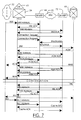
- FIG. 7 is a high level overview of the messages exchanged during call set up and release of the call schematically illustrated in FIG. 5.
- the sequence commences and ends at the PSTN 32 (FIG. 5) even though it will be understood by those skilled in the art that an unidentified switch in the PSTN 32 is actually the originator of the call and other intervening switches that are not illustrated may be involved in the call.
- an IAM generated within the PSTN 32 (not illustrated) is received by the hybrid central office 24.
- the computing module 40 of the hybrid central office responds by sending an IAM Advisory message to the IW-MSP 44 and the DA-MSP 72. Each return a IAM ACK message.
- the computing module 40 On receipt of the respective IAM ACK messages, the computing module 40 formulates and transfers a connection request to the terminating DA-MSP 72 providing the connection information described above with reference to FIG. 6. Thereafter, the computing module 40 selects an idle inter-working bridge and formulates an inter-working connection request message which it sends to the IW-MSP 44. IW-MSP 44 responds by generating an inter-working application instance as described above with reference to FIG. 5.
- the DA-MSP 72 selects an idle SVC from its SVC cache and sends a synchronized message over the SVC to the IW-MSP.
- the synchronized message identifies the call to the IW-MSP and it responds with a Synch Ack message indicating that it has identified the SVC and mapped it to the TDM end of the call. Consequently, the computing module 40 of the hybrid central office 24 forwards the IAM to the central office 68.
- the central office 68 On receipt of the IAM, the central office 68 translates the called number and verifies that the subscriber line is in-service and available. On verification, the central office 68 returns an ACM message to the hybrid central office 24.
- the computing module 40 of the hybrid central office 24 formulates and dispatches ACM Advisory messages to both the DA-MSP 72 and the IW-MSP 44. Each interface responds with a ACM ACK message. On receipt of the responses, the computing module 40 forwards the ACM message to the access tandem 30.
- the central office 68 applies ringing to the subscriber line (not illustrated) which travels back through the connection established through DA-MSP 72, ATM backbone network 22, IW-MSP 44, hybrid central office 24 and access tandem 30 to be heard by the calling party, as is well understood in the art.
- the central office 68 formulates an ANM message which it returns to the hybrid central office 24.
- the hybrid central office 24 sends ANM Advisory messages to each of the interfaces which return ANM ACK messages.
- the hybrid central office 24 On receipt of the ANM ACK messages, the hybrid central office 24 forwards the ANM message to the access tandem 30 which forwards the messages to the originating switch (not illustrated) in the PSTN and billing for the call commences.
- the release sequence for the call is substantially identical to the release sequence described above with reference to FIG. 6.
- the called party terminates the conversation by going on-hook which prompts the central office 68 to formulate and send a release message through the common channel signaling message 34 (FIG. 1 ) to the hybrid central office 24.
- the hybrid central office 24 responds by sending REL Advisory messages to each of the interfaces which return REL ACK response messages.
- the hybrid central office 24 then forwards the REL message to the access tandem 30 which forwards it through the PSTN as described above.
- the hybrid central office 40 then returns a RLC message to the central office 68 which releases all resources.
- a RLC message is also returned from access tandem 30 which prompts the computing module 40 to formulate and send RLC Advisory messages to each of the interfaces. No response to the RLC Advisory Messages is expected.
- the DA-MSP 72 who is master of the SVC cache checks cache size and determines that SVC used for the released call should be cached for future use in call set up. The DA-MSP 72 therefore adds the SVC to cache and sends a Cache SVC message to the IW-MSP 44 which responds with a Cache ACK message indicating that the terminating end of the SVC has been cached for reuse.
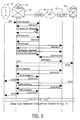
- FIG. 8 is a high-level overview of the messages exchanged during call setup and release of the call schematically illustrated in FIG. 5, wherein the call setup progresses as two separate calls, a first TDM call being setup between the IW-MSP 44 and the PSTN 32 and a second ATM call which is setup between the DA-MSP 72 and the IW-MSP 44. The two calls are bridged between the DTC 42 and the IS-MSP 44 as described above.
- an IAM generated within the PSTN 32 is received by the hybrid central office 24.
- the computing module of the hybrid central office 24 responds by sending an IAM advisory message to the IW-MSP 44.
- the IW-MSP 44 responds with an IAM ACK message.
- the computing module 40 forwards a connection request to the IW-MSP 44 providing the connection information for establishing an inter-working bridge between the DTC 42 and the IW-MSP 44 using an inter-working bridge resource as explained above.
- the IW-MSP establishes the inter-working bridge and returns an acknowledgement message (ACK). Thereafter, the computing module 40 formulates and forwards a second IAM advisory to the IW-MSP 44.
- ACK acknowledgement message
- the second IAM advisory sent to the IW-MSP 44 contains information related to the ATM leg of the call. Thereafter, the messaging sequence follows the steps described above with relation to FIG. 7 with the exception that the ISUP ACM and ANM messages are not returned to the PSTN 32 until corresponding ACM ACK and ANM ACK messages are received by the ATM leg of the call.
- the computing module 40 On receipt of the ACM ACK message, the computing module 40 forwards an ACM back to the originating switch in the PSTN 32.
- the computing module 40 forwards an ANM back to the originating switch in the PSTN 32. Both actions are shown on the lower left of FIG. 8.
- the call release sequence may also follow the steps described above with reference to FIG. 7.
- call processing was controlled by the computing module 40 of the hybrid central office 24, it should be understood that the interfaces 44, 72 and 74 may be connected to the common channel signaling network 34 and may control all call setup and call processing. In that case, the IW-MSP 44 is responsible for call processing rather than the computing module 40.
Landscapes
- Engineering & Computer Science (AREA)
- Computer Networks & Wireless Communication (AREA)
- Signal Processing (AREA)
- Telephonic Communication Services (AREA)
- Data Exchanges In Wide-Area Networks (AREA)
Applications Claiming Priority (2)
| Application Number | Priority Date | Filing Date | Title |
|---|---|---|---|
| US09/206,277 US6930998B1 (en) | 1998-12-07 | 1998-12-07 | Hybrid TDM and ATM voice switching central office and method of completing inter-office calls using same |
| US206277 | 1998-12-07 |
Publications (3)
| Publication Number | Publication Date |
|---|---|
| EP1009194A2 true EP1009194A2 (fr) | 2000-06-14 |
| EP1009194A3 EP1009194A3 (fr) | 2004-02-04 |
| EP1009194B1 EP1009194B1 (fr) | 2013-02-13 |
Family
ID=22765686
Family Applications (1)
| Application Number | Title | Priority Date | Filing Date |
|---|---|---|---|
| EP99309782A Expired - Lifetime EP1009194B1 (fr) | 1998-12-07 | 1999-12-06 | Centrale téléphonique pour voix en mode hybride ATM et TDM et procédé pour compléter des appels entre des commutateurs utilisant cette centrale |
Country Status (4)
| Country | Link |
|---|---|
| US (1) | US6930998B1 (fr) |
| EP (1) | EP1009194B1 (fr) |
| JP (1) | JP2000228681A (fr) |
| CA (1) | CA2289956C (fr) |
Families Citing this family (6)
| Publication number | Priority date | Publication date | Assignee | Title |
|---|---|---|---|---|
| US6502135B1 (en) | 1998-10-30 | 2002-12-31 | Science Applications International Corporation | Agile network protocol for secure communications with assured system availability |
| US7418504B2 (en) | 1998-10-30 | 2008-08-26 | Virnetx, Inc. | Agile network protocol for secure communications using secure domain names |
| US10511573B2 (en) | 1998-10-30 | 2019-12-17 | Virnetx, Inc. | Agile network protocol for secure communications using secure domain names |
| ATE492973T1 (de) | 1998-10-30 | 2011-01-15 | Virnetx Inc | Netzwerkprotokoll zur geschützten kommunikation |
| US6826616B2 (en) | 1998-10-30 | 2004-11-30 | Science Applications International Corp. | Method for establishing secure communication link between computers of virtual private network |
| US6615041B2 (en) * | 1998-11-05 | 2003-09-02 | Bellsouth Intellectual Property Corporation | Methods and systems for providing information to a home system regarding a wireless unit roaming in a visited system |
Citations (3)
| Publication number | Priority date | Publication date | Assignee | Title |
|---|---|---|---|---|
| EP0792076A2 (fr) | 1996-02-23 | 1997-08-27 | Lucent Technologies Inc. | Procédé et arrangement pour établir des connexions d'appel à un système de télécommunications avec un serveur du transport virtuel |
| EP0991294A2 (fr) | 1998-10-02 | 2000-04-05 | Nortel Networks Corporation | Procédé et dispositif pour faciliter l'établissement d'un appel dans un reseau ATM |
| US6141342A (en) | 1998-12-02 | 2000-10-31 | Nortel Networks Corporation | Apparatus and method for completing inter-switch calls using large trunk groups |
Family Cites Families (10)
| Publication number | Priority date | Publication date | Assignee | Title |
|---|---|---|---|---|
| JP2878805B2 (ja) * | 1990-08-20 | 1999-04-05 | 株式会社東芝 | Atm交換機 |
| BR9408313A (pt) | 1993-12-20 | 1997-08-05 | At & T Corp | Rede de telecomunicações processo para tranmitir sinais de comunicação periódicos multiplexados por rede de telecomunicações rede para comutar pacotes compostos rede de distribuição empacotada para distribuição e transmissão rede de distribuição para comutar sinais de modo de transferência assincrona chave de acesso para gerar sinais empacotados circuito de remapeamento de pacote composto e aparelho em sistema de comutação de telecomunicaçães ou grupamento |
| US5568475A (en) | 1994-12-21 | 1996-10-22 | Lucent Technologies Inc. | ATM network architecture employing an out-of-band signaling network |
| US5838682A (en) * | 1995-11-28 | 1998-11-17 | Bell Atlantic Network Services, Inc. | Method and apparatus for establishing communications with a remote node on a switched network based on hypertext dialing information received from a packet network |
| ATE293338T1 (de) * | 1995-12-11 | 2005-04-15 | Hewlett Packard Co | Verbindungsaufbaudurchgang für ein fernmeldesystem |
| GB2320642A (en) | 1996-12-21 | 1998-06-24 | Ibm | Distributed voice processing system |
| US6285680B1 (en) * | 1997-03-27 | 2001-09-04 | Microcom Systems, Inc. | Central site call routing apparatus and method |
| US6349096B1 (en) * | 1997-09-22 | 2002-02-19 | Integrated Telecom Express, Inc. | Configurable digital subscriber loop access and end-to-end data and analog voice connection system |
| US6363079B1 (en) * | 1997-12-31 | 2002-03-26 | At&T Corp. | Multifunction interface facility connecting wideband multiple access subscriber loops with various networks |
| US6868502B2 (en) * | 1998-10-15 | 2005-03-15 | Hewlett-Packard Development Company, L.P. | Combination analog and digital modem |
-
1998
- 1998-12-07 US US09/206,277 patent/US6930998B1/en not_active Expired - Fee Related
-
1999
- 1999-11-16 CA CA002289956A patent/CA2289956C/fr not_active Expired - Fee Related
- 1999-11-25 JP JP11333960A patent/JP2000228681A/ja active Pending
- 1999-12-06 EP EP99309782A patent/EP1009194B1/fr not_active Expired - Lifetime
Patent Citations (3)
| Publication number | Priority date | Publication date | Assignee | Title |
|---|---|---|---|---|
| EP0792076A2 (fr) | 1996-02-23 | 1997-08-27 | Lucent Technologies Inc. | Procédé et arrangement pour établir des connexions d'appel à un système de télécommunications avec un serveur du transport virtuel |
| EP0991294A2 (fr) | 1998-10-02 | 2000-04-05 | Nortel Networks Corporation | Procédé et dispositif pour faciliter l'établissement d'un appel dans un reseau ATM |
| US6141342A (en) | 1998-12-02 | 2000-10-31 | Nortel Networks Corporation | Apparatus and method for completing inter-switch calls using large trunk groups |
Also Published As
| Publication number | Publication date |
|---|---|
| US6930998B1 (en) | 2005-08-16 |
| CA2289956A1 (fr) | 2000-06-07 |
| EP1009194A3 (fr) | 2004-02-04 |
| CA2289956C (fr) | 2009-02-03 |
| EP1009194B1 (fr) | 2013-02-13 |
| JP2000228681A (ja) | 2000-08-15 |
Similar Documents
| Publication | Publication Date | Title |
|---|---|---|
| US6195714B1 (en) | System for transferring STM calls through ATM network by converting the STM calls to ATM and vice versa at the edge nodes of ATM network | |
| CA1312394C (fr) | Services de communication independants des entreprises de telecommunication | |
| AU701276B2 (en) | System for managing telecommunications | |
| US6069947A (en) | Communication system architecture and operating protocol therefor | |
| JP2002501326A (ja) | チャネルデータ形式で受信されたサービス要求を処理するための仮想搬送チャネルプラットフォーム | |
| US6061363A (en) | Communications system with load sharing communications interface | |
| EP1453257B1 (fr) | Procédé et dipositif pour l' établissement d' une connection de communication | |
| JP2002501335A (ja) | 仮想搬送チャネルプラットフォームのためのプログラム可能ゲートウェイ | |
| JP2002501327A (ja) | 仮想搬送チャネルプラットフォームのための資源管理部 | |
| US6930998B1 (en) | Hybrid TDM and ATM voice switching central office and method of completing inter-office calls using same | |
| US6757285B1 (en) | Method and apparatus for completing telephone calls between subnetworks | |
| JP2000216881A (ja) | 大きなトランク群を用いて交換局間呼を完成するための装置および方法 | |
| EP1091552A2 (fr) | Procédé et dispositif de services téléphoniques utilisant de commutateurs TDM et de réseaux de données | |
| JP4469039B2 (ja) | 音声または音声グレードのデータを転送する装置 | |
| CA2160467C (fr) | Systeme de telecommunication | |
| GB2333204A (en) | Communications system | |
| Ince et al. | ISDN Concepts and Standards |
Legal Events
| Date | Code | Title | Description |
|---|---|---|---|
| PUAI | Public reference made under article 153(3) epc to a published international application that has entered the european phase |
Free format text: ORIGINAL CODE: 0009012 |
|
| AK | Designated contracting states |
Kind code of ref document: A2 Designated state(s): AT BE CH CY DE DK ES FI FR GB GR IE IT LI LU MC NL PT SE |
|
| AX | Request for extension of the european patent |
Free format text: AL;LT;LV;MK;RO;SI |
|
| RAP1 | Party data changed (applicant data changed or rights of an application transferred) |
Owner name: NORTEL NETWORKS LIMITED |
|
| RAP1 | Party data changed (applicant data changed or rights of an application transferred) |
Owner name: NORTEL NETWORKS LIMITED |
|
| PUAL | Search report despatched |
Free format text: ORIGINAL CODE: 0009013 |
|
| AK | Designated contracting states |
Kind code of ref document: A3 Designated state(s): AT BE CH CY DE DK ES FI FR GB GR IE IT LI LU MC NL PT SE |
|
| AX | Request for extension of the european patent |
Extension state: AL LT LV MK RO SI |
|
| RIC1 | Information provided on ipc code assigned before grant |
Ipc: 7H 04Q 3/00 B Ipc: 7H 04Q 11/04 A |
|
| 17P | Request for examination filed |
Effective date: 20040804 |
|
| AKX | Designation fees paid |
Designated state(s): DE FR GB SE |
|
| 17Q | First examination report despatched |
Effective date: 20050623 |
|
| GRAP | Despatch of communication of intention to grant a patent |
Free format text: ORIGINAL CODE: EPIDOSNIGR1 |
|
| GRAS | Grant fee paid |
Free format text: ORIGINAL CODE: EPIDOSNIGR3 |
|
| GRAP | Despatch of communication of intention to grant a patent |
Free format text: ORIGINAL CODE: EPIDOSNIGR1 |
|
| GRAA | (expected) grant |
Free format text: ORIGINAL CODE: 0009210 |
|
| RIN1 | Information on inventor provided before grant (corrected) |
Inventor name: SYLVAIN, DANY Inventor name: LAKHANI, FAIZEL |
|
| AK | Designated contracting states |
Kind code of ref document: B1 Designated state(s): DE FR GB SE |
|
| REG | Reference to a national code |
Ref country code: GB Ref legal event code: FG4D |
|
| REG | Reference to a national code |
Ref country code: DE Ref legal event code: R096 Ref document number: 69944614 Country of ref document: DE Effective date: 20130411 |
|
| PG25 | Lapsed in a contracting state [announced via postgrant information from national office to epo] |
Ref country code: SE Free format text: LAPSE BECAUSE OF FAILURE TO SUBMIT A TRANSLATION OF THE DESCRIPTION OR TO PAY THE FEE WITHIN THE PRESCRIBED TIME-LIMIT Effective date: 20130213 |
|
| PLBE | No opposition filed within time limit |
Free format text: ORIGINAL CODE: 0009261 |
|
| STAA | Information on the status of an ep patent application or granted ep patent |
Free format text: STATUS: NO OPPOSITION FILED WITHIN TIME LIMIT |
|
| 26N | No opposition filed |
Effective date: 20131114 |
|
| REG | Reference to a national code |
Ref country code: DE Ref legal event code: R097 Ref document number: 69944614 Country of ref document: DE Effective date: 20131114 |
|
| PGFP | Annual fee paid to national office [announced via postgrant information from national office to epo] |
Ref country code: GB Payment date: 20141124 Year of fee payment: 16 |
|
| PGFP | Annual fee paid to national office [announced via postgrant information from national office to epo] |
Ref country code: FR Payment date: 20141124 Year of fee payment: 16 |
|
| PGFP | Annual fee paid to national office [announced via postgrant information from national office to epo] |
Ref country code: DE Payment date: 20141222 Year of fee payment: 16 |
|
| REG | Reference to a national code |
Ref country code: DE Ref legal event code: R119 Ref document number: 69944614 Country of ref document: DE |
|
| GBPC | Gb: european patent ceased through non-payment of renewal fee |
Effective date: 20151206 |
|
| REG | Reference to a national code |
Ref country code: FR Ref legal event code: ST Effective date: 20160831 |
|
| PG25 | Lapsed in a contracting state [announced via postgrant information from national office to epo] |
Ref country code: DE Free format text: LAPSE BECAUSE OF NON-PAYMENT OF DUE FEES Effective date: 20160701 Ref country code: GB Free format text: LAPSE BECAUSE OF NON-PAYMENT OF DUE FEES Effective date: 20151206 |
|
| PG25 | Lapsed in a contracting state [announced via postgrant information from national office to epo] |
Ref country code: FR Free format text: LAPSE BECAUSE OF NON-PAYMENT OF DUE FEES Effective date: 20151231 |