EP0992294A2 - Dispositif et procédé pour laver des barres - Google Patents
Dispositif et procédé pour laver des barres Download PDFInfo
- Publication number
- EP0992294A2 EP0992294A2 EP99119163A EP99119163A EP0992294A2 EP 0992294 A2 EP0992294 A2 EP 0992294A2 EP 99119163 A EP99119163 A EP 99119163A EP 99119163 A EP99119163 A EP 99119163A EP 0992294 A2 EP0992294 A2 EP 0992294A2
- Authority
- EP
- European Patent Office
- Prior art keywords
- gas
- frame
- liquid
- mindestens
- rod element
- Prior art date
- Legal status (The legal status is an assumption and is not a legal conclusion. Google has not performed a legal analysis and makes no representation as to the accuracy of the status listed.)
- Granted
Links
Images


Classifications
-
- B—PERFORMING OPERATIONS; TRANSPORTING
- B08—CLEANING
- B08B—CLEANING IN GENERAL; PREVENTION OF FOULING IN GENERAL
- B08B3/00—Cleaning by methods involving the use or presence of liquid or steam
- B08B3/02—Cleaning by the force of jets or sprays
- B08B3/022—Cleaning travelling work
-
- G—PHYSICS
- G21—NUCLEAR PHYSICS; NUCLEAR ENGINEERING
- G21C—NUCLEAR REACTORS
- G21C17/00—Monitoring; Testing ; Maintaining
- G21C17/06—Devices or arrangements for monitoring or testing fuel or fuel elements outside the reactor core, e.g. for burn-up, for contamination
-
- B—PERFORMING OPERATIONS; TRANSPORTING
- B08—CLEANING
- B08B—CLEANING IN GENERAL; PREVENTION OF FOULING IN GENERAL
- B08B2203/00—Details of cleaning machines or methods involving the use or presence of liquid or steam
- B08B2203/02—Details of machines or methods for cleaning by the force of jets or sprays
- B08B2203/0229—Suction chambers for aspirating the sprayed liquid
-
- Y—GENERAL TAGGING OF NEW TECHNOLOGICAL DEVELOPMENTS; GENERAL TAGGING OF CROSS-SECTIONAL TECHNOLOGIES SPANNING OVER SEVERAL SECTIONS OF THE IPC; TECHNICAL SUBJECTS COVERED BY FORMER USPC CROSS-REFERENCE ART COLLECTIONS [XRACs] AND DIGESTS
- Y02—TECHNOLOGIES OR APPLICATIONS FOR MITIGATION OR ADAPTATION AGAINST CLIMATE CHANGE
- Y02E—REDUCTION OF GREENHOUSE GAS [GHG] EMISSIONS, RELATED TO ENERGY GENERATION, TRANSMISSION OR DISTRIBUTION
- Y02E30/00—Energy generation of nuclear origin
- Y02E30/30—Nuclear fission reactors
Definitions
- the present invention relates to a device and a method for flushing of rod elements, in particular for cleaning fuel elements for Avoiding the uncontrolled detachment of those on the surface of the cladding tubes contaminants adhering to fuel assemblies during transport of the fuel assemblies, for example, from the reactor pressure vessel to those provided accordingly Fuel assembly storage racks.
- the spent fuel elements are removed from the reactor and temporarily stored in a fuel element store before further processing.
- the impurities adhering to the surface of the cladding tubes of fuel elements dissolve, which in power plant terminology are considered to be
- This effect of detachment is amplified when the fuel elements are transported under water from the reactor pressure vessel to the fuel assembly storage racks or from the fuel assembly storage racks to the transport containers.
- the previously flooded container is discharged into the unloading part of the tank
- the 4-5 meter long fuel elements are removed from the container with the help of underwater gripping tools, inserted in cans and brought into the storage racks with a crane.
- the water serves as a shield and at the same time ensures excellent visibility during unloading On the other hand, however, due to its flow movement, it also promotes, as mentioned, the detachment effect of the crud from the fuel elements, as a result of which the fuel element storage pool is contaminated.
- an object of the present invention is to avoid the uncontrolled detachment of the crud, a device and a corresponding To provide methods by means of which the fuel elements are lifted out cleaned from the storage rack or the rack in the reactor pressure vessel can be.
- the rod element can have any shape and cross section exhibit.
- the frame may then have to be adapted to this shape become.
- the frame can consist of one or more parts that can be connected to one another or also separated from one another.
- the first and the second peripheral portion of the frame are freely selected portions of the Scope of the frame. With a rectangular frame, a peripheral portion correspond approximately to one side of the rectangle, the peripheral section can but also from two, in particular adjacent sides or from Assemble parts of several sides of the rectangle.
- the suction opening in the second peripheral portion of the frame can be in an opening with any Cross section exist, which is connected to a suction device, so that Liquid or gas can be sucked off.
- the suction is carried out by a suction device separate from or connected to the frame, about a suction pump.
- the liquid used for washing or the corresponding one Gas is then removed via the discharge line.
- An underwater suction device is recommended, which is connected to the suction openings becomes.
- the liquid or gas used for the purging can be removed from the surroundings of the frame, so that the washing effect exclusively through the suction effect of the suction openings is coming.
- the water of the Fuel element or storage pool used as flushing liquid In the case of nuclear power plants, the water of the Fuel element or storage pool used as flushing liquid.
- the frame has at least the first peripheral section at least one outflow opening for the at least a liquid and / or the at least one gas. Owns at the same time the device a supply line for the at least one liquid and / or the at least one gas to the at least one outflow opening of the frame. It there is thus the possibility of the at least one liquid and / or the at least one a gas under essentially freely selectable pressure, which can only be produced by the Conditions of the device is predetermined by the supply line to the at least to conduct an outlet opening and the at least one liquid and / or the at least one gas thereby on the at least one rod element to let meet. In the context of the invention, a high pressure is regularly for the effectiveness of the flushing advantageous.
- the rinsing substance can be freely selected within certain limits is not limited to the medium currently in the area, for example Air or water. Since the rinsing substance is sucked off again, substances can also be used that are not or not in large quantities in the environment should arrive or which are recovered for economic reasons should be.
- the flushing serves primarily as described above Surface cleaning of the fuel elements. It is used for rinsing or basin Make-up water used.
- An underwater vacuum cleaner is preferably used for suction used.
- the frame completely surrounds the rod element, so that a complete flushing of the at least one rod element is guaranteed.
- Preferably is used for washing around the at least one rod element for cleaning the surface of the same, which is expedient for reasons of effectiveness by flushing the bar element as completely as possible with the minimum a liquid and / or with which at least one gas is reached.
- On completely enclosing the frame does not mean that the frame must consist of one part or of firmly connected parts. It is sufficient if there are no larger gaps between the frame parts, so that no relevant part of the bar element is untreated, i.e. from make-up water remains unaffected.
- At least one sealing element is arranged on the upper side and / or lower side of the frame in such a way that a sealing with respect to the rod element takes place.
- the frame has a rectangular shape, where two adjacent sides of the rectangle each have at least one Outflow opening and the other two sides each have at least one suction opening exhibit.
- This diagonal arrangement of the discharge openings is relative to the suction openings allows simultaneous processing, in particular the simultaneous cleaning of the rod element from two sides.
- the device can also be used turn and wash around the rod element in successive steps. It is also possible to hold the frame while the rod element is moving through the frame continuously or at certain intervals turn and thus clean the rod element from all sides.
- the entirety of the derivatives has one larger cross section than the total of the supply lines. This ensures that with the help of the suction opening and the derivations at least the liquid and / or gas volume can be absorbed or suctioned off can, which is fed through the feed lines, plus that after the rinsing in the at least one liquid and / or the at least one gas contained or dissolved contaminant particles from the surface of the at least one bar element is washed away by the washing around. There will be a continuous flow between the outlets and maintain the suction openings without congestion of the supplied liquid or the supplied gas due to insufficient suction capacity.
- the frame has at least a device for generating ultrasonic vibrations. So that will the liquid rinsing the at least one rod element in addition to theirs Movement in the direction of one of the suction openings due to the outgoing from these Suction effect also put in a kind of vibration state. This in turn brings about a better cleaning effect of those washing around the rod element Liquid and / or gas. In addition, the ultrasonic vibrations cause also immediately easier removal of contaminant particles from the rod element surface.
- the constant supply to and the simultaneous suction of liquid and / or Gas from the at least one rod element causes a constant flow of the rod element with the corresponding liquid and / or gas.
- the in turn has the consequence that there is between the surface of the rod element and the liquid flowing around them and / or the gas to frictional effects comes due to what contamination particles on the rod element surface detached and entrained with the flowing liquid and / or the gas can be.
- the actual cleaning effect is based on this.
- suction of liquid and / or gas will continue to be used together with the corresponding Liquid and / or the corresponding gas from the rod element surface loosened contaminant particles are sucked off, which also means renewed attachment to the surface of the bar element is largely prevented becomes.
- the at least one liquid and / or the at least one gas are supplied to outflow openings which are arranged on at least a first peripheral section of the frame.
- the at least one liquid and / or the at least one gas is preferably introduced at a pressure between 3 bar and 150 bar, preferably between 10 bar and 30 bar, so that the at least one liquid and / or the at least one gas with a larger one Impulse that hits at least one bar element.
- Even the bare Sweeping "of the liquid and / or the gas on the surface of the rod element is associated with increased friction and thus with a greater detachment effect of contaminant particles located on the rod surface, ie the cleaning effect is greater than at lower pressure.
- the inventive method described and / or the inventive method Device are preferably used for cleaning fuel elements of nuclear power plants used.
- the cause lies of contamination in the reactor pool of a nuclear power plant and in the fuel assembly storage pool for the most part on the surface of the cladding tubes of contaminants adhering to fuel elements, the crud. After leaving the system and reducing the temperature, the crud detaches from the Surface. This detachment effect occurs when the fuel elements are transported mostly under water between the reactor pressure vessel and the fuel assembly storage racks or the fuel assembly storage rack and the transport containers reinforced.
- the fuel assemblies are in a hanging position using a loading machine or other gripping device moved in the water.
- the pool water flows through the cladding tubes.
- the fuel assemblies are in a vertical orientation during the Removal passed through the frame of the device according to the invention and cleaned in the process.
- a one-stage diagonal rinse is preferably carried out for cleaning.
- the device according to the invention preferably has one rectangular frame on this frame is a leading from top to bottom, lateral supply line arranged, which in turn preferably with branches to nozzle-shaped, mutually adjacent outflow openings in the Frame is provided. These outflow openings are preferably at two adjacent ones Sides of the rectangular frame are provided. On the remaining, two opposite sides of the rectangular frame the totality of the derivatives, which is similar to the totality the supply lines, but with a much larger cross-section.
- the process described is also without feed water applicable.
- the surrounding medium e.g. the pool water, is then simply used.
- the single-stage according to the invention Diagonal flushing by adding a second stage in the opposite direction improved.
- the first frame becomes the same bundle as it is lifted out vertically from the storage rack or the rack in the reactor pressure vessel guided a second frame, here then the outflow and the Suction openings are arranged so that one of the resulting in the first frame diagonal flow gives opposite diagonal flow.
- the two are still going through the first frame edited pages, i.e. cleaned. It is a two-stage diagonal flush.
- the two are reinforced aforementioned diagonal rinsing devices for generating ultrasonic vibrations, so-called ultrasonic transducers. These are arranged on the frame according to the invention. Through this ultrasonic transducer the liquid is put into a vibrating state, causing the cleaning effect is reinforced.
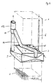
- an inventive device 1 for rinsing is at least a rod element with at least one liquid and / or a gas.
- the device 1 shown here is used in particular to clean a Bundle of fuel elements 2 during its removal from a reactor pressure vessel or from a storage rack.
- the frame 3 of the device according to the invention forms a rectangular opening 4 through which the bundle of fuel assemblies 2 is passed.
- Two contiguous insides of the illustrated Frame 3 each extend over the entire side length narrow, slit-like openings, which serve as outflow openings 5.
- the Supply line 6 runs vertically from top to bottom. In their upper section it has a branch point 7.
- part of the introduced Liquid continues vertically down to the first of the two outlets 5 passed and the other part of the liquid introduced into a branch 8 redirected to the second of the two outflow openings 5.
- the two remaining opposite adjacent insides of the Frames 3 also each have an opening that acts as suction openings 9 serve.
- the cross section of the suction openings 9 is larger than that of the outflow openings 5.
- a drain 10 leads away from the suction openings 9.
- the two derivatives 10 shown here run in a connecting piece 11 to a total derivative enlarged in cross section relative to the individual derivatives 10 12 together. This leads vertically upwards.
- the bundle of Fuel elements 2 are passed through the frame 3 in a vertical orientation.
- another device 1 according to the invention for rinsing is at least a rod element with at least one liquid and / or one gas shown in perspective.
- the device 1 shown here also serves specifically the cleaning of a bundle of fuel elements 2 during its expansion the reactor pressure vessel or from a storage rack.
- the device 1 a rectangular frame 3 through which a bundle of fuel assemblies 2 can be passed in a vertical orientation.
- the derivatives 10, the total derivative 12 and the suction openings 9 themselves do not differ from those in Figure 1, both the supply line 6 and the outflow openings 5 are configured differently than is shown in FIG. 1.
- the feed line 6 has a comparatively small cross section. Also owns it does not have a branch in its upper section. It leads directly vertically down to a first side of the rectangular frame 3.
- FIG. 3 shows another device 1 for rinsing according to the invention at least one rod element with at least one liquid and / or a gas.
- the device 1 shown here also serves specifically cleaning a bundle of fuel assemblies 2 during this Removal from the reactor pressure vessel or from a storage rack.
- the one shown here Device 1 is a combination of that in FIG. 1 and that in FIG. 2 shown devices. The totality of the derivatives is analogous to that in Figure 1 and Figure 2 shown.
- the device 1 shown here also has a rectangular frame 3, but has two different types of leads, that can be used optionally.
- the feed line 6 is similar to that in Figure 1 designed and allows operation under low pressure.
- the corresponding Outflow openings 5 are, like in FIG. 1, slit-like openings extending along the entire side.
- the other, optionally for The available supply line 6 ' is comparable to that of FIG. 2 in cross section tiny.
- the associated nozzle-shaped outflow openings 5 ' are also significantly smaller in cross section than the outflow openings 5.
- the combination of the two embodiments from FIGS. 1 and 2 makes one flexible working method possible. Depending on the degree of contamination of the fuel assemblies 2 you can work under low or high pressure.
- the present invention thus provides an apparatus and a method for Flushing, in particular for cleaning rod elements, such as nuclear fuel elements that allow quick and easy treatment on site.
Landscapes
- Physics & Mathematics (AREA)
- Engineering & Computer Science (AREA)
- Plasma & Fusion (AREA)
- General Engineering & Computer Science (AREA)
- High Energy & Nuclear Physics (AREA)
- Cleaning By Liquid Or Steam (AREA)
- Cleaning In General (AREA)
- Physical Or Chemical Processes And Apparatus (AREA)
- Electrical Discharge Machining, Electrochemical Machining, And Combined Machining (AREA)
Applications Claiming Priority (2)
| Application Number | Priority Date | Filing Date | Title |
|---|---|---|---|
| DE19846591 | 1998-10-09 | ||
| DE19846591A DE19846591C2 (de) | 1998-10-09 | 1998-10-09 | Verfahren zur Umspülung von Stabelementen und Verwendung des Verfahrens zur Reinigung von Brennelementen |
Publications (3)
| Publication Number | Publication Date |
|---|---|
| EP0992294A2 true EP0992294A2 (fr) | 2000-04-12 |
| EP0992294A3 EP0992294A3 (fr) | 2002-04-10 |
| EP0992294B1 EP0992294B1 (fr) | 2005-03-09 |
Family
ID=7883957
Family Applications (1)
| Application Number | Title | Priority Date | Filing Date |
|---|---|---|---|
| EP99119163A Expired - Lifetime EP0992294B1 (fr) | 1998-10-09 | 1999-10-06 | Dispositif et procédé pour laver des éléments combustibles |
Country Status (6)
| Country | Link |
|---|---|
| US (1) | US6231682B1 (fr) |
| EP (1) | EP0992294B1 (fr) |
| JP (1) | JP2000155192A (fr) |
| AT (1) | ATE290437T1 (fr) |
| DE (2) | DE19846591C2 (fr) |
| ES (1) | ES2239821T3 (fr) |
Cited By (1)
| Publication number | Priority date | Publication date | Assignee | Title |
|---|---|---|---|---|
| EP2616192A4 (fr) * | 2008-01-14 | 2014-05-14 | David J Gross | Nettoyage de combustible à haute densité de puissance avec transducteurs plans |
Families Citing this family (6)
| Publication number | Priority date | Publication date | Assignee | Title |
|---|---|---|---|---|
| US20080137795A1 (en) * | 2006-10-20 | 2008-06-12 | Electric Power Research Institute, Inc. | Method and apparatus for removing corrosion products from a nuclear reactor |
| SE534409C2 (sv) * | 2009-10-01 | 2011-08-09 | Westinghouse Electric Sweden | Apparat och metod för rengöring av ett nukleärt bränsleelement |
| CN101789273B (zh) * | 2010-01-22 | 2012-02-08 | 清华大学 | 一种球床高温堆燃料目视装置 |
| DE102011050633B4 (de) * | 2011-05-26 | 2017-02-23 | Siempelkamp NIS Ingenieurgesellschaft mbH | Verfahren und Anordnung zum Entfernen von Partikeln aus einer Flüssigkeit |
| FR3015758A1 (fr) | 2013-12-23 | 2015-06-26 | Commissariat Energie Atomique | Procede et dispositif de nettoyage d'un assemblage de crayons de combustible nucleaire |
| CN108648846B (zh) * | 2018-05-22 | 2020-06-05 | 广东核电合营有限公司 | 一种用于乏燃料水池扩容的水上洗吹装置及水上洗吹方法 |
Family Cites Families (22)
| Publication number | Priority date | Publication date | Assignee | Title |
|---|---|---|---|---|
| DE2034087A1 (de) * | 1970-07-09 | 1972-01-13 | Kraftwerk Union Ag | Brennelement-Lagerbecken für Kernkraftwerke |
| DE2258727A1 (de) * | 1972-11-30 | 1974-06-06 | Siemens Ag | Verfahren fuer das zonenweise umsetzen von kernreaktorbrennelementen |
| US4171002A (en) * | 1977-10-20 | 1979-10-16 | British Nuclear Fuels Ltd. | Nuclear fuel transportation containers |
| US4298015A (en) * | 1979-12-12 | 1981-11-03 | Garza Antonio M | Dishwasher |
| JPS56137300A (en) * | 1980-03-31 | 1981-10-27 | Tokyo Shibaura Electric Co | Device for removing clad of fkuel assembly |
| JPS5763300U (fr) * | 1980-10-02 | 1982-04-15 | ||
| JPS5790200A (en) | 1980-11-26 | 1982-06-04 | Tokyo Shibaura Electric Co | Method and device for removing water scale |
| US4591390A (en) * | 1981-03-25 | 1986-05-27 | Shell Internationale Research Maatschappij B. V. | Cable cleaning system |
| US4621952A (en) * | 1981-07-28 | 1986-11-11 | Union Carbide Corporation | Fluidized bed discharge process |
| DE3230520A1 (de) * | 1982-08-17 | 1984-02-23 | Abfluß-Service Inhaber Helmut Roel, 4300 Essen | Vorrichtung zum reinigen radioaktiv kontaminierter flaechen von lagerbecken, behaeltern und dergleichen |
| JPS5941800U (ja) * | 1982-09-10 | 1984-03-17 | 株式会社東芝 | 核燃料洗浄装置 |
| US4705575A (en) * | 1985-03-12 | 1987-11-10 | Kernforschungsanlage Julich Gesellschaft Mit Beschrankter Haftung | Process and arrangement for separating ceramic nuclear fuels from metallic casing or support members |
| DE3617739C2 (de) * | 1986-05-27 | 1996-05-30 | Keld Gabelgaard | Filtervorrichtung, insbesondere Unterwasser-Filtervorrichtung und Filtrierverfahren |
| JPS63167300U (fr) * | 1987-04-22 | 1988-10-31 | ||
| US5092355A (en) * | 1988-12-15 | 1992-03-03 | Westinghouse Electric Corp. | Pressure pulse method for removing debris from nuclear fuel assemblies |
| US5002079A (en) * | 1988-12-15 | 1991-03-26 | Westinghouse Electric Corp. | Pressure pulse method and system for removing debris from nuclear fuel assemblies |
| JPH04324400A (ja) * | 1991-04-24 | 1992-11-13 | Toshiba Corp | 燃料集合体の洗浄方法及びその装置 |
| DE4129362A1 (de) * | 1991-09-04 | 1992-05-14 | Ulrich Nestler | Anordnung und verfahren einer autonomen brennelement-spueleinrichtung |
| FR2682524B1 (fr) * | 1991-10-10 | 1993-12-10 | Matieres Nucleaires Cie Gle | Procede de conditionnement ou de recyclage de cartouches ioniques usagers. |
| JP3293928B2 (ja) * | 1993-02-22 | 2002-06-17 | 株式会社東芝 | 超音波洗浄方法およびその装置 |
| JPH09203796A (ja) * | 1996-01-26 | 1997-08-05 | Ishikawajima Harima Heavy Ind Co Ltd | 放射性汚染物除去装置 |
| JPH09236692A (ja) * | 1996-02-29 | 1997-09-09 | Ishikawajima Harima Heavy Ind Co Ltd | ガラス固化体表面除染装置 |
-
1998
- 1998-10-09 DE DE19846591A patent/DE19846591C2/de not_active Expired - Fee Related
-
1999
- 1999-10-06 ES ES99119163T patent/ES2239821T3/es not_active Expired - Lifetime
- 1999-10-06 EP EP99119163A patent/EP0992294B1/fr not_active Expired - Lifetime
- 1999-10-06 DE DE59911724T patent/DE59911724D1/de not_active Expired - Lifetime
- 1999-10-06 AT AT99119163T patent/ATE290437T1/de active
- 1999-10-08 US US09/415,407 patent/US6231682B1/en not_active Expired - Lifetime
- 1999-10-12 JP JP11289485A patent/JP2000155192A/ja active Pending
Cited By (1)
| Publication number | Priority date | Publication date | Assignee | Title |
|---|---|---|---|---|
| EP2616192A4 (fr) * | 2008-01-14 | 2014-05-14 | David J Gross | Nettoyage de combustible à haute densité de puissance avec transducteurs plans |
Also Published As
| Publication number | Publication date |
|---|---|
| ES2239821T3 (es) | 2005-10-01 |
| DE59911724D1 (de) | 2005-04-14 |
| US6231682B1 (en) | 2001-05-15 |
| DE19846591A1 (de) | 2000-04-20 |
| JP2000155192A (ja) | 2000-06-06 |
| ATE290437T1 (de) | 2005-03-15 |
| EP0992294B1 (fr) | 2005-03-09 |
| DE19846591C2 (de) | 2001-06-13 |
| EP0992294A3 (fr) | 2002-04-10 |
Similar Documents
| Publication | Publication Date | Title |
|---|---|---|
| DE102015106725B4 (de) | Verfahren zur maschinellen Reinigung von Werkstücken und/oder Maschinenbauteilen sowie Reinigungsanlage | |
| DE69108689T2 (de) | Vorrichtung zum Reinigen von Siliciumscheiben. | |
| DE102015116196B3 (de) | Wasch- und/oder Reinigungsanlage | |
| EP0654294A2 (fr) | Procédé et dispositif de filtration de particules solides de liquides et le rinçage du filtre à contre-courant | |
| DE3625862C2 (de) | Verfahren und Vorrichtung zur Oberflächenbehandlung von Wärmetauscherrohren | |
| EP0992294B1 (fr) | Dispositif et procédé pour laver des éléments combustibles | |
| EP0289875A1 (fr) | Méthode et dispositif pour le nettoyage des pièces à usiner | |
| WO2018069342A1 (fr) | Dispositif et procédé pour nettoyer une pièce | |
| DE19629436A1 (de) | Absaugdüse um flüssige oder staubförmige Rückständen von langgestreckten Bauteilen abzusaugen | |
| DE19709860A1 (de) | Verfahren und Vorrichtung zur Aufbereitung von Kühlschmierstoffen für Werkzeugmaschinen oder dgl. | |
| DE3531697C2 (fr) | ||
| EP2896342A1 (fr) | Réglette de répartition | |
| EP4603199A1 (fr) | Installation de lavage de roues | |
| DE102020108761A1 (de) | Verfahren und Vorrichtung zur Reinigung von 3D-gedruckten Bauteilen | |
| DE102009054962A1 (de) | Vorrichtung und Verfahren zur Aufbereitung einer Kühl- und Spülflüssigkeit | |
| DE2758550C2 (de) | Verfahren zur Entfernung von Restmengen einer Behandlungsflüssigkeit von Gegenständen und Vorrichtung zur Durchführung des Verfahrens | |
| DE3344163C2 (fr) | ||
| DE102006039035A1 (de) | Verfahren zur Oberflächenbehandlung eines Werkstückes in der Behandlungskammer einer industriellen Reinigungsanlage | |
| EP3249095A1 (fr) | Appareil de lavage et procédé de purification d'une salle blanche | |
| DE102020205232A1 (de) | Abfallflüssigkeit-behandlungsvorrichtung | |
| DE9315408U1 (de) | Vorrichtung zum Reinigen der Hohlstruktur von Werkstücken | |
| DE2543297C3 (de) | Verfahren zur Säuberung der Membranoberflächn einer Membrantrennvorrichtung | |
| DE3136186A1 (de) | Verfahren und vorrichtung zur reinigung der innenwaende von metallischen leitungssystemen durch elektropolieren mit hilfe bewegter elektroden | |
| DE2123983C3 (de) | Vorichtung zum Reinigen von unerwünchte Verunreinigungen tragenden Festkörperteilchen und Verfahren dazu | |
| DE102015104571A1 (de) | Koksofenreinigungsvorrichtung, Ofenbedienungsmaschine sowie Verfahren zur Reinigung von Koksofentüren oder Koksofentürrahmen |
Legal Events
| Date | Code | Title | Description |
|---|---|---|---|
| PUAI | Public reference made under article 153(3) epc to a published international application that has entered the european phase |
Free format text: ORIGINAL CODE: 0009012 |
|
| AK | Designated contracting states |
Kind code of ref document: A2 Designated state(s): AT BE CH CY DE DK ES FI FR GB GR IE IT LI LU MC NL PT SE |
|
| AX | Request for extension of the european patent |
Free format text: AL;LT;LV;MK;RO;SI |
|
| PUAL | Search report despatched |
Free format text: ORIGINAL CODE: 0009013 |
|
| AK | Designated contracting states |
Kind code of ref document: A3 Designated state(s): AT BE CH CY DE DK ES FI FR GB GR IE IT LI LU MC NL PT SE |
|
| AX | Request for extension of the european patent |
Free format text: AL;LT;LV;MK;RO;SI |
|
| 17P | Request for examination filed |
Effective date: 20021010 |
|
| AKX | Designation fees paid |
Free format text: AT BE CH CY DE DK ES FI FR GB GR IE IT LI LU MC NL PT SE |
|
| 17Q | First examination report despatched |
Effective date: 20040304 |
|
| GRAP | Despatch of communication of intention to grant a patent |
Free format text: ORIGINAL CODE: EPIDOSNIGR1 |
|
| RTI1 | Title (correction) |
Free format text: DEVICE AND METHOD FOR WASHING FUEL ELEMENTS |
|
| GRAS | Grant fee paid |
Free format text: ORIGINAL CODE: EPIDOSNIGR3 |
|
| GRAA | (expected) grant |
Free format text: ORIGINAL CODE: 0009210 |
|
| AK | Designated contracting states |
Kind code of ref document: B1 Designated state(s): AT BE CH CY DE DK ES FI FR GB GR IE IT LI LU MC NL PT SE |
|
| PG25 | Lapsed in a contracting state [announced via postgrant information from national office to epo] |
Ref country code: IT Free format text: LAPSE BECAUSE OF FAILURE TO SUBMIT A TRANSLATION OF THE DESCRIPTION OR TO PAY THE FEE WITHIN THE PRE;WARNING: LAPSES OF ITALIAN PATENTS WITH EFFECTIVE DATE BEFORE 2007 MAY HAVE OCCURRED AT ANY TIME BEFORE 2007. THE CORRECT EFFECTIVE DATE MAY BE DIFFERENT FROM THE ONE RECORDED.SCRIBED TIME-LIMIT Effective date: 20050309 Ref country code: IE Free format text: LAPSE BECAUSE OF FAILURE TO SUBMIT A TRANSLATION OF THE DESCRIPTION OR TO PAY THE FEE WITHIN THE PRESCRIBED TIME-LIMIT Effective date: 20050309 |
|
| REG | Reference to a national code |
Ref country code: GB Ref legal event code: FG4D Free format text: NOT ENGLISH |
|
| REG | Reference to a national code |
Ref country code: CH Ref legal event code: EP |
|
| REG | Reference to a national code |
Ref country code: IE Ref legal event code: FG4D Free format text: GERMAN |
|
| REF | Corresponds to: |
Ref document number: 59911724 Country of ref document: DE Date of ref document: 20050414 Kind code of ref document: P |
|
| PG25 | Lapsed in a contracting state [announced via postgrant information from national office to epo] |
Ref country code: GR Free format text: LAPSE BECAUSE OF FAILURE TO SUBMIT A TRANSLATION OF THE DESCRIPTION OR TO PAY THE FEE WITHIN THE PRESCRIBED TIME-LIMIT Effective date: 20050609 Ref country code: DK Free format text: LAPSE BECAUSE OF FAILURE TO SUBMIT A TRANSLATION OF THE DESCRIPTION OR TO PAY THE FEE WITHIN THE PRESCRIBED TIME-LIMIT Effective date: 20050609 |
|
| REG | Reference to a national code |
Ref country code: SE Ref legal event code: TRGR |
|
| GBT | Gb: translation of ep patent filed (gb section 77(6)(a)/1977) |
Effective date: 20050616 |
|
| REG | Reference to a national code |
Ref country code: CH Ref legal event code: NV Representative=s name: HEPP, WENGER & RYFFEL AG |
|
| PG25 | Lapsed in a contracting state [announced via postgrant information from national office to epo] |
Ref country code: PT Free format text: LAPSE BECAUSE OF FAILURE TO SUBMIT A TRANSLATION OF THE DESCRIPTION OR TO PAY THE FEE WITHIN THE PRESCRIBED TIME-LIMIT Effective date: 20050907 |
|
| REG | Reference to a national code |
Ref country code: ES Ref legal event code: FG2A Ref document number: 2239821 Country of ref document: ES Kind code of ref document: T3 |
|
| PG25 | Lapsed in a contracting state [announced via postgrant information from national office to epo] |
Ref country code: CY Free format text: LAPSE BECAUSE OF FAILURE TO SUBMIT A TRANSLATION OF THE DESCRIPTION OR TO PAY THE FEE WITHIN THE PRESCRIBED TIME-LIMIT Effective date: 20051006 |
|
| REG | Reference to a national code |
Ref country code: IE Ref legal event code: FD4D |
|
| PG25 | Lapsed in a contracting state [announced via postgrant information from national office to epo] |
Ref country code: MC Free format text: LAPSE BECAUSE OF NON-PAYMENT OF DUE FEES Effective date: 20051031 Ref country code: LU Free format text: LAPSE BECAUSE OF NON-PAYMENT OF DUE FEES Effective date: 20051031 |
|
| PLBE | No opposition filed within time limit |
Free format text: ORIGINAL CODE: 0009261 |
|
| STAA | Information on the status of an ep patent application or granted ep patent |
Free format text: STATUS: NO OPPOSITION FILED WITHIN TIME LIMIT |
|
| 26N | No opposition filed |
Effective date: 20051212 |
|
| ET | Fr: translation filed | ||
| REG | Reference to a national code |
Ref country code: FR Ref legal event code: PLFP Year of fee payment: 17 |
|
| REG | Reference to a national code |
Ref country code: FR Ref legal event code: PLFP Year of fee payment: 18 |
|
| PGFP | Annual fee paid to national office [announced via postgrant information from national office to epo] |
Ref country code: GB Payment date: 20161025 Year of fee payment: 18 Ref country code: DE Payment date: 20161028 Year of fee payment: 18 Ref country code: FI Payment date: 20161024 Year of fee payment: 18 Ref country code: NL Payment date: 20161025 Year of fee payment: 18 Ref country code: FR Payment date: 20161025 Year of fee payment: 18 Ref country code: CH Payment date: 20161025 Year of fee payment: 18 |
|
| PGFP | Annual fee paid to national office [announced via postgrant information from national office to epo] |
Ref country code: AT Payment date: 20161024 Year of fee payment: 18 Ref country code: SE Payment date: 20161025 Year of fee payment: 18 Ref country code: ES Payment date: 20161025 Year of fee payment: 18 Ref country code: BE Payment date: 20161025 Year of fee payment: 18 |
|
| REG | Reference to a national code |
Ref country code: DE Ref legal event code: R119 Ref document number: 59911724 Country of ref document: DE |
|
| REG | Reference to a national code |
Ref country code: SE Ref legal event code: EUG |
|
| REG | Reference to a national code |
Ref country code: CH Ref legal event code: PL |
|
| REG | Reference to a national code |
Ref country code: NL Ref legal event code: MM Effective date: 20171101 |
|
| REG | Reference to a national code |
Ref country code: AT Ref legal event code: MM01 Ref document number: 290437 Country of ref document: AT Kind code of ref document: T Effective date: 20171006 |
|
| GBPC | Gb: european patent ceased through non-payment of renewal fee |
Effective date: 20171006 |
|
| REG | Reference to a national code |
Ref country code: FR Ref legal event code: ST Effective date: 20180629 |
|
| PG25 | Lapsed in a contracting state [announced via postgrant information from national office to epo] |
Ref country code: CH Free format text: LAPSE BECAUSE OF NON-PAYMENT OF DUE FEES Effective date: 20171031 Ref country code: LI Free format text: LAPSE BECAUSE OF NON-PAYMENT OF DUE FEES Effective date: 20171031 Ref country code: FI Free format text: LAPSE BECAUSE OF NON-PAYMENT OF DUE FEES Effective date: 20171006 Ref country code: GB Free format text: LAPSE BECAUSE OF NON-PAYMENT OF DUE FEES Effective date: 20171006 Ref country code: DE Free format text: LAPSE BECAUSE OF NON-PAYMENT OF DUE FEES Effective date: 20180501 Ref country code: NL Free format text: LAPSE BECAUSE OF NON-PAYMENT OF DUE FEES Effective date: 20171101 |
|
| REG | Reference to a national code |
Ref country code: BE Ref legal event code: MM Effective date: 20171031 |
|
| PG25 | Lapsed in a contracting state [announced via postgrant information from national office to epo] |
Ref country code: SE Free format text: LAPSE BECAUSE OF NON-PAYMENT OF DUE FEES Effective date: 20171007 Ref country code: AT Free format text: LAPSE BECAUSE OF NON-PAYMENT OF DUE FEES Effective date: 20171006 Ref country code: BE Free format text: LAPSE BECAUSE OF NON-PAYMENT OF DUE FEES Effective date: 20171031 Ref country code: FR Free format text: LAPSE BECAUSE OF NON-PAYMENT OF DUE FEES Effective date: 20171031 |
|
| REG | Reference to a national code |
Ref country code: ES Ref legal event code: FD2A Effective date: 20181220 |
|
| PG25 | Lapsed in a contracting state [announced via postgrant information from national office to epo] |
Ref country code: ES Free format text: LAPSE BECAUSE OF NON-PAYMENT OF DUE FEES Effective date: 20171007 |