EP0992632B1 - Dispositif pour recouvrir un raccord mural - Google Patents
Dispositif pour recouvrir un raccord mural Download PDFInfo
- Publication number
- EP0992632B1 EP0992632B1 EP99119298A EP99119298A EP0992632B1 EP 0992632 B1 EP0992632 B1 EP 0992632B1 EP 99119298 A EP99119298 A EP 99119298A EP 99119298 A EP99119298 A EP 99119298A EP 0992632 B1 EP0992632 B1 EP 0992632B1
- Authority
- EP
- European Patent Office
- Prior art keywords
- rosette
- wall connection
- wall
- sleeve element
- seal carrier
- Prior art date
- Legal status (The legal status is an assumption and is not a legal conclusion. Google has not performed a legal analysis and makes no representation as to the accuracy of the status listed.)
- Expired - Lifetime
Links
- 238000009428 plumbing Methods 0.000 claims 3
- 230000000007 visual effect Effects 0.000 claims 1
- 238000011161 development Methods 0.000 description 4
- 230000018109 developmental process Effects 0.000 description 4
- 210000002105 tongue Anatomy 0.000 description 4
- 230000004323 axial length Effects 0.000 description 3
- XLYOFNOQVPJJNP-UHFFFAOYSA-N water Substances O XLYOFNOQVPJJNP-UHFFFAOYSA-N 0.000 description 3
- 239000000463 material Substances 0.000 description 2
- 239000000969 carrier Substances 0.000 description 1
- 230000001419 dependent effect Effects 0.000 description 1
- 238000006073 displacement reaction Methods 0.000 description 1
- 238000009434 installation Methods 0.000 description 1
- 230000013011 mating Effects 0.000 description 1
- 230000035515 penetration Effects 0.000 description 1
- 238000007789 sealing Methods 0.000 description 1
- 239000007921 spray Substances 0.000 description 1
Images


Classifications
-
- E—FIXED CONSTRUCTIONS
- E03—WATER SUPPLY; SEWERAGE
- E03C—DOMESTIC PLUMBING INSTALLATIONS FOR FRESH WATER OR WASTE WATER; SINKS
- E03C1/00—Domestic plumbing installations for fresh water or waste water; Sinks
- E03C1/02—Plumbing installations for fresh water
- E03C1/04—Water-basin installations specially adapted to wash-basins or baths
- E03C1/042—Arrangements on taps for wash-basins or baths for connecting to the wall
-
- E—FIXED CONSTRUCTIONS
- E03—WATER SUPPLY; SEWERAGE
- E03C—DOMESTIC PLUMBING INSTALLATIONS FOR FRESH WATER OR WASTE WATER; SINKS
- E03C1/00—Domestic plumbing installations for fresh water or waste water; Sinks
- E03C1/02—Plumbing installations for fresh water
- E03C1/021—Devices for positioning or connecting of water supply lines
-
- E—FIXED CONSTRUCTIONS
- E03—WATER SUPPLY; SEWERAGE
- E03C—DOMESTIC PLUMBING INSTALLATIONS FOR FRESH WATER OR WASTE WATER; SINKS
- E03C1/00—Domestic plumbing installations for fresh water or waste water; Sinks
- E03C1/02—Plumbing installations for fresh water
- E03C1/04—Water-basin installations specially adapted to wash-basins or baths
- E03C1/0403—Connecting the supply lines to the tap body
-
- E—FIXED CONSTRUCTIONS
- E03—WATER SUPPLY; SEWERAGE
- E03C—DOMESTIC PLUMBING INSTALLATIONS FOR FRESH WATER OR WASTE WATER; SINKS
- E03C2201/00—Details, devices or methods not otherwise provided for
- E03C2201/50—Constructional features of escutcheons for domestic plumbing installations
Definitions
- Rosettes are known for covering wall connections to which sanitary fittings are connected. These have the task to cover the actual wall connection, namely a protruding from the wall pipe socket, and its surroundings. At the same time they should allow access to the fastening device with which the sanitary fitting is attached to the wall connection.
- the invention has for its object to provide a means for covering a wall connection, which allows a simple structure with a cover while simultaneous access to the connection point.
- the invention proposes a device with the features of claim 1. Further developments of the invention are the subject matter of the dependent claims, the wording of which as well as the wording of the abstract is incorporated by reference into the content of the description.
- the seal carrier can be made of cheaper-looking material, as it is covered by the rosette.
- Access to the fastener is made possible by moving the sleeve member axially into its one end position where it allows access. After complete assembly, it is then moved to the second position, where it covers the fastening device optically. It can be provided that the sleeve element can still be moved so far in arranged in its final position seal carrier that the fastening device is accessible. This means that one only needs to move the sleeve member to approach the fastener without altering the seal carrier and / or the rosette.
- the seal carrier can be fastened to the wall connection.
- the attachment may be, for example, a screw.
- the seal carrier in particular serve the existing on the wall connection anyway thread.
- seal carrier can be snapped on the wall connection.
- this is meant that it locks itself with the help of resilient or deformable parts or elements at certain points of the wall connection.
- the attachment of the seal carrier to the wall connection can be made either directly or via an intermediate element, in particular the sleeve element.
- the rosette can be set, for example, in development of the invention to the seal carrier. This can for example, also be done by snapping, in particular snapping around the edge of the seal carrier. This attachment may be sufficient because the rosette can be made of a lightweight and thin material. It can also be provided on the seal carrier snap devices.
- the rosette can be attached to the wall connection, either directly or with the interposition of the sleeve element. All other common types of fastening are also possible.
- Another way of fixing the rosette may be that it is supported on the sanitary element, in particular by means of the sleeve member.
- the aforementioned mobility at least in the axial direction can be achieved, for example, in that the sleeve element is displaceably guided on the seal carrier and / or the rosette.
- corresponding bearing surfaces can be provided.
- the sleeve member is connected via a screw with the seal carrier and / or with the rosette.
- the axial mobility is caused by a rotation.
- the sleeve member is bolted to the wall connection.
- the existing thread of the wall connection can be used.
- the sleeve member connected to a part of the fastening device, in particular screwed is, for example, with a union nut, with which the valve is fixed to the thread of the wall connection.
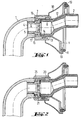
- Fig. 1 shows a section through a broken off part of a sanitary fitting, which is screwed by means of a union nut to a wall connection.
- This wall connection is covered by a covering device, which is shown on both sides of the axis of the connection in two axially different positions.
- the sanitary fitting 1 is shown only partially. It is a part of a mixing valve, which has a so-called S-connection 2 to be connected to a house installation.
- the fitting 1 contains in the end face 3 a threaded opening 4 into which a threaded piece 5 is screwed.
- the threaded piece 5 includes a passage 6.
- a union nut 7 is attached, which is screwed with its internal thread on the external thread of the connecting piece 8 of the terminal.
- a flat gasket is inserted between the end face of the threaded piece 5 and the end face of the nozzle 8, a flat gasket is inserted.
- the connection 8 comes from a wall surface, which is provided for example with tiles. The environment of the connection 8 and the connection 8 itself should be shielded from view.
- the seal carrier 9 On the external thread of the nozzle 8 of the wall connection a seal carrier 9 is screwed.
- the seal carrier 9 includes a circumferential ring 10 having a groove disposed in its associated surface of the wall, into which a sealing ring 11 is inserted.
- the seal carrier 9 In its region arranged within the ring 10, the seal carrier 9 has the shape of a truncated cone 12, in the middle of which a short threaded area 13 is formed.
- a guide portion 14 At the threaded portion with which it engages in the external thread of the connecting piece 8, a guide portion 14 connects to its free end, which has a radial distance from the external thread. The radial distance is chosen so that the union nut 7 can be screwed into this space.
- a sleeve member 15 On the outside of the guide portion 14, a sleeve member 15 is pushed, which is thereby guided on the guide portion 14.
- the inner diameter of the cylindrical sleeve member 15 corresponds to the outer diameter of the cylindrical guide portion 14 of the seal carrier 9.
- the sleeve member has in the region of its the valve. 1 associated end 16 an end wall with an opening 17.
- the sleeve element 15 can be displaced in the direction of the seal carrier 9 or the wall until the inside of the end wall bears against the end of the guide section 14. In this position, a fitter can attack on the union nut 7, for example, unscrew the valve. The assembly is in the opposite direction in front of him.
- a rosette 18 is snapped, which shields the seal carrier 9 against view.
- the rosette 18 has in the region of its side facing away from the wall on a central opening which is dimensioned so that the sleeve member 15 just fits into this opening.
- the assembly for example, as follows.
- the provided with the seal 11 seal carrier 9 is screwed onto the socket 8 until it rests against the wall.
- the sleeve element 15 is pushed onto it, namely so far in the direction of the wall associated side until the inside of the end face abuts the guide portion 14.
- the rosette is pushed over the sleeve member 15 and connected in the edge region with the seal carrier 9.
- the radial outer side of the ring 10 extends slightly undercut, so that the edge 19 of the rosette 18 remains held there.
- the seal carrier contains snap devices that can hold the rosette.
- the fitting 1 is approximated to the connection and the union nut screwed onto the socket 8.
- the sleeve element will be switched off the rosette 18 pulled out until it comes to the fitting 1 to the plant.
- the fit between the sleeve member 15 and the guide portion 14 can be designed so that the sleeve member then remains in this position.
- Fig. 2 differs from Fig. 1 only slightly, so that a detailed description of the entire device is not repeated.
- the free end facing away from the wall of the seal carrier 9 is formed as a smooth guide portion 14, it is formed in the embodiment of FIG. 2 as also provided with a radial distance threaded portion 20.
- This threaded portion 20 includes an external thread which engages in an internal thread 21 of the sleeve member 25.
- the internal thread 21 extends over the entire axial length of the sleeve member 25. Instead of a displacement as in the embodiment of Fig. 1 so the sleeve member is rotated. This pre-rotation leads due to the thread at the same time to a movement in the axial direction.
- the seal carrier 29 includes in its central region a projection 30 in the form of a short cylinder, which is bounded by an inwardly directed flange 31 at its front. On the inside of the cylindrical projection 30, an internal thread 32 is formed.
- the sleeve element 35 engages with an end flange 36 through the opening of the central projection 30 of the seal carrier 29 and with an external thread 37 in the internal thread 32 a. Characterized the sleeve member 35 is adjustably guided on the seal carrier 29 by a screw.
- the sleeve member 35 includes on its inside a ring 38 which engages in the external thread of the nozzle 8.
- the sleeve element is thus adjustable over the wall connection via a thread.
- both the seal carrier can be screwed with the screwed rosette 18 relative to the sleeve member, as well as the sleeve member 35 relative to the nozzle 8 of the wall connection. It is therefore also possible in this embodiment, after assembly, to remove the rosette carrier from the wall.
- the ring 38 may also be formed without a thread, so that it is supported on the union nut.
- the seal carrier 49 is thereby fixed to the wall connection, that at its ring 10 a plurality of approximately tapered resilient tongues 50 are formed. These tongues 50 are supported by their free end on a shoulder 40 of the nozzle 8. By the S-shaped configuration of the tongues 50, a sufficient force is thereby generated to press the ring 10 with the seal 11 against the wall surface.
- the rosette 48 starting from its end facing away from the wall 41, starting inside a skirt 42 which surrounds the opening of the rosette 48 coaxially.
- the skirt 42 is provided with an internal thread 43.
- the sleeve member 45 engages with an end flange 46 a.
- the sleeve member 45 can be adjusted relative to the rosette in a similar manner by screwing, as was the case with the embodiment of FIG. 3 relative to the seal carrier 29.
- the end flange 47 facing away from the end 47 of the sleeve member 45 is formed as a pipe end, ie without an end wall as in the embodiment of FIG. 1.
- this end 47 is supported on a mating surface of the valve 1 from. It is therefore possible that the rosette 48 and sleeve member 45 existing unit between the valve and the wall is supported and thus determines. A connection between the sleeve member 45 and the wall connection is no longer necessary.
- a shoulder 51 is formed which forms an annular surface parallel to the wall surface. With this shoulder 51, the rosette 48 engages the front of the ring 10. In the aforementioned screw connection between the fitting 1 and the wall, the rosette 48 presses the ring 10 against the wall surface.
- the resilient tongues 50 serve here for support and possibly also for centering. But they can also be omitted.
- the seal carrier 49 is constructed in the same manner as in Fig. 4, while the rosette 18 corresponds to the rosette of the embodiment of FIG.
- the sleeve member 55 includes an over its entire axial length extending internal thread, with which it is screwed onto an external thread 56 of the union nut 57.
- the external thread 56 of the union nut 57 is arranged in the wall-facing end region of the union nut 57. The assembly of this arrangement is done in a similar manner as in the other embodiments.
- the seal carrier is provided with channels around its circumference, at which point this water can emerge again. This leaves the critical wall area within the seal 11 dry.
- FIG. 5 a shows a single view in the direction of the arrow V in FIG. 5.
- Individual flexible latching devices in the form of teeth 58 are integrally formed on the seal carriers, which engage in corresponding recesses of the rosette 18 and fix them by latching.
- these locking projections 58 do not form on the rosette carrier, but on the rosette, and provide for the rosette support depressions, recesses or even a corresponding circumferential shoulder.
Landscapes
- Health & Medical Sciences (AREA)
- Life Sciences & Earth Sciences (AREA)
- Engineering & Computer Science (AREA)
- Hydrology & Water Resources (AREA)
- Public Health (AREA)
- Water Supply & Treatment (AREA)
- Connector Housings Or Holding Contact Members (AREA)
- Domestic Plumbing Installations (AREA)
- Valve Housings (AREA)
- Cable Accessories (AREA)
- Closures For Containers (AREA)
- Mechanical Coupling Of Light Guides (AREA)
Claims (13)
- Dispositif pour recouvrir un raccord mural pour une robinetterie sanitaire (1), comprenant1.1 un porte-joint (9, 29, 49) qui,1.1.1 sur son côté tourné vers le mur, présente un logement pour un joint (11),1.2 une rosette (18, 48) qui1.2.1 est destinée au recouvrement visuel du porte-joint (9, 29, 49), ainsi qu'1.3 un élément de douille (15, 25, 35, 45, 55) qui1.3.1 est maintenu de manière déplaçable en direction axiale par rapport au raccord mural et1.3.2 est destiné au recouvrement d'un dispositif de fixation entre la robinetterie sanitaire (1) et le raccord mural,
caractérisé en ce que la rosette est exécutée comme composant distinct du porte joint. - Dispositif selon la revendication 1, dans lequel l'élément de douille (15, 25, 35, 45, 55) peut être poussé jusqu'à ce que le dispositif de fixation devienne accessible.
- Dispositif selon la revendication 1 ou 2, dans lequel le porte-joint (9, 29, 49) peut être fixé sur le raccord mural.
- Dispositif selon l'une quelconque des revendications précédentes, dans lequel le porte-joint (9, 29) peut être vissé sur le raccord mural.
- Dispositif selon l'une quelconque des revendications précédentes, dans lequel le porte-joint (49) peut être encliqueté sur le raccord mural.
- Dispositif selon l'une quelconque des revendications précédentes, dans lequel le porte-joint (29) peut être fixé sur le raccord mural à l'aide de l'élément de douille (35).
- Dispositif selon l'une quelconque des revendications précédentes, dans lequel la rosette (18, 48) peut être fixée sur le porte-joint (9, 29, 49), de préférence par encliquetage sur la partie de bord de celui-ci.
- Dispositif selon l'une quelconque des revendications précédentes, dans lequel la rosette (18, 48) peut être fixée sur le raccord mural, en particulier à l'aide de l'élément de douille (35).
- Dispositif selon l'une quelconque des revendications précédentes, dans lequel la rosette (18) s'appuie sur la robinetterie sanitaire (1), en particulier à l'aide de l'élément de douille (45).
- Dispositif selon l'une quelconque des revendications précédentes, dans lequel l'élément de douille (15, 25, 35, 45, 55) est mené de manière coulissante sur le porte-joint et/ou la rosette (18, 48).
- Dispositif selon l'une quelconque des revendications précédentes, dans lequel l'élément de douille peut être vissé avec le porte-joint et/ou avec la rosette.
- Dispositif selon l'une quelconque des revendications précédentes, dans lequel l'élément de douille peut être vissé avec le raccord mural.
- Dispositif selon l'une quelconque des revendications précédentes, dans lequel l'élément de douille peut être vissé avec une partie du dispositif de fixation.
Applications Claiming Priority (2)
| Application Number | Priority Date | Filing Date | Title |
|---|---|---|---|
| DE19846779 | 1998-10-10 | ||
| DE19846779A DE19846779A1 (de) | 1998-10-10 | 1998-10-10 | Einrichtung zum Abdecken eines Wandanschlusses |
Publications (3)
| Publication Number | Publication Date |
|---|---|
| EP0992632A2 EP0992632A2 (fr) | 2000-04-12 |
| EP0992632A3 EP0992632A3 (fr) | 2001-01-17 |
| EP0992632B1 true EP0992632B1 (fr) | 2006-08-23 |
Family
ID=7884069
Family Applications (1)
| Application Number | Title | Priority Date | Filing Date |
|---|---|---|---|
| EP99119298A Expired - Lifetime EP0992632B1 (fr) | 1998-10-10 | 1999-09-29 | Dispositif pour recouvrir un raccord mural |
Country Status (5)
| Country | Link |
|---|---|
| EP (1) | EP0992632B1 (fr) |
| AT (1) | ATE337441T1 (fr) |
| DE (2) | DE19846779A1 (fr) |
| ES (1) | ES2272028T3 (fr) |
| PT (1) | PT992632E (fr) |
Families Citing this family (4)
| Publication number | Priority date | Publication date | Assignee | Title |
|---|---|---|---|---|
| DE102014010130A1 (de) * | 2014-07-09 | 2016-01-14 | Grohe Ag | Abdeckvorrichtung für ein Anschlussstück einer Wasserarmatur |
| DE202015100038U1 (de) * | 2015-01-07 | 2015-02-19 | Frank Bernhard | S-Anschluss zur Verbindung einer Wasserleitung mit einer Armatur |
| DE102021207445A1 (de) | 2021-07-13 | 2023-01-19 | Hansgrohe Se | Sanitärarmatur-Wandanschlusseinrichtung und wandmontierbare Sanitärarmatur |
| DE102024109037A1 (de) * | 2024-03-28 | 2025-10-02 | Grohe Ag | Adapter zum Verbinden einer Sanitärarmatur mit einem S-Anschluss, Sanitärinstallation mit einem solchen Adapter, Verwendung eines Adapters sowie Verfahren zur Befestigung einer Sanitärarmatur |
Family Cites Families (8)
| Publication number | Priority date | Publication date | Assignee | Title |
|---|---|---|---|---|
| DE879678C (de) * | 1951-09-22 | 1953-06-15 | Hansa Metallwerke Ag | Wandrosette zum Abdecken der Rohranschlussstelle von Auslaufventilen |
| US3939865A (en) * | 1974-05-13 | 1976-02-24 | Zin-Plas Corporation | Diverter spout valve mechanism |
| DE7523305U (de) * | 1975-07-22 | 1975-11-20 | Bast S | Rosette zum abdecken des anschlusses von leitungen insbesondere von mischbatterien |
| DE3907893A1 (de) * | 1989-03-10 | 1990-09-13 | Grohe Armaturen Friedrich | Mischbatterie |
| DE4034898C2 (de) * | 1990-11-02 | 1994-03-17 | Ideal Standard | Abdeckrosette für sanitäre Wasserarmaturen, insbesondere für Unterputzarmaturen |
| DE4134511A1 (de) * | 1991-10-18 | 1993-04-22 | Grohe Armaturen Friedrich | Rosette fuer einen wandanschluss einer mischbatterie |
| US5257645A (en) * | 1993-02-16 | 1993-11-02 | Moen Incorporated | Concealed faucet handle mounting |
| DE19702356A1 (de) * | 1997-01-23 | 1998-07-30 | Grohe Kg Hans | Sanitärarmatur mit einer Rosette |
-
1998
- 1998-10-10 DE DE19846779A patent/DE19846779A1/de not_active Withdrawn
-
1999
- 1999-09-29 ES ES99119298T patent/ES2272028T3/es not_active Expired - Lifetime
- 1999-09-29 PT PT99119298T patent/PT992632E/pt unknown
- 1999-09-29 DE DE59913791T patent/DE59913791D1/de not_active Expired - Lifetime
- 1999-09-29 EP EP99119298A patent/EP0992632B1/fr not_active Expired - Lifetime
- 1999-09-29 AT AT99119298T patent/ATE337441T1/de not_active IP Right Cessation
Also Published As
| Publication number | Publication date |
|---|---|
| DE19846779A1 (de) | 2000-04-13 |
| EP0992632A2 (fr) | 2000-04-12 |
| EP0992632A3 (fr) | 2001-01-17 |
| ES2272028T3 (es) | 2007-04-16 |
| DE59913791D1 (de) | 2006-10-05 |
| ATE337441T1 (de) | 2006-09-15 |
| PT992632E (pt) | 2006-12-29 |
Similar Documents
| Publication | Publication Date | Title |
|---|---|---|
| EP1261824B1 (fr) | Robinet sanitaire, en particulier mitigeur menager | |
| DE3843095C2 (de) | Befestigungseinrichtung für Verkleidungen | |
| EP2000681B1 (fr) | Manchon support | |
| DE4430114C2 (de) | Anschlußstück für einen Kunststoffschlauch einer Badezimmer-Handbrause | |
| DE60205641T2 (de) | Zur verbindung zweier röhrenförmiger elemente verwendete kupplung und montageverfahren dafür | |
| DE2816450C2 (de) | Befestigungsvorrichtung für elektrische Geräte, beispielsweise Steuerschalter | |
| EP2778298B1 (fr) | Système de raccordement de robinetteries sanitaires | |
| DE60115413T2 (de) | Fitting für eine druckmittelkupplung für kunststoffrohre | |
| EP0992632B1 (fr) | Dispositif pour recouvrir un raccord mural | |
| DE19853950B4 (de) | Abdeck-Rosette | |
| DE102005001303A1 (de) | Sanitäres Verteilerventil | |
| EP0499886B1 (fr) | Robinetterie murale sanitaire | |
| DE19501313A1 (de) | Seitenbrause | |
| EP2687640B1 (fr) | Mitigeur sanitaire mural | |
| DE102008032238A1 (de) | Halterung | |
| EP0762037A1 (fr) | Raccord vissé pour tuyaux | |
| EP1649111A1 (fr) | Dispositif de retenue pour une douche | |
| EP4303371B1 (fr) | Robinetterie sanitaire pourvue d'élément de verrouillage | |
| EP0786614A1 (fr) | Vanne sanitaire | |
| DE19955261A1 (de) | Ventil, insbesondere Thermostatventil für Heizungsanlagen | |
| DE29724014U1 (de) | Montage-Baugruppe | |
| DE19507716C1 (de) | Schallentkoppelte Befestigung einer Rohrmuffe oder dergleichen | |
| EP0786613B1 (fr) | Fixation d'un levier de commande à une vanne sanitaire | |
| DE3830201A1 (de) | Sanitaerarmatur | |
| DE102019119531A1 (de) | Verbindungselement für eine Schlauchleitung |
Legal Events
| Date | Code | Title | Description |
|---|---|---|---|
| PUAI | Public reference made under article 153(3) epc to a published international application that has entered the european phase |
Free format text: ORIGINAL CODE: 0009012 |
|
| AK | Designated contracting states |
Kind code of ref document: A2 Designated state(s): AT BE CH CY DE DK ES FI FR GB GR IE IT LI LU MC NL PT SE |
|
| AX | Request for extension of the european patent |
Free format text: AL;LT;LV;MK;RO;SI |
|
| PUAL | Search report despatched |
Free format text: ORIGINAL CODE: 0009013 |
|
| AK | Designated contracting states |
Kind code of ref document: A3 Designated state(s): AT BE CH CY DE DK ES FI FR GB GR IE IT LI LU MC NL PT SE |
|
| AX | Request for extension of the european patent |
Free format text: AL;LT;LV;MK;RO;SI |
|
| 17P | Request for examination filed |
Effective date: 20010420 |
|
| AKX | Designation fees paid |
Free format text: AT BE CH CY DE DK ES FI FR GB GR IE IT LI LU MC NL PT SE |
|
| AXX | Extension fees paid |
Free format text: SI PAYMENT 20010420 |
|
| 17Q | First examination report despatched |
Effective date: 20021114 |
|
| GRAP | Despatch of communication of intention to grant a patent |
Free format text: ORIGINAL CODE: EPIDOSNIGR1 |
|
| GRAS | Grant fee paid |
Free format text: ORIGINAL CODE: EPIDOSNIGR3 |
|
| GRAA | (expected) grant |
Free format text: ORIGINAL CODE: 0009210 |
|
| AK | Designated contracting states |
Kind code of ref document: B1 Designated state(s): AT BE CH CY DE DK ES FI FR GB GR IE IT LI LU MC NL PT SE |
|
| AX | Request for extension of the european patent |
Extension state: SI |
|
| PG25 | Lapsed in a contracting state [announced via postgrant information from national office to epo] |
Ref country code: NL Free format text: LAPSE BECAUSE OF FAILURE TO SUBMIT A TRANSLATION OF THE DESCRIPTION OR TO PAY THE FEE WITHIN THE PRESCRIBED TIME-LIMIT Effective date: 20060823 Ref country code: IE Free format text: LAPSE BECAUSE OF FAILURE TO SUBMIT A TRANSLATION OF THE DESCRIPTION OR TO PAY THE FEE WITHIN THE PRESCRIBED TIME-LIMIT Effective date: 20060823 Ref country code: FI Free format text: LAPSE BECAUSE OF FAILURE TO SUBMIT A TRANSLATION OF THE DESCRIPTION OR TO PAY THE FEE WITHIN THE PRESCRIBED TIME-LIMIT Effective date: 20060823 |
|
| RAP1 | Party data changed (applicant data changed or rights of an application transferred) |
Owner name: HANSGROHE AG |
|
| REG | Reference to a national code |
Ref country code: GB Ref legal event code: FG4D Free format text: NOT ENGLISH |
|
| REG | Reference to a national code |
Ref country code: CH Ref legal event code: NV Representative=s name: TROESCH SCHEIDEGGER WERNER AG Ref country code: CH Ref legal event code: EP |
|
| REG | Reference to a national code |
Ref country code: IE Ref legal event code: FG4D Free format text: LANGUAGE OF EP DOCUMENT: GERMAN |
|
| PG25 | Lapsed in a contracting state [announced via postgrant information from national office to epo] |
Ref country code: MC Free format text: LAPSE BECAUSE OF NON-PAYMENT OF DUE FEES Effective date: 20060930 Ref country code: BE Free format text: LAPSE BECAUSE OF NON-PAYMENT OF DUE FEES Effective date: 20060930 |
|
| REF | Corresponds to: |
Ref document number: 59913791 Country of ref document: DE Date of ref document: 20061005 Kind code of ref document: P |
|
| GBT | Gb: translation of ep patent filed (gb section 77(6)(a)/1977) |
Effective date: 20061004 |
|
| PG25 | Lapsed in a contracting state [announced via postgrant information from national office to epo] |
Ref country code: SE Free format text: LAPSE BECAUSE OF FAILURE TO SUBMIT A TRANSLATION OF THE DESCRIPTION OR TO PAY THE FEE WITHIN THE PRESCRIBED TIME-LIMIT Effective date: 20061123 Ref country code: DK Free format text: LAPSE BECAUSE OF FAILURE TO SUBMIT A TRANSLATION OF THE DESCRIPTION OR TO PAY THE FEE WITHIN THE PRESCRIBED TIME-LIMIT Effective date: 20061123 |
|
| REG | Reference to a national code |
Ref country code: PT Ref legal event code: SC4A Free format text: AVAILABILITY OF NATIONAL TRANSLATION Effective date: 20061012 |
|
| NLV1 | Nl: lapsed or annulled due to failure to fulfill the requirements of art. 29p and 29m of the patents act | ||
| REG | Reference to a national code |
Ref country code: IE Ref legal event code: FD4D |
|
| ET | Fr: translation filed | ||
| REG | Reference to a national code |
Ref country code: ES Ref legal event code: FG2A Ref document number: 2272028 Country of ref document: ES Kind code of ref document: T3 |
|
| PLBE | No opposition filed within time limit |
Free format text: ORIGINAL CODE: 0009261 |
|
| STAA | Information on the status of an ep patent application or granted ep patent |
Free format text: STATUS: NO OPPOSITION FILED WITHIN TIME LIMIT |
|
| 26N | No opposition filed |
Effective date: 20070524 |
|
| PGFP | Annual fee paid to national office [announced via postgrant information from national office to epo] |
Ref country code: ES Payment date: 20070925 Year of fee payment: 9 |
|
| PG25 | Lapsed in a contracting state [announced via postgrant information from national office to epo] |
Ref country code: AT Free format text: LAPSE BECAUSE OF NON-PAYMENT OF DUE FEES Effective date: 20060929 |
|
| PGFP | Annual fee paid to national office [announced via postgrant information from national office to epo] |
Ref country code: CH Payment date: 20070924 Year of fee payment: 9 |
|
| BERE | Be: lapsed |
Owner name: HANSGROHE A.G. Effective date: 20060930 |
|
| PGFP | Annual fee paid to national office [announced via postgrant information from national office to epo] |
Ref country code: GB Payment date: 20070921 Year of fee payment: 9 |
|
| PGFP | Annual fee paid to national office [announced via postgrant information from national office to epo] |
Ref country code: IT Payment date: 20070925 Year of fee payment: 9 |
|
| PG25 | Lapsed in a contracting state [announced via postgrant information from national office to epo] |
Ref country code: GR Free format text: LAPSE BECAUSE OF FAILURE TO SUBMIT A TRANSLATION OF THE DESCRIPTION OR TO PAY THE FEE WITHIN THE PRESCRIBED TIME-LIMIT Effective date: 20061124 |
|
| PGFP | Annual fee paid to national office [announced via postgrant information from national office to epo] |
Ref country code: FR Payment date: 20070926 Year of fee payment: 9 |
|
| PG25 | Lapsed in a contracting state [announced via postgrant information from national office to epo] |
Ref country code: LU Free format text: LAPSE BECAUSE OF NON-PAYMENT OF DUE FEES Effective date: 20060929 |
|
| PG25 | Lapsed in a contracting state [announced via postgrant information from national office to epo] |
Ref country code: CY Free format text: LAPSE BECAUSE OF FAILURE TO SUBMIT A TRANSLATION OF THE DESCRIPTION OR TO PAY THE FEE WITHIN THE PRESCRIBED TIME-LIMIT Effective date: 20060823 |
|
| REG | Reference to a national code |
Ref country code: PT Ref legal event code: MM4A Free format text: LAPSE DUE TO NON-PAYMENT OF FEES Effective date: 20090330 |
|
| REG | Reference to a national code |
Ref country code: CH Ref legal event code: PL |
|
| GBPC | Gb: european patent ceased through non-payment of renewal fee |
Effective date: 20080929 |
|
| PG25 | Lapsed in a contracting state [announced via postgrant information from national office to epo] |
Ref country code: PT Free format text: LAPSE BECAUSE OF NON-PAYMENT OF DUE FEES Effective date: 20090330 |
|
| REG | Reference to a national code |
Ref country code: FR Ref legal event code: ST Effective date: 20090529 |
|
| PG25 | Lapsed in a contracting state [announced via postgrant information from national office to epo] |
Ref country code: IT Free format text: LAPSE BECAUSE OF NON-PAYMENT OF DUE FEES Effective date: 20080929 |
|
| PG25 | Lapsed in a contracting state [announced via postgrant information from national office to epo] |
Ref country code: LI Free format text: LAPSE BECAUSE OF NON-PAYMENT OF DUE FEES Effective date: 20080930 Ref country code: FR Free format text: LAPSE BECAUSE OF NON-PAYMENT OF DUE FEES Effective date: 20080930 Ref country code: CH Free format text: LAPSE BECAUSE OF NON-PAYMENT OF DUE FEES Effective date: 20080930 |
|
| REG | Reference to a national code |
Ref country code: ES Ref legal event code: FD2A Effective date: 20080930 |
|
| PG25 | Lapsed in a contracting state [announced via postgrant information from national office to epo] |
Ref country code: GB Free format text: LAPSE BECAUSE OF NON-PAYMENT OF DUE FEES Effective date: 20080929 |
|
| PGFP | Annual fee paid to national office [announced via postgrant information from national office to epo] |
Ref country code: PT Payment date: 20070920 Year of fee payment: 9 |
|
| PG25 | Lapsed in a contracting state [announced via postgrant information from national office to epo] |
Ref country code: ES Free format text: LAPSE BECAUSE OF NON-PAYMENT OF DUE FEES Effective date: 20080930 |
|
| REG | Reference to a national code |
Ref country code: DE Ref legal event code: R082 Ref document number: 59913791 Country of ref document: DE Representative=s name: PATENTANWAELTE RUFF, WILHELM, BEIER, DAUSTER &, DE |
|
| REG | Reference to a national code |
Ref country code: DE Ref legal event code: R082 Ref document number: 59913791 Country of ref document: DE Representative=s name: PATENTANWAELTE RUFF, WILHELM, BEIER, DAUSTER &, DE Effective date: 20120910 Ref country code: DE Ref legal event code: R081 Ref document number: 59913791 Country of ref document: DE Owner name: HANSGROHE SE, DE Free format text: FORMER OWNER: HANSGROHE AG, 77761 SCHILTACH, DE Effective date: 20120910 |
|
| PGFP | Annual fee paid to national office [announced via postgrant information from national office to epo] |
Ref country code: DE Payment date: 20131009 Year of fee payment: 15 |
|
| REG | Reference to a national code |
Ref country code: DE Ref legal event code: R119 Ref document number: 59913791 Country of ref document: DE |
|
| PG25 | Lapsed in a contracting state [announced via postgrant information from national office to epo] |
Ref country code: DE Free format text: LAPSE BECAUSE OF NON-PAYMENT OF DUE FEES Effective date: 20150401 |