EP0992872A2 - Anzeigevorrichtung und Verfahren zu ihrer Herstellung - Google Patents
Anzeigevorrichtung und Verfahren zu ihrer Herstellung Download PDFInfo
- Publication number
- EP0992872A2 EP0992872A2 EP99306816A EP99306816A EP0992872A2 EP 0992872 A2 EP0992872 A2 EP 0992872A2 EP 99306816 A EP99306816 A EP 99306816A EP 99306816 A EP99306816 A EP 99306816A EP 0992872 A2 EP0992872 A2 EP 0992872A2
- Authority
- EP
- European Patent Office
- Prior art keywords
- substrate
- resistors
- shaft
- signal
- resistor
- Prior art date
- Legal status (The legal status is an assumption and is not a legal conclusion. Google has not performed a legal analysis and makes no representation as to the accuracy of the status listed.)
- Withdrawn
Links
Images




Classifications
-
- G—PHYSICS
- G05—CONTROLLING; REGULATING
- G05G—CONTROL DEVICES OR SYSTEMS INSOFAR AS CHARACTERISED BY MECHANICAL FEATURES ONLY
- G05G9/00—Manually-actuated control mechanisms provided with one single controlling member co-operating with two or more controlled members, e.g. selectively, simultaneously
- G05G9/02—Manually-actuated control mechanisms provided with one single controlling member co-operating with two or more controlled members, e.g. selectively, simultaneously the controlling member being movable in different independent ways, movement in each individual way actuating one controlled member only
- G05G9/04—Manually-actuated control mechanisms provided with one single controlling member co-operating with two or more controlled members, e.g. selectively, simultaneously the controlling member being movable in different independent ways, movement in each individual way actuating one controlled member only in which movement in two or more ways can occur simultaneously
- G05G9/047—Manually-actuated control mechanisms provided with one single controlling member co-operating with two or more controlled members, e.g. selectively, simultaneously the controlling member being movable in different independent ways, movement in each individual way actuating one controlled member only in which movement in two or more ways can occur simultaneously the controlling member being movable by hand about orthogonal axes, e.g. joysticks
-
- G—PHYSICS
- G06—COMPUTING OR CALCULATING; COUNTING
- G06F—ELECTRIC DIGITAL DATA PROCESSING
- G06F3/00—Input arrangements for transferring data to be processed into a form capable of being handled by the computer; Output arrangements for transferring data from processing unit to output unit, e.g. interface arrangements
- G06F3/01—Input arrangements or combined input and output arrangements for interaction between user and computer
- G06F3/02—Input arrangements using manually operated switches, e.g. using keyboards or dials
- G06F3/0202—Constructional details or processes of manufacture of the input device
- G06F3/021—Arrangements integrating additional peripherals in a keyboard, e.g. card or barcode reader, optical scanner
- G06F3/0213—Arrangements providing an integrated pointing device in a keyboard, e.g. trackball, mini-joystick
-
- G—PHYSICS
- G06—COMPUTING OR CALCULATING; COUNTING
- G06F—ELECTRIC DIGITAL DATA PROCESSING
- G06F3/00—Input arrangements for transferring data to be processed into a form capable of being handled by the computer; Output arrangements for transferring data from processing unit to output unit, e.g. interface arrangements
- G06F3/01—Input arrangements or combined input and output arrangements for interaction between user and computer
- G06F3/03—Arrangements for converting the position or the displacement of a member into a coded form
- G06F3/033—Pointing devices displaced or positioned by the user, e.g. mice, trackballs, pens or joysticks; Accessories therefor
- G06F3/0338—Pointing devices displaced or positioned by the user, e.g. mice, trackballs, pens or joysticks; Accessories therefor with detection of limited linear or angular displacement of an operating part of the device from a neutral position, e.g. isotonic or isometric joysticks
-
- G—PHYSICS
- G05—CONTROLLING; REGULATING
- G05G—CONTROL DEVICES OR SYSTEMS INSOFAR AS CHARACTERISED BY MECHANICAL FEATURES ONLY
- G05G9/00—Manually-actuated control mechanisms provided with one single controlling member co-operating with two or more controlled members, e.g. selectively, simultaneously
- G05G9/02—Manually-actuated control mechanisms provided with one single controlling member co-operating with two or more controlled members, e.g. selectively, simultaneously the controlling member being movable in different independent ways, movement in each individual way actuating one controlled member only
- G05G9/04—Manually-actuated control mechanisms provided with one single controlling member co-operating with two or more controlled members, e.g. selectively, simultaneously the controlling member being movable in different independent ways, movement in each individual way actuating one controlled member only in which movement in two or more ways can occur simultaneously
- G05G9/047—Manually-actuated control mechanisms provided with one single controlling member co-operating with two or more controlled members, e.g. selectively, simultaneously the controlling member being movable in different independent ways, movement in each individual way actuating one controlled member only in which movement in two or more ways can occur simultaneously the controlling member being movable by hand about orthogonal axes, e.g. joysticks
- G05G2009/0474—Manually-actuated control mechanisms provided with one single controlling member co-operating with two or more controlled members, e.g. selectively, simultaneously the controlling member being movable in different independent ways, movement in each individual way actuating one controlled member only in which movement in two or more ways can occur simultaneously the controlling member being movable by hand about orthogonal axes, e.g. joysticks characterised by means converting mechanical movement into electric signals
-
- G—PHYSICS
- G05—CONTROLLING; REGULATING
- G05G—CONTROL DEVICES OR SYSTEMS INSOFAR AS CHARACTERISED BY MECHANICAL FEATURES ONLY
- G05G9/00—Manually-actuated control mechanisms provided with one single controlling member co-operating with two or more controlled members, e.g. selectively, simultaneously
- G05G9/02—Manually-actuated control mechanisms provided with one single controlling member co-operating with two or more controlled members, e.g. selectively, simultaneously the controlling member being movable in different independent ways, movement in each individual way actuating one controlled member only
- G05G9/04—Manually-actuated control mechanisms provided with one single controlling member co-operating with two or more controlled members, e.g. selectively, simultaneously the controlling member being movable in different independent ways, movement in each individual way actuating one controlled member only in which movement in two or more ways can occur simultaneously
- G05G9/047—Manually-actuated control mechanisms provided with one single controlling member co-operating with two or more controlled members, e.g. selectively, simultaneously the controlling member being movable in different independent ways, movement in each individual way actuating one controlled member only in which movement in two or more ways can occur simultaneously the controlling member being movable by hand about orthogonal axes, e.g. joysticks
- G05G2009/0474—Manually-actuated control mechanisms provided with one single controlling member co-operating with two or more controlled members, e.g. selectively, simultaneously the controlling member being movable in different independent ways, movement in each individual way actuating one controlled member only in which movement in two or more ways can occur simultaneously the controlling member being movable by hand about orthogonal axes, e.g. joysticks characterised by means converting mechanical movement into electric signals
- G05G2009/04762—Force transducer, e.g. strain gauge
Definitions
- This invention generally relates to a pointing device for controlling the positioning, movement and operation of an electronic device, for example, a cursor on a display screen.
- an electronic device for example, a cursor on a display screen.
- the specific embodiment illustrated includes: a shaft, a substrate, resistor based strain gages, a printed circuit board and control electronics mounted on the printed circuit board.
- US-A-5894301 relates to a collar mounted pointing stick and has the same assignee as the present invention.
- EP-A-844584 relates to a pointing stick with z-axis actuation and has the same assignee as the present invention.
- EP-A-905600 relates to a unified bodied z-axis pointing stick and has the same assignee as the present invention.
- EP-A-862103 relates to a z-axis pointing stick with ESD protection and has the same assignee as the present invention.
- a small stubby, button-like joystick centrally around the keys of the computer keyboard, specifically at the juncture of the "g," “h 1 ' and “b” keys of the standard t 'QWERTY” keyboard.
- the joystick also known as a pointing stick, was sensitive to lateral pressure, the amount and direction of which were sensed and input into the computer to cause movement of the cursor, and the speed and direction of cursor movement corresponded to the amount and direction of pressure on the joystick.
- the joystick is connected by a flexible cable to a computer mother board where it connects to several electronic circuit devices that amplify and condition the signal coming form the joystick.
- the signal from the joystick is a low level analog signal.
- Electronic devices on the mother board amplify the low level analog signal and convert it to a digital signal.
- the electrical signal coming from the joystick is a low level analog signal.
- the signal travels along the flexible cable it looses some of its amplitude and is skewed due to attenuation of the signal.
- the signal can be corrupted due to coupling from external electromagnetic interference.
- an electronic device for example, a cursor on a display screen.
- a shaft there is a shaft, a substrate or printed circuit board having apertures, resistor based strain gages, and control electronics mounted on the printed circuit board.
- the printed circuit board is mounted to a keyboard base.
- the device includes a shaft having a first and second end.
- a substrate has the first end of the shaft attached.
- Several strain sensitive resistors are mounted on the substrate around the shaft for generating an electrical signal representative of a magnitude and direction of force applied to the shaft by a user.
- Several apertures are in the substrate, each aperture is located between a pair of strain sensitive resistors.
- a signal conditioning means is mounted to the substrate, and electrically connected to the resistors for conditioning the electrical signal. The signal conditioning means operates to receive the electrical signal as an input and provides a conditioned signal as an output.
- the resistors each separated by an aperture.
- a printed circuit board includes the actuator and has signal conditioning means mounted to the printed circuit board and electrically connected to the resistors for receiving the electrical signal, conditioning the electrical signal and outputing the conditioned signal.
- a substrate has the first end of the shaft attached.
- Several strain sensitive resistors are mounted on the substrate. The resistors are disposed radially around the shaft. The strain sensitive resistors are operable to generate an electrical signal representative of a magnitude and direction of force applied to the shaft by a user. Each resistor is separated by an aperture in the substrate.
- a mounting bracket contains the printed circuit board and is adapted to mounting to a keyboard base.
- It is a further feature of the invention to provide an electronic control device for allowing a user to control the movement or operation of a responsive electronic system including a substrate.
- a resistor means is mounted to the substrate to generating an analog signal representative of a direction of mechanical force applied thereon by the user.
- a signal conditioning means is mounted to the substrate, for receiving the analog signal from the resistor means as an input and generate a digital signal as an output.
- the resistor means includes either a shaft attached to the substrate and several strain sensitive resistors mounted on the substrate, each resistor separated by an aperture, the resistors and the apertures are disposed radially around the shaft or the resistor means includes a cavity disposed on a side of the substrate with a shaft extending through the cavity and attached to the substrate and strain sensitive resistors mounted to another side of the substrate, each resistor being disposed around the shaft and partially over the cavity.
- FIG. 1 is a top view of the preferred embodiment of a pointing stick having chip resistors.
- FIG. 2 is a side view of figure 1.
- FIG. 3 is a top view of an alternative embodiment of a pointing stick having chip resistors.
- FIG. 4 is a side view of figure 3.
- FIG. 5 is a cross-sectional view of the pointing stick of figure 1 mounted on a keyboard using a mounting bracket.
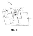
- FIG. 6 is a perspective view of a keyboard with the pointing stick.
- FIG. 7 is a view of a computer system and the pointing stick mounted on a keyboard.
- FIG. 8 is a side cross-sectional view of a discrete chip resistor of the pointing stick of figure 1.
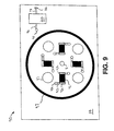
- FIG. 9 is a top view of an alternative embodiment of a pointing stick having screen printed polymer resistors.
- pointing stick assembly 10 has a stick or shaft 11 and a substrate or printed circuit board 14.
- Stick 11 can be made from ceramic, plastic or metal.
- Shaft 11 extends through a substrate bore 19.
- Shaft 11 is held in bore 19 by crimping, heat staking or by using an epoxy.
- Printed circuit board 14 has a top side 15 and a bottom side 13.
- Several strain gauge chip resistors 16 are located on top side 15. Resistors 16 could also be located on side 13.
- Chip resistors 16 are arrayed in a group of four around shaft 11.
- each of the resistors 16 is an aperture 17 which extends through printed circuit board 14.
- the apertures 17, cause the stress of flexing printed circuit board 14 by shaft 11, to be concentrated onto resistors 16.
- Electrically conductive circuit lines 18 connect between the resistors and signal conditioning circuit device 20. Shaft 11, circuit board 14, resistors 16 and apertures 17 make up actuator 12.
- the resistors 16 are typically connected in a bridge configuration by the circuit lines 18.
- Printed circuit board or substrate 14 has resistors 16 connected to circuit lines 18 by conventional electronic interconnection techniques such as soldering. Similarly, signal conditioning circuitry 20 is connected to another end of circuit line 18 by another solder joint. Terminals 22 connect with signal processing or conditioning circuit device 20 on printed circuit board 14 via circuit lines 18.
- Signal processing device 20 is a conventional pointing stick electronic signal processing device known as Trackpoint and is commercially available from Philips Electronics Semiconductor Division.
- Several terminals 22 are provided to connect from printed circuit board 14 to an external electrical circuit (not shown) such as a computer motherboard.
- Figure 8 shows details of a side cross-sectional view of discrete chip resistor 16 mounted to printed circuit board 14.
- the resistor 16 has metallic bond pads 84 on each end.
- the bond pads 84 are electrically and mechanically connected to circuit lines 18 by solder 81.
- a glue 83 is used to hold the resistor 18 to the circuit board 14.
- the glue 83 also assists in transferring the stress from movement of shaft 11 to the resistors 16.
- an encapsulating cover coat 82 can be placed over the resistor 16 to act as a protective sealant.
- cover coats such as epoxy, or silicones can be used.
- Pointing stick assembly 10 can be assembled as follows: The first step is to screen solder paste 81 onto lines 18 and dispense glue 83 onto, board 14 at the location of the resistors. Next, the resistors 16 and device 20 are placed onto printed circuit board 14 using conventional surface mount pick and place techniques. Next, the board 14 is soldered by passing the board through an IR solder reflow oven. Next, an optional cover coat 82 could be applied. The stick 11 is placed into and fastened to board 14. Finally, assembly 10 is tested.
- pointing stick assembly 30 has a cylindrical stick or shaft 11 and a planar substrate or printed circuit board 14.
- Circuit board 14 has a circular shaped cavity 24 located on bottom side 13.
- Stick 11 can be made from ceramic, plastic or metal.
- Shaft 11 extends through a substrate bore 19.
- Shaft 11 has a collar 25 at one end.
- Shaft 11 is held in bore 19 by crimping, heat staking or by using an epoxy.
- the printed circuit board 14 has a top side 15 and a bottom side 13. Several strain gauge chip resistors 16 are located on top side 15.
- the chip resistors 18 are arrayed in a group of four around shaft 11.
- the chip resistors 16 are strain gage chip resistors.
- the cavity 24 causes the stress of flexing the printed circuit board 14 by shaft 11 to be concentrated onto resistors 16.
- Electrically conductive circuit lines 18 connect between the resistors and signal conditioning circuit device 20. Shaft 11, resistors 16 and cavity 24, make up actuator 32.
- the resistor is mounted to the circuit board, the same as in figures 1 and 2.
- Printed circuit board or substrate 14 has resistors 16 connected to circuit lines 18 by conventional electronic interconnection techniques such as soldering. Similarly, signal conditioning circuitry 20 is connected to another end of circuit line 18 by another solder joint. Terminals 22 connect with signal processing or conditioning circuit device 20 on printed circuit board 14 via circuit lines 18.
- Signal processing device 20 is a conventional pointing stick electronic signal processing device known as Trackpoint and is commercially available from Philips Electronics Semiconductor Division.
- Several terminals 22 are provided to connect from printed circuit board 14 to an external electrical circuit (not shown) such as a computer motherboard.
- Pointing stick assembly 30 would be assembled the same as for assembly 10.
- Figure 5 shows a partial cross-sectional view of pointing stick assembly 10 mounted on a keyboard.
- Keyboard assembly 40 is a representation of a keyboard. Assembly 40 has a keyboard base 41, keys 42, and keyboard aperture 43.
- Pointing stick 10 is mounted to keyboard 40 with a mounting bracket 45. Shaft 11 extends through keyboard aperture 43 and between keys 42.
- Mounting bracket 45 is attached to keyboard base 41 by conventional fasteners such as rivet 44. Pointing stick assembly 10 is supported and contained by bracket 45 below the keyboard base 41.
- Figure 6 shows a keyboard base 41 with the shaft 11 extending upwardly between keys 42.
- a rubber cap 48 is shown in phantom. The cap 48 may or may not be placed over shaft 11 to improve the ergonomics or feel for the user.
- Figure 7 shows a computer system and a keyboard assembly 40 with pointing stick assembly 10.
- Pointing stick 10 is located between keys 42.
- Keyboard 40 is electrically connected to computer 212 by cable 218.
- Computer 206 is electrically connected to monitor 213 by cable 206.
- Monitor 213 has a cursor 209 on the screen.
- Pointing stick assembly 10 allows a user to control the position of cursor 209 on monitor 213.
- printed circuit board 14 contains other electronic components necessary for signal conditioning which are mounted using conventional surface mount techniques.
- the assembly 10 is placed into bracket 45 and shaft 11 is inserted through keyboard base bore 43.
- Keyboard assembly 40 is completed by attaching bracket 45 to keyboard base 41 by fasteners 44.
- Figure 9 shows an alternative embodiment of a pointing stick assembly 90 having screen printed polymer resistors.
- a stick or shaft 11 is shown mounted in a substrate or printed circuit board 14.
- the screen printed polymer resistors 91 are applied using conventional screen printing techniques to circuit board 14.
- a conductor 92 is connected on each side of resistor 91 and connects to a via connection line 93.
- the via connection line 93 is connected to a via 94 which passes through circuit board 14 and electrically connects various layers in the circuit board which contain various wiring geometries.
- Resistors 91 are arrayed in a group of four around shaft 11. Between each of the resistors 91 is an aperture 17 which extends through printed circuit board 14. The apertures 17, cause the stress of flexing printed circuit board 14 by shaft 11, to be concentrated onto resistors 91.
- the vias 94 electrically connect by a circuit line (not shown) with the vias 95 which connect to circuit line 96 which is connected to signal conditioning circuit device 20.
- Electrically conductive circuit lines 18 connect between signal conditioning circuit device 20 and terminal 22.
- Signal processing device 20 is a conventional pointing stick electronic signal processing device known as Trackpoint and is commercially available from Philips Electronics Semiconductor Division. Terminals 22 are provided to connect from printed circuit board 14 to an external electrical circuit (not shown) such as a computer motherboard.
- Seffernick forces are those forces that are applied to a supporting structure, a keyboard for example, that are translated to the pointing stick. For example, typing on a keyboard can generate seffernick forces. In that case, the pointing stick is so sensitive that a user would be activating the pointing stick operation unintentionally. The sensitive electronics on the pointing stick would sense the deformation of the keyboard support surfaces and translate that into deformation of its own support surface and mistakenly generate control signals. Thus, seffernick forces are those forces that are translated from a support structure through the body of the pointing stick and to the electronic components of the pointing stick sufficient to generate unintentional control signals.
- a metal or ceramic ring 97 is shown encircling the resistors 91 and shaft 11.
- the vias 94 are required in order to route electrical signals outside the inner circle of ring 97.
- the ring 97 could also be used in the embodiments shown in figures 1 and 3 with discrete chip resistors.
- printed circuitry board 14 be another material such as a ceramic or a flexible film. Even though only one layer of circuit lines 18 are shown, it is possible to have a multilayer circuit board, for a more compact design. It is further possible to have additional signal processing devices 20 mounted on circuit board 14 to add more circuit functions.
- Keyboard 40 is a representation of a keyboard and can be most any multilayered keyboard design.
- pointing stick assembly 10 disposed below keyboard base 41, with shaft 11 extending upwardly, it is considered equivalent to have pointing stick assembly 10 disposed on the top of the keyboard base 41 and positioned below the keys 42. Further, assembly 10 could be placed in a cutout region in base 41.
- the specification has shown the pointing stick assembly 10 mounted to a keyboard base 41, it is contemplated, however, to mount the pointing stick assembly to other types of bases or structures like remote control devices or joysticks.
- Another variation of the preferred embodiment is to use other types of fasteners to hold the control assembly 10 to the keyboard besides rivet 44 such as glue, pressfitting, a retainer with holding tabs or a separate bracket.
- circuit lines 18 could be located on the bottom surface 13. Vias or plated thru holes could be used to electrically connect circuit lines 18 to the top surface 15.
- Shaft 11 has been shown as cylindrical. However, it is contemplated that other shaped shafts could be used such as hexagonal or octagonal or square.
- apertures 17 located between resistors 16. It is contemplated to have the apertures 17 extend under resistors 16 partially or completely to enhance stress concentration. It is contemplated to have the apertures 17 shaped in other shapes than that shown, such as U shaped, or circular or square or rectangular. It is further contemplated that apertures 17 may be omitted.
Landscapes
- Engineering & Computer Science (AREA)
- General Engineering & Computer Science (AREA)
- Theoretical Computer Science (AREA)
- Physics & Mathematics (AREA)
- General Physics & Mathematics (AREA)
- Human Computer Interaction (AREA)
- Automation & Control Theory (AREA)
- Position Input By Displaying (AREA)
- Force Measurement Appropriate To Specific Purposes (AREA)
Applications Claiming Priority (2)
| Application Number | Priority Date | Filing Date | Title |
|---|---|---|---|
| US168022 | 1988-03-14 | ||
| US09/168,022 US6359613B1 (en) | 1998-10-07 | 1998-10-07 | Pointing stick having chip resistors |
Publications (2)
| Publication Number | Publication Date |
|---|---|
| EP0992872A2 true EP0992872A2 (de) | 2000-04-12 |
| EP0992872A3 EP0992872A3 (de) | 2002-04-10 |
Family
ID=22609766
Family Applications (1)
| Application Number | Title | Priority Date | Filing Date |
|---|---|---|---|
| EP19990306816 Withdrawn EP0992872A3 (de) | 1998-10-07 | 1999-08-27 | Anzeigevorrichtung und Verfahren zu ihrer Herstellung |
Country Status (4)
| Country | Link |
|---|---|
| US (2) | US6359613B1 (de) |
| EP (1) | EP0992872A3 (de) |
| JP (1) | JP2000112652A (de) |
| TW (1) | TW463118B (de) |
Cited By (1)
| Publication number | Priority date | Publication date | Assignee | Title |
|---|---|---|---|---|
| WO2013153048A1 (de) * | 2012-04-11 | 2013-10-17 | Behr-Hella Thermocontrol Gmbh | Bedieneinheit für eine fahrzeugkomponente |
Families Citing this family (57)
| Publication number | Priority date | Publication date | Assignee | Title |
|---|---|---|---|---|
| US6359613B1 (en) * | 1998-10-07 | 2002-03-19 | Cts Corporation | Pointing stick having chip resistors |
| TW430098U (en) * | 1999-05-04 | 2001-04-11 | Acer Peripherals Inc | Sensitive pointing device with ability of being miniatured |
| US7176891B2 (en) * | 2000-02-22 | 2007-02-13 | Brother Kogyo Kabushiki Kaisha | Pointing device, keyboard mounting the pointing device, and electronic device provided with the keyboard |
| US6529186B1 (en) * | 2000-10-26 | 2003-03-04 | International Business Machines Corporation | Method and system for index finger controlled pointing device positioned on home row keys |
| TW501772U (en) * | 2000-12-01 | 2002-09-01 | Darfon Electronics Corp | Point stick and notebook computer using the same |
| WO2002052236A1 (en) * | 2000-12-25 | 2002-07-04 | K-Tech Devices Corp. | Stress sensor |
| JP3902134B2 (ja) * | 2001-01-22 | 2007-04-04 | エランテック デバイシーズ コーポレイション | 応力センサ |
| JP2003004562A (ja) * | 2001-06-18 | 2003-01-08 | Alps Electric Co Ltd | 入力装置ならびに検出装置 |
| US6753850B2 (en) * | 2001-07-24 | 2004-06-22 | Cts Corporation | Low profile cursor control device |
| CN1310123C (zh) * | 2001-07-27 | 2007-04-11 | 义发科技股份有限公司 | 输入装置及其制造方法 |
| WO2003016848A1 (en) * | 2001-08-09 | 2003-02-27 | Elantech Devices Corporation | Stress sensor |
| US7254149B2 (en) | 2002-03-19 | 2007-08-07 | Finisar Corporation | Submount, pedestal, and bond wire assembly for a transistor outline package with reduced bond wire inductance |
| US7042067B2 (en) * | 2002-03-19 | 2006-05-09 | Finisar Corporation | Transmission line with integrated connection pads for circuit elements |
| US7044657B2 (en) * | 2002-03-19 | 2006-05-16 | Finisar Corporation | Transistor outline package with exteriorly mounted resistors |
| US6932518B2 (en) * | 2002-03-19 | 2005-08-23 | Finisar Corporation | Circuit board having traces with distinct transmission impedances |
| US6593536B1 (en) | 2002-05-21 | 2003-07-15 | Daimlerchrysler Corporation | Multi-axis switch with redundant contacts |
| US7033176B2 (en) | 2002-07-17 | 2006-04-25 | Powergrid Fitness, Inc. | Motion platform system and method of rotating a motion platform about plural axes |
| AU2003274939A1 (en) | 2002-08-29 | 2004-03-19 | Dept. Of Veterans Affairs | Variable compliance joystick with compensation algorithms |
| USD514627S1 (en) | 2002-12-04 | 2006-02-07 | Powergrid Fitness, Inc. | Exercise system for controlling a video game |
| US20080146336A1 (en) * | 2002-12-04 | 2008-06-19 | Philip Feldman | Exercise Gaming Device and Method of Facilitating User Exercise During Video Game Play |
| US20070155589A1 (en) * | 2002-12-04 | 2007-07-05 | Philip Feldman | Method and Apparatus for Operatively Controlling a Virtual Reality Scenario with an Isometric Exercise System |
| USD510391S1 (en) | 2002-12-04 | 2005-10-04 | Powergrid Fitness, Inc. | Exercise device for controlling a video game |
| US20060097453A1 (en) * | 2002-12-04 | 2006-05-11 | Philip Feldman | Game controller with force sensing input devices and method of measuring applied forces to game controller input devices to interact with a gaming application |
| US7727117B2 (en) * | 2002-12-04 | 2010-06-01 | Ialabs-Ca, Llc | Method and apparatus for operatively controlling a virtual reality scenario with a physically demanding interface |
| US7699755B2 (en) * | 2002-12-04 | 2010-04-20 | Ialabs-Ca, Llc | Isometric exercise system and method of facilitating user exercise during video game play |
| US20040180719A1 (en) * | 2002-12-04 | 2004-09-16 | Philip Feldman | Game controller support structure and isometric exercise system and method of facilitating user exercise during game interaction |
| US7121982B2 (en) * | 2002-12-04 | 2006-10-17 | Powergrid Fitness, Inc. | Computer interactive isometric exercise system and method for operatively interconnecting the exercise system to a computer system for use as a peripheral |
| US6937227B2 (en) * | 2003-07-14 | 2005-08-30 | Iowa State University Research Foundation, Inc. | Hand-held pointing device |
| US8350345B2 (en) | 2003-12-29 | 2013-01-08 | Vladimir Vaganov | Three-dimensional input control device |
| US9034666B2 (en) | 2003-12-29 | 2015-05-19 | Vladimir Vaganov | Method of testing of MEMS devices on a wafer level |
| US7880247B2 (en) * | 2003-12-29 | 2011-02-01 | Vladimir Vaganov | Semiconductor input control device |
| US7554167B2 (en) * | 2003-12-29 | 2009-06-30 | Vladimir Vaganov | Three-dimensional analog input control device |
| US7772657B2 (en) * | 2004-12-28 | 2010-08-10 | Vladimir Vaganov | Three-dimensional force input control device and fabrication |
| US20050264528A1 (en) * | 2004-05-26 | 2005-12-01 | Burry Stephen W | Low profile pointing device with tactile feedback |
| US20060223634A1 (en) * | 2005-04-04 | 2006-10-05 | Philip Feldman | Game controller connection system and method of selectively connecting a game controller with a plurality of different video gaming systems |
| US7331226B2 (en) * | 2005-05-20 | 2008-02-19 | Powergrid Fitness, Inc. | Force measurement system for an isometric exercise device |
| CN101454895B (zh) * | 2006-05-22 | 2012-12-19 | 弗拉多米尔·瓦格诺夫 | 半导体输入控制装置 |
| JP5427343B2 (ja) * | 2007-04-20 | 2014-02-26 | 任天堂株式会社 | ゲームコントローラ |
| JP5008188B2 (ja) * | 2007-05-31 | 2012-08-22 | ミネベア株式会社 | 3軸力センサ及び3軸力検出方法 |
| JP5133022B2 (ja) * | 2007-10-04 | 2013-01-30 | 任天堂株式会社 | プログラム、情報処理装置、情報処理システムおよび情報処理方法 |
| JP5427346B2 (ja) * | 2007-10-05 | 2014-02-26 | 任天堂株式会社 | 荷重検出プログラム、荷重検出装置、荷重検出システムおよび荷重検出方法 |
| JP5080196B2 (ja) | 2007-10-09 | 2012-11-21 | 任天堂株式会社 | プログラム、情報処理装置、情報処理システムおよび情報処理方法 |
| JP4382844B2 (ja) | 2007-10-31 | 2009-12-16 | 任天堂株式会社 | 調整用加重機、および調整用加重方法 |
| TWI368157B (en) * | 2008-03-26 | 2012-07-11 | Elan Microelectronics Corp | Stress sensor and electronic device haveing the same |
| JP5361349B2 (ja) * | 2008-11-28 | 2013-12-04 | 任天堂株式会社 | 情報処理装置、コンピュータプログラム、情報処理システム、および情報処理方法 |
| JP5806443B2 (ja) * | 2008-12-26 | 2015-11-10 | 任天堂株式会社 | 生体情報管理システム |
| JP5271121B2 (ja) * | 2009-03-09 | 2013-08-21 | 任天堂株式会社 | 情報処理プログラム、情報処理装置、情報処理システム、および情報処理方法 |
| JP5436909B2 (ja) * | 2009-03-30 | 2014-03-05 | 任天堂株式会社 | 情報処理プログラム、情報処理装置、情報処理システム、および、情報処理方法 |
| JP5456358B2 (ja) * | 2009-04-20 | 2014-03-26 | 任天堂株式会社 | 情報処理プログラムおよび情報処理装置 |
| TWI410854B (zh) * | 2009-07-01 | 2013-10-01 | Elan Microelectronics Corp | 應力感應器及其組裝方法 |
| JP5161182B2 (ja) * | 2009-09-28 | 2013-03-13 | 任天堂株式会社 | 情報処理プログラム及び情報処理装置 |
| JP5610735B2 (ja) * | 2009-09-29 | 2014-10-22 | 任天堂株式会社 | 情報処理プログラム、情報処理装置、情報処理方法、および、情報処理システム |
| JP5496591B2 (ja) | 2009-09-30 | 2014-05-21 | 任天堂株式会社 | 情報処理プログラム及び情報処理装置 |
| JP5363358B2 (ja) * | 2010-01-18 | 2013-12-11 | ミネベア株式会社 | ポインティングデバイス |
| DE102011004061A1 (de) * | 2011-02-14 | 2012-08-16 | Endress + Hauser Gmbh + Co. Kg | Elektronisches Gerät und Schutzelement hierfür für den Einsatz in explosionsgefährdeten Bereichen |
| US9593991B2 (en) | 2015-07-29 | 2017-03-14 | Apple Inc. | Printed circuits with embedded strain gauges |
| US10497094B2 (en) * | 2016-12-28 | 2019-12-03 | Nokia Technologies Oy | Method and apparatus for multi-band blending of a seam in an image derived from multiple cameras |
Citations (12)
| Publication number | Priority date | Publication date | Assignee | Title |
|---|---|---|---|---|
| US4680577A (en) | 1983-11-28 | 1987-07-14 | Tektronix, Inc. | Multipurpose cursor control keyswitch |
| US4876524A (en) | 1985-07-19 | 1989-10-24 | Jenkins Richard L | Six-axis joystick control |
| US5407285A (en) | 1990-07-24 | 1995-04-18 | Franz; Patrick J. | Pointing stick in a computer keyboard for cursor control |
| US5473347A (en) | 1994-03-16 | 1995-12-05 | Gateway 2000 | Integrated pointing and signaling device |
| US5489900A (en) | 1994-06-03 | 1996-02-06 | International Business Machines Corporation | Force sensitive transducer for use in a computer keyboard |
| US5521596A (en) | 1990-11-29 | 1996-05-28 | Lexmark International, Inc. | Analog input device located in the primary typing area of a keyboard |
| US5659334A (en) | 1993-12-15 | 1997-08-19 | Interlink Electronics, Inc. | Force-sensing pointing device |
| EP0844584A2 (de) | 1996-11-25 | 1998-05-27 | CTS Corporation | Hinweisanordnung |
| EP0862103A2 (de) | 1997-02-04 | 1998-09-02 | CTS Corporation | Anzeigevorrichtung |
| EP0905600A1 (de) | 1997-09-26 | 1999-03-31 | CTS Corporation | Steuerknüppel |
| US5894301A (en) | 1996-09-23 | 1999-04-13 | Cts Corporation | Collar mounted pointing stick |
| US8270098B2 (en) | 2008-02-20 | 2012-09-18 | Konica Minolto Opto, Inc. | Image pickup lens, image pickup apparatus, mobile terminal, and method for manufacturing image pickup lens |
Family Cites Families (22)
| Publication number | Priority date | Publication date | Assignee | Title |
|---|---|---|---|---|
| US4168404A (en) * | 1976-11-17 | 1979-09-18 | Amp Incorporated | Impedance programming dip switch assembly |
| US4931781A (en) * | 1982-02-03 | 1990-06-05 | Canon Kabushiki Kaisha | Cursor movement control key switch |
| US4826049A (en) * | 1987-08-07 | 1989-05-02 | Black & Decker Inc. | Cordless adhesive dispensing system |
| US4896543A (en) | 1988-11-15 | 1990-01-30 | Sri International, Inc. | Three-axis force measurement stylus |
| US5555004A (en) * | 1993-08-30 | 1996-09-10 | Hosiden Corporation | Input control device |
| WO1995008167A1 (en) * | 1993-09-13 | 1995-03-23 | Asher David J | Joystick with membrane sensor |
| JP2584201B2 (ja) * | 1994-01-14 | 1997-02-26 | インターナショナル・ビジネス・マシーンズ・コーポレイション | 力変換器、コンピュータ・システムおよびキーボード |
| TW290666B (de) * | 1994-03-02 | 1996-11-11 | Alps Electric Co Ltd | |
| US5680154A (en) * | 1994-05-25 | 1997-10-21 | Alps Electric Co., Ltd. | Operation inputting apparatus |
| US5624117A (en) * | 1994-07-28 | 1997-04-29 | Sugiyama Electron Co., Ltd. | Game machine controller |
| JPH0887375A (ja) * | 1994-09-16 | 1996-04-02 | Fujitsu Ltd | ポインティングデバイス |
| US5696535A (en) * | 1994-11-17 | 1997-12-09 | International Business Machines Corporation | Graphics display pointer with integrated selection |
| JP3608257B2 (ja) * | 1995-07-10 | 2005-01-05 | ブラザー工業株式会社 | カーソルコントローラ付きキーボード |
| US5640179A (en) * | 1996-01-16 | 1997-06-17 | Lake; Raymond W. | Joystick converter apparatus |
| US5874938A (en) * | 1996-08-30 | 1999-02-23 | Usar System Inc. | Pointing device with reduced component count |
| US5870082A (en) * | 1996-10-31 | 1999-02-09 | International Business Machines Corporation | Pointing device with reciprocating grip cap |
| US6128006A (en) * | 1998-03-26 | 2000-10-03 | Immersion Corporation | Force feedback mouse wheel and other control wheels |
| US5786808A (en) * | 1997-04-17 | 1998-07-28 | Vlsi Technology, Inc. | Digital positioning joystick system and method therefor |
| US5912612A (en) * | 1997-10-14 | 1999-06-15 | Devolpi; Dean R. | Multi-speed multi-direction analog pointing device |
| US6040823A (en) * | 1997-12-02 | 2000-03-21 | Cts | Computer keyboard having top molded housing with rigid pointing stick integral and normal to front surface of housing as one unit part to be used with strain sensors in navigational control |
| US6195082B1 (en) * | 1998-03-31 | 2001-02-27 | International Business Machines Corporation | Low noise circuit board for trackpoint pointing device |
| US6359613B1 (en) * | 1998-10-07 | 2002-03-19 | Cts Corporation | Pointing stick having chip resistors |
-
1998
- 1998-10-07 US US09/168,022 patent/US6359613B1/en not_active Expired - Lifetime
-
1999
- 1999-08-18 TW TW088114086A patent/TW463118B/zh not_active IP Right Cessation
- 1999-08-26 JP JP11239867A patent/JP2000112652A/ja active Pending
- 1999-08-27 EP EP19990306816 patent/EP0992872A3/de not_active Withdrawn
-
2001
- 2001-10-02 US US09/969,462 patent/US20020075234A1/en not_active Abandoned
Patent Citations (12)
| Publication number | Priority date | Publication date | Assignee | Title |
|---|---|---|---|---|
| US4680577A (en) | 1983-11-28 | 1987-07-14 | Tektronix, Inc. | Multipurpose cursor control keyswitch |
| US4876524A (en) | 1985-07-19 | 1989-10-24 | Jenkins Richard L | Six-axis joystick control |
| US5407285A (en) | 1990-07-24 | 1995-04-18 | Franz; Patrick J. | Pointing stick in a computer keyboard for cursor control |
| US5521596A (en) | 1990-11-29 | 1996-05-28 | Lexmark International, Inc. | Analog input device located in the primary typing area of a keyboard |
| US5659334A (en) | 1993-12-15 | 1997-08-19 | Interlink Electronics, Inc. | Force-sensing pointing device |
| US5473347A (en) | 1994-03-16 | 1995-12-05 | Gateway 2000 | Integrated pointing and signaling device |
| US5489900A (en) | 1994-06-03 | 1996-02-06 | International Business Machines Corporation | Force sensitive transducer for use in a computer keyboard |
| US5894301A (en) | 1996-09-23 | 1999-04-13 | Cts Corporation | Collar mounted pointing stick |
| EP0844584A2 (de) | 1996-11-25 | 1998-05-27 | CTS Corporation | Hinweisanordnung |
| EP0862103A2 (de) | 1997-02-04 | 1998-09-02 | CTS Corporation | Anzeigevorrichtung |
| EP0905600A1 (de) | 1997-09-26 | 1999-03-31 | CTS Corporation | Steuerknüppel |
| US8270098B2 (en) | 2008-02-20 | 2012-09-18 | Konica Minolto Opto, Inc. | Image pickup lens, image pickup apparatus, mobile terminal, and method for manufacturing image pickup lens |
Cited By (1)
| Publication number | Priority date | Publication date | Assignee | Title |
|---|---|---|---|---|
| WO2013153048A1 (de) * | 2012-04-11 | 2013-10-17 | Behr-Hella Thermocontrol Gmbh | Bedieneinheit für eine fahrzeugkomponente |
Also Published As
| Publication number | Publication date |
|---|---|
| US6359613B1 (en) | 2002-03-19 |
| JP2000112652A (ja) | 2000-04-21 |
| TW463118B (en) | 2001-11-11 |
| US20020075234A1 (en) | 2002-06-20 |
| EP0992872A3 (de) | 2002-04-10 |
Similar Documents
| Publication | Publication Date | Title |
|---|---|---|
| US6359613B1 (en) | Pointing stick having chip resistors | |
| US6002388A (en) | Pointing stick having a flexible interposer | |
| US6323840B1 (en) | Surface-mount pointing device | |
| US6353431B1 (en) | Surface mount pointing device having signal conditioning components | |
| US6239786B1 (en) | Pointing stick with top mounted z-axis sensor | |
| US7050045B2 (en) | Miniature highly manufacturable mouse pointing device | |
| US5966117A (en) | Z-axis sensing pointing stick with base as strain concentrator | |
| US7176889B2 (en) | Force sensing pointing device with click function | |
| US5872320A (en) | Force transducer with co-planar strain gauges | |
| US5754167A (en) | Coordinate inputting device for a computer keyboard | |
| EP0663648A2 (de) | Kraftwandler | |
| US6753850B2 (en) | Low profile cursor control device | |
| US6788291B2 (en) | Integrated surface-mount pointing device | |
| EP0905600A1 (de) | Steuerknüppel | |
| US5835977A (en) | Force transducer with co-planar strain gauges | |
| US20030218598A1 (en) | Keyboard track stick | |
| EP0986022A2 (de) | Steuerknüppel mit integrierender Steuerungsschaltung | |
| US20030066739A1 (en) | Controller with tactile feedback | |
| US6504703B1 (en) | Capacitive transducer apparatus and method of manufacture thereof for computer display user interface | |
| US7170487B2 (en) | Pointing device and method of producing the same | |
| JP2000267802A (ja) | ポインティングスティック用厚膜回路基板 | |
| JPH11259229A (ja) | Esd保護を備えたz軸ポインティング・スティック | |
| MXPA98000988A (en) | Vertical point axle lever with electrostat dump protection |
Legal Events
| Date | Code | Title | Description |
|---|---|---|---|
| PUAI | Public reference made under article 153(3) epc to a published international application that has entered the european phase |
Free format text: ORIGINAL CODE: 0009012 |
|
| AK | Designated contracting states |
Kind code of ref document: A2 Designated state(s): AT BE CH CY DE DK ES FI FR GB GR IE IT LI LU MC NL PT SE Kind code of ref document: A2 Designated state(s): DE FR GB |
|
| AX | Request for extension of the european patent |
Free format text: AL;LT;LV;MK;RO;SI |
|
| PUAL | Search report despatched |
Free format text: ORIGINAL CODE: 0009013 |
|
| AK | Designated contracting states |
Kind code of ref document: A3 Designated state(s): AT BE CH CY DE DK ES FI FR GB GR IE IT LI LU MC NL PT SE |
|
| AX | Request for extension of the european patent |
Free format text: AL;LT;LV;MK;RO;SI |
|
| 17P | Request for examination filed |
Effective date: 20020507 |
|
| AKX | Designation fees paid |
Free format text: DE FR GB |
|
| 17Q | First examination report despatched |
Effective date: 20050614 |
|
| STAA | Information on the status of an ep patent application or granted ep patent |
Free format text: STATUS: THE APPLICATION IS DEEMED TO BE WITHDRAWN |
|
| 18D | Application deemed to be withdrawn |
Effective date: 20051228 |